Table of Contents
Advertisement
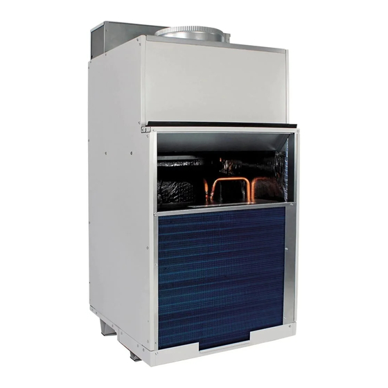
Single Package Vertical Air Conditioning System
AVH 9,000-24,000 Btu/hr Installation Instructions
ATTENTION INSTALLING PERSONNEL
As a professional installer you have an obligation to know
the product better than the customer. This includes all
safety precautions and related items.
Prior to actual installation, thoroughly familiarize yourself
with this Instruction Manual. Pay special attention to all
safety warnings.
Often during installation or repair it is possible to place
yourself in a position which is more hazardous than when
the unit is in operation.
IO-914
to Goodman Company, L.P., Houston, TX, USA. All rights reserved.
07/2020
5151 San Felipe, Suite 500 • Houston, TX 77056 • www.amana-ptac.com
& Owner's Manual
is a registered trademark of Maytag Corporation or its related companies and is used under license
© 2014 - 2015, 2017 - 2020 Goodman Company, L.P.
VTAC
Only personnel that have been trained to install, adjust, service
or repair(hereinafter, "service") the equipment specified in this
manual should service the equipment. The manufacturer will not
be responsible for any injury or property damage arising from
improper service or servide procedures. If you service this unit,
you assume responsibility for any injury or property damage
which may result. In addition, in jurisdictions that require one or
more licenses to service the equipment specified in this manual,
only licensed personnel should servise the equipment.
Improper installation, adjustment, servicing or repair of the
equipment specified in this manual, or attempting to install,
adjust, service or repair the equipment specified in this manual
without proper training may result in product damage, property
damage, personal injury or death.
FOR CALIFORNIA CONSUMERS
Cancer and Reproductive Harm -
WARNING
PROP 65 WARNING
WARNING
www.P65Warnings.ca.gov
0140M00513-A
1
Advertisement
Table of Contents

Related Manuals for Amana AVH24 Series


Summary of Contents for Amana AVH24 Series
- Page 1 Maytag Corporation or its related companies and is used under license IO-914 to Goodman Company, L.P., Houston, TX, USA. All rights reserved. 07/2020 5151 San Felipe, Suite 500 • Houston, TX 77056 • www.amana-ptac.com © 2014 - 2015, 2017 - 2020 Goodman Company, L.P.
-
Page 2: Table Of Contents
Contents Remember, it is your responsibility to install the product safely and to know it well enough to be able to instruct a customer in its safe use. Electrical Data ..............2 Supply Air Flow Data............3 Safety is a matter of common sense...a matter of thinking Control.................3 before acting. -
Page 3: Electrical Data
Electrical Data Electrical Rating Table Electrical Requirements NOTE: Use copper conductors ONLY. Wire sizes are per NEC. Wire Size Use ONLY wire size recommended for single outlet branch circuit. Recommended Branch Circuit Sizes* Fuse/Circuit Use ONLY type and size fuse or HACR Breaker circuit breaker indicated on unit’s rating AWG Wiring Size**... -
Page 4: Supply Air Flow Data
For thermostats with two-speed capability, connect the guidelines for proper spacing from the VTAC exterior LOW speed output to the GL terminal and the HIGH speed louvered grill. Amana recommends that ALL obstructions output to the GH terminal. are a minimum of 72” from the exhaust. -
Page 5: Installation Overview And Dimensional Data
BUILDING 24" VTAC VTAC VTAC SHRUB POLE OUTDOOR CONDENSING UNIT FENCE MAJOR OBSTRUCTION S 3/4” NOTE: The example pictured above is for reference only and does not represent all possilbe installations. Installation Overview and Dimensional Data Exterior Wall Adapter Cut-Out Dimensions (W x H): 24 5/8”... - Page 6 CLOSET INSTALLATIONS 23 1/8" 26 1/8" Min. 3" Required 23 1/8" Access Door Cutout = 27" 29 1/8" ( Min. Required Inside Closet Dimension ) 3 23 1/8" Access Door Cutout = 27" ...
- Page 7 Applicable Models AVH09xxxxxxxx AVH12xxxxxxxx Small Chassis Unit (Unit height 32”) Outside Wall Filter (14” x 20”) 11” 7" Architectural Grille 10" Part A AVAGK01xx Outside Exterior/ Wall Adapter Outside Wall 6" Part B Inside 2" Wall Adapter AVEWA05-08A = 5 1/2" - 8" D x 24 1/8" W x 30 3/8" H Unit AVEWA08-14A = 8"...
- Page 8 Field Supplied Parts: Sealant, attachment screws, and flashing are field supplied. Silicone sealant is recommended. AVEWA05-08A adjust for walls up to 4”- 8” thick. AVEWA08-14A adjust for walls up to 8” - 14” thick All installations are similar. Return Air Access Door Wall Cut-Out Dimensions (W x H): 27”...
-
Page 9: Louver Installation
Step 3 - Inside Wall Adapter (cont.) NOTE: Do not place any screws, fasteners, or penetrating holes through the top or bottom of the Wall Adapter assembly. 1. Drill pilot holes on the interior of the inside Wall Adapter half (Part B) as show in Detail B. Pilot holes should be located approximately 4”... -
Page 10: Final Wall Adapter And Architectural Louver Installation
Final Wall Adapter and Architectural Louver Installation NOTE: Ensure that the weather strip is undamaged and provides a continuous seal around the inner perimeter of the Wall Adapter. Apply silicone grease or other non-petroleum-based lubricants to the weather strip to enhance the sealing capability of the weather strip and ease installation of the air conditioner chassis. -
Page 11: Primary Drain Connection And Location
Primary Drain Connection and Location For AVH09 & AVH12 Units only NOTE: Failure to follow the following procedures may result in serious property damage. A field supplied secondary condensate pan or P-trap may be required. Check with local codes. In case of drainage system blockage, the unit base will allow excess water to flow out of the unit through the wall adapter and the architectural louver. - Page 12 Install Drain Pan DRAIN PAN INSTALLATION Attach the drain pan to the closet floor with the appropriate NOTE: This drain pan must be installed with all and field supplied hardware. "H" series units (Produced after AVH18-AVH24 September 2019). Important: To prevent water leaks use only the factory supplied mounting holes.
- Page 13 Important: Never run the condensate line as shown in Install Drain Line Option 4 below, as the drain line will come into contact with Condensate line routing options are shown below. Choose the factory-installed isolators beneath the unit. the one that best suits your installation. Option 1 Option 2 Run condensate line...
- Page 14 WIRING WARNING WARNING THIS AIR CONDITIONER IS NOT MEANT TO PROVIDE UNATTENDED COOLING OR LIFE SUPPORT FOR PERSONS OR ANIMALS WHO ARE UNABLE TO REACT TO THE FAILURE OF THIS PRODUCT. HIGH VOLTAGE THE FAILURE OF AN UNATTENDED AIR CONDITIONER MAY DISCONNECT ALL POWER BEFORE SERVICING RESULT IN EXTREME HEAT IN THE CONDITIONED SPACE OR INSTALLING THIS UNIT.
-
Page 15: Indoor Return Air Grille And Ductwork Installation
Indoor Return Air Grille and Ductwork NOTE: All VTAC chassis are shipped with a filter installed (20" x 14" for AVH09, AVH12, & AVH18. 20" x Installation 18" for AVH24). If a different filter holder or location is to be used, the filter on the chassis MUST be removed. AVLWP01A-R &... -
Page 16: Remote Thermostat And Low Voltage Control Connection
Auxiliary Fan Control The VTAC also has the ability to control a 24VAC relay to activate an auxiliary or transfer fan. The outputs are F1 and F2 on the control board. To connect the relay, simply wire one side of the relay to F1 and the other side to F2. -
Page 17: Final Installation Checklist
Final Installation Checklist Chassis Operation Fresh Air Door WARNING The fresh air door is an “intake” system. It is opened via a slide mechanism on the front of the chassis located just above the indoor coil. Move the slide left to open and right HIGH VOLTAGE DISCONNECT ALL POWER BEFORE SERVICING to close the door. -
Page 18: Routine Maintenance
Inspect and Clean Indoor-air Coil Eventually, minor amounts of lint and dirt may pass WARNING through the filter and collect on the indoor-air. These minor accumulations can be carefully vacuumed away with a HIGH VOLTAGE brush attachment on a vacuum claner. Care must be taken DISCONNECT ALL POWER BEFORE SERVICING to avoid bending the aluminum finns on the coil. -
Page 19: Error Codes And Alarm Status
ERROR CODES AND ALARM STATUS Unit Control Panel The display shown below has four (4) digits. The left two digits indicate the error code (1 to 24), The On/Off icons above these two digits indicate the currents state of the error code. The right two digits show the history count (up to 99) of the associated error code. -
Page 20: Obtaining Service
Maytag Corporation or its related companies and is used under license to Goodman Company, L.P., Houston, TX, USA. All rights reserved. 5151 San Felipe, Suite 500 • Houston, TX 77056 • www.amana-ptac.com © 2014 - 2015, 2017 - 2020 Goodman Company, L.P.