Aprilaire 8120 Series Installation And Operation Manual
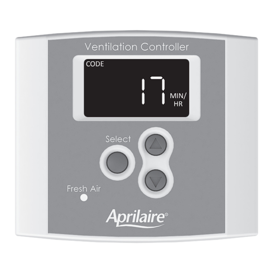
Digital ventilation controller
Hide thumbs
Also See for 8120 Series:
- Safety & installation instructions (13 pages) ,
- Owner's manual (2 pages) ,
- Installation instructions (2 pages)

Related Manuals for Aprilaire 8120 Series


Summary of Contents for Aprilaire 8120 Series
- Page 1 Model 8120X Digital Ventilation Controller Installation and Operation Manual CODE MIN/ READ AND SAVE THESE INSTRUCTIONS 61001433 B2207176E 12.20 English 1...
-
Page 2: Table Of Contents
TABLE OF CONTENTS WARNINGS AND CAUTIONS WARNINGS AND CAUTIONS . . . . . . . . . . . . . . . . . . . . . . . . . . . . . . . . . . . . . . . . . . . . . . . . . . . . . . . . . . . . . . . 3 WARNING PACKAGE CONTENTS . -
Page 3: Package Contents
PACKAGE CONTENTS MOUNTING THE CONTROLLER AND OUTDOOR TEMPERATURE SENSOR MOUNTING THE CONTROLLER TO THE RETURN DUCTWORK CONTROL #8 x 5/8" HEX HEAD SHEET METAL SCREW (2) NOTE: Mount the controller to the return ductwork at a location where the temperature and humidity #8 x 1/2"... -
Page 4: Mounting The Controller In A Closet Return Plenum
Duct Board Installation MOUNTING THE CONTROLLER IN A CLOSET RETURN PLENUM 1. Take out the duct board mounting bracket, remove the wall plate from the control and put the rest of the control in a safe location until after wiring is completed . NOTE: Do not mount directly in the path of the outdoor air . -
Page 5: Mounting The Outdoor Temperature Sensor
MOUNTING THE OUTDOOR TEMPERATURE SENSOR WIRING 1. Drill a 3/8" diameter hole in the duct of the fresh air inlet hood . Disconnect power to the HVAC system to prevent electrical shorts while wiring . 2. Install the outdoor temperature sensor into the duct and use metal foil tap to secure it in place 1. -
Page 6: Wiring To Heat Pump
FIGURE 2 – WIRING TO HEAT PUMP FIGURE 4 – WIRING TO MODEL 8142NC FRESH AIR VENTILATOR MODEL 8120X DIGITAL VENTILATION CONTROLLER* HEAT PUMP THERMOSTAT OR ZONE PANEL MODEL 8120X DIGITAL VENTILATION CONTROL Y W1 WIRE NUT (FIELD SUPPLIED) VENT R &... -
Page 7: Wiring To Model 6506 Damper
OPERATION FIGURE 6 – WIRING TO MODEL 6506 DAMPER The display will appear faint normally; the first press of any button will turn on the display at full power . Shows the ventilation time setting (minutes/hr), VENT mode of operation (Code or Comfort) and whether the HVAC fan has been turned on when ventilating . -
Page 8: Set Up Menu
SET UP MENU Menu Item Values Description HP if wiring to a heat pump . HP or HC NOTICE HC if wiring to furnace and AC . Before setting up the control for use, the amount of ventilation air being delivered (CFM) by CODE # BEDROOMS HIGH... -
Page 9: Test Mode
TEST MODE Menu Item Values Description Only available when bLnd is selected . When the outdoor OFF, 5°F less than COMFORT HOUSE (FT temperature is below the setting, the HVAC fan will be °F After wiring and set up have been completed, Test Mode can be used to verify that all Vent . -
Page 10: Rater/Inspector Verification
RATER/INSPECTOR VERIFICATION SEQUENCE OF OPERATION – “CODE” SETTING The control will turn on ventilation with a heating, cooling or fan call for the set number of minutes To verify the ventilation time setting, press the Select button to scroll through the calculated during a one-hour cycle period . -
Page 11: Limited Warranty
WARRANTY REGISTRATION Visit us online at www.aprilaire.com to register your Aprilaire product . If you do not have online access, please mail a postcard with your name, address, phone number, email address, product purchased, model number, date of purchase, and dealer name and address to: Research Products Corporation, P . - Page 12 Controlador digital del sistema de ventilación, modelo 8120X Manual de instalación y funcionamiento CODE MIN/ LEA Y CONSERVE ESTAS INSTRUCCIONES 61001433 B2207176E 12.20 Español 1...
- Page 13 ÍNDICE ADVERTENCIAS Y PRECAUCIONES ADVERTENCIAS Y PRECAUCIONES . . . . . . . . . . . . . . . . . . . . . . . . . . . . . . . . . . . . . . . . . . . . . . . . . . . . . . . . 3 ADVERTENCIA CONTENIDO DEL PAQUETE .
-
Page 14: Contenido Del Paquete
CONTENIDO DEL PAQUETE MONTAJE DEL CONTROLADOR Y EL SENSOR DE TEMPERATURA EXTERIOR MONTAJE DEL CONTROLADOR AL CONDUCTO DE RETORNO TORNILLO N.º 8 CON CABEZA SISTEMA DE CONTROL HEXAGONAL DE 5/8" PARA LÁMINAS METÁLICAS (2) NOTA: Monte el controlador al conducto de retorno en una ubicación donde la temperatura y la humedad TORNILLO N.º... -
Page 15: Montaje Del Controlador En Una Cámara De Retorno De Armario
Instalación del tablero del conducto MONTAJE DEL CONTROLADOR EN UNA CÁMARA DE RETORNO DE ARMARIO 1. Retire el soporte de montaje del tablero del conducto, retire la placa de pared del control y coloque el resto en un lugar seguro hasta que se complete el cableado . NOTA: No monte directamente en el conducto de aire exterior . -
Page 16: Montaje Del Sensor De Temperatura Exterior
MONTAJE DEL SENSOR DE TEMPERATURA EXTERIOR CABLEADO 1. Realice un orificio de 3/8" de diámetro en el conducto de la campana de admisión de aire fresco . Desconecte la energía del sistema de HVAC para evitar cortocircuitos cuando realice el cableado . 2. -
Page 17: Cableado A La Bomba De Calor
FIGURA 2: CABLEADO A LA BOMBA DE CALOR FIGURA 4: CABLEADO AL VENTILADOR DE AIRE FRESCO MODELO 8142NC TERMOSTATO CON BOMBA CONTROLADOR DIGITAL DEL SISTEMA SISTEMA DE CONTROL DIGITAL DEL SISTEMA DE CALOR O PANEL DE ZONAS DE VENTILACIÓN MODELO 8120X* DE VENTILACIÓN MODELO 8120X EMPALME Y W1... -
Page 18: Cableado Al Regulador Modelo 6506
FUNCIONAMIENTO FIGURA 6: CABLEADO AL REGULADOR MODELO 6506 Por lo general, la pantalla aparecerá con luz tenue; el primer botón que se presione encenderá la pantalla al máximo . Muestra la configuración de tiempo del sistema de ventilación (minutos/hora), el modo de funcionamiento (Código o Comodidad) y si el ventilador del sistema VENT de HVAC se encendió... -
Page 19: Menú De Configuración
MENÚ DE CONFIGURACIÓN Elemento del menú Descripción Valores HP si realiza la conexión a una bomba de calor . HP or HC AVISO HC si realiza la conexión a un sistema de calefacción o aire acondicionado . Antes de configurar el sistema de control, se debe medir la cantidad de aire de ventilación que se CODE # BEDROOMS HIGH... -
Page 20: Modo De Prueba
MODO DE PRUEBA Elemento del menú Descripción Valores Esta opción solo está disponible cuando se selecciona la opción CODE # BEDROOMS HIGH APAGADO, de 60 °F bLnd . Cuando la temperatura exterior es superior al valor Una vez que finalice el cableado y la configuración, se puede utilizar la función Test Mode (Modo de prueba) a 5 °F menos que °F configurado, el ventilador del HVAC se encenderá... -
Page 21: Verificación Del Evaluador/Inspector
VERIFICACIÓN DEL EVALUADOR/INSPECTOR SECUENCIA DE FUNCIONAMIENTO: CONFIGURACIÓN "CODE" El sistema de control encenderá la ventilación de acuerdo con una demanda de calefacción, enfriamiento o Para verificar la configuración del tiempo de ventilación, presione el botón Select (Seleccionar) para ventilación según la cantidad de minutos establecidos para un ciclo de una hora . Si la temperatura exterior es desplazarse por las opciones de Required Continuous CFM (CFM constantes necesarios) y Measured CFM superior al límite de temperatura alta del sistema de ventilación, la ventilación no se producirá... -
Page 22: Garantía Limitada
REGISTRO DE GARANTÍA Visite nuestro sitio web en www.aprilaire.com para registrar su producto Aprilaire . Si no tiene acceso en línea, envíe una carta con su nombre, dirección, número de teléfono, producto comprado, número de modelo, fecha de compra y nombre del distribuidor a la siguiente dirección: Research Products Corporation, P .