Table of Contents
Advertisement
Available languages
Available languages
Quick Links
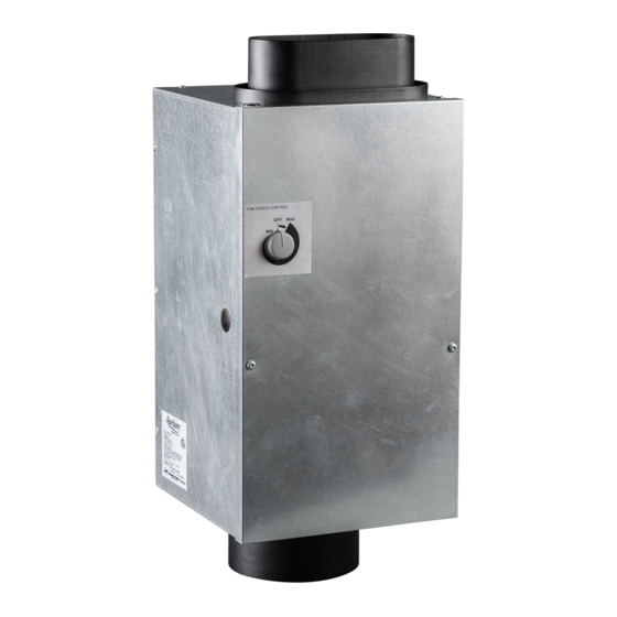
MOUNTING BRACKETS
6" DIAMETER
INLET COLLAR
SAFETY INSTRUCTIONS
1. 120 Volts may cause serious injury from electric shock. Disconnect electrical power before starting installation or servicing. Leave power
disconnected until installation/service is completed.
2. Sharp edges may cause serious injury from cuts. Use care when cutting plenum openings and handling duct work.
1. Read all instructions before beginning installation.
2. Improper installation may cause property damage or injury. Installation, service, and maintenance must be performed by a qualified service
technician.
10012276 B2207269A 4.18
Model 8144NC Fresh Air Ventilator
Installation and Operating Instructions
WIRE ENTRY LOCATION
ACCESS SCREWS
WARNING
CAUTION
READ AND SAVE THESE INSTRUCTIONS
MOTOR SPEED CONTROL
INTEGRAL PRESSURE
PORTS (PORT ON INLET
SIDE NOT SHOWN)
OVAL OUTLET COLLAR
FOR 6" DIAMETER DUCT
English 1
Advertisement
Table of Contents

Related Manuals for Aprilaire 8144NC


Summary of Contents for Aprilaire 8144NC
-
Page 1: Safety Instructions
Model 8144NC Fresh Air Ventilator Installation and Operating Instructions MOUNTING BRACKETS WIRE ENTRY LOCATION INTEGRAL PRESSURE PORTS (PORT ON INLET SIDE NOT SHOWN) OVAL OUTLET COLLAR FOR 6" DIAMETER DUCT 6" DIAMETER ACCESS SCREWS MOTOR SPEED CONTROL INLET COLLAR SAFETY INSTRUCTIONS WARNING 1. -
Page 2: Table Of Contents
INTRODUCTION AND COMPLIANCE STATEMENT The Model 8144NC Fresh Air Ventilator is designed to economically bring in precisely the right amount of fresh air into today’s efficiently designed homes and apartments. Duct the inlet of the ventilator to an outdoor air intake and the outlet to the return side of the HVAC system or into a mechanical closet, then set the desired flow. -
Page 3: Specifications
SPECIFICATIONS Airflow: 20-160 CFM Filter: MERV 6 washable FIGURE 1 – DIMENSIONS (INCHES) 10 3/4" 10 1/4" 13 1/16" 15 3/4" 10 1/4" 3 1/8" 18 1/8" 2 7/16" 90-2312 MOUNT THE VENTILATOR CAUTION FIGURE 2 – LOCATION CLEARANCES 1. Mount the blower with the lowest, exposed moving parts at least 8 feet (2.4 m) above floor or grade level. -
Page 4: Wiring & Electrical Specifications
Maximum Operating Current: 0.60 A The Model 8144NC Fresh Air Ventilator must be hard wired. An electrical disconnect switch can be installed as needed to comply with appropriate codes or ordinances. The ON/OFF switch on the ventilator interrupts the 115VAC service to the blower of the ventilator, but does not disconnect the power supply input to the unit. - Page 5 4. Insert the wires of the power cable into the wire entry hole on the side of the housing. By default the wire entry hole is nearest the FIGURE 5 – POWER WIRING power wires on the PCB. If it is desired to have the power wires enter from the other side, simply remove the plug installed in the wire entry hole on the other side and place it in the default location.
-
Page 6: Mount Intake Hood
MOUNT INTAKE HOOD Install a weather tight hood with a bird screen. Cut a hole in the exterior wall that is large enough to fit 6" insulated flexible duct through with minimal compression of the insulation. Pull the duct through the hole and attach the flex duct to the collar of the hood. Use metal foil tape or a plastic zip-tie to secure the duct to the collar. Pull the insulation and vapor barrier over the duct and tape it to the collar. -
Page 7: Install Ductwork
Freezing temperatures can cause pipes to rupture. Do not discharge outdoor air directly at a pipe or water heater, or any FURNACE /AIR MODEL 8144NC VENTILATOR other item at which unheated HANDLER MOUNTED TO WALL outdoor air should not be directed. -
Page 8: Wiring To External Controls
HVAC system. JUMPER CON1 3. Remove the motor speed adjustment knob, the cover and 8144NC CIRCUIT BOARD AS SHIPPED cover insulation, and the electrical compartment cover (see Figure 4) to access the ventilator circuit board. FIGURE 9 – WIRING TO 8910/8910W/8920W IAQ CONTROL 4. -
Page 9: Test And Setting
TEST AND SETTING 1. Restore power and turn on any disconnect switch to the ventilator FIGURE 12 2. Rotate the motor speed adjustment just past the on/off click to turn on the ventilator at maximum speed. If an external control is wired to the ventilator, turn the control on so the ventilator can run continuously. -
Page 10: Filter Cleaning
3. Use water to rinse the filter and then shake out the excess moisture from the filter. 4. Replace the filter in the ventilator and reinstall the cover insulation FILTER and the cover. 90-2316 INTERNAL SCHEMATIC FIGURE 15 – MODEL 8144NC INTERNAL ELECTRICAL SCHEMATIC BLOWER RUN CAPACITOR DAMPER MOTOR MOTOR SPEED CONTROLLER... -
Page 11: Limited Warranty
WARRANTY REGISTRATION Visit us online at www.aprilaire.com to register your Aprilaire product. If you do not have online access, please mail a postcard with your name, address, phone number, email address, product purchased, model number, date of purchase, and dealer name and address to: Research Products Corporation, P.O. Box 1467, Madison, WI 53701. - Page 12 AprilairePartners.com P.O. Box 1467 Madison, WI 53701-1467 800.334.6011 F: 608.257.4357 Printed in USA ©2018 Aprilaire – Division of Research Products Corporation 12 English...
- Page 13 Ventilador de aire fresco modelo 8144NC Instrucciones de instalación y funcionamiento SOPORTES DE MONTAJE UBICACIÓN DE ENTRADA DE LOS CABLES PUERTOS DE PRESIÓN INTEGRAL (NO SE MUESTRA EL PUERTO DEL LADO DE LA ENTRADA) ANILLO DE SALIDA OVALADO PARA CONDUCTO DE 6 IN DE DIÁMETRO...
- Page 14 INTRODUCCIÓN Y DECLARACIÓN DE CUMPLIMIENTO El ventilador de aire fresco modelo 8144NC está diseñado para incorporar de forma económica la cantidad precisa de aire fresco a las viviendas actuales diseñadas eficientemente. Conecte la entrada del ventilador a una entrada de aire exterior y la salida al lateral de retorno del sistema de HVAC o dentro de un armario mecánico y, luego, configure el flujo deseado.
- Page 15 ESPECIFICACIONES Flujo de aire: 20-160 CFM Filtro: MERV 6, lavable FIGURA 1: DIMENSIONES (PULGADAS) 10 3/4" 10 1/4" 13 1/16" 15 3/4" 10 1/4" 3 1/8" 18 1/8" 2 7/16" 90-2312 INSTALACIÓN DEL VENTILADOR PRECAUCIÓN FIGURA 2: SEPARACIONES 1. Con la menor cantidad de piezas móviles expuestas, instale el soplador al menos a 8 pies (2.4 m) del piso o del nivel del suelo.
- Page 16 Corriente máxima de funcionamiento: 0.60 A El ventilador de aire fresco modelo 8144NC se debe conectar firmemente. Se puede instalar un interruptor de desconexión eléctrica según sea necesario para cumplir con los códigos y las ordenanzas adecuados. El interruptor ON/OFF (Encendido/apagado) que se encuentra en el ventilador interrumpe el servicio de 115 VCA para el soplador del ventilador, pero no desconecta la entrada de alimentación a la unidad.
- Page 17 4. Introduzca los cables de alimentación en el orificio de entrada de los cables que se encuentra al costado de la carcasa. Por defecto, el orificio FIGURA 5: CABLEADO de entrada de los cables se encuentra más cerca de los cables de alimentación en el Tablero de circuito impreso (Printed Circuit Board, PCB).
- Page 18 INSTALACIÓN DEL EXTRACTOR DE ADMISIÓN Instale un extractor hermético con una malla contra pájaros. Haga un agujero en la pared exterior que sea lo suficientemente grande como para que ingrese un conducto flexible aislado de 6 in con una compresión mínima del aislamiento.
- Page 19 No descargue aire exterior directamente a una tubería o a un SISTEMA DE VENTILADOR MODELO 8144NC calentador de agua, o a cualquier CALEFACCIÓN/ INSTALADO EN LA PARED otro elemento al que no se deba CLIMATIZADOR dirigir el aire exterior sin calentar.
- Page 20 PREVIAMENTE aislante de la tapa y la tapa del compartimiento eléctrico (consulte lar TABLERO DE CIRCUITO DEL MODELO 8144NC, TAL COMO SE ENVIÓ figura 4) para acceder al tablero de circuito del ventilador. 4. Corte el cable del puente de conexión...
- Page 21 PRUEBAS Y CONFIGURACIÓN 1. Conecte y encienda cualquier interruptor de desconexión al ventilador. 2. Gire el ajuste de velocidad del motor justo después de escuchar el sonido de FIGURA 12 clic de encendido/apagado para encender el ventilador a máxima velocidad. Si un sistema de control externo está...
- Page 22 3. Enjuague el filtro y luego sacuda el exceso de humedad del filtro. 4. Reemplace el filtro en el ventilador y vuelva a colocar el aislante de la tapa y la tapa. FILTRO 90-2316 ESQUEMA INTERNO FIGURA 15: ESQUEMA ELÉCTRICO INTERNO DEL MODELO 8144NC SOPLADOR CONDENSADOR DE MARRÓN AZUL FUNCIONAMIENTO...
- Page 23 GARANTÍA LIMITADA El ventilador de aire fresco de Research Products Corporation de Aprilaire® cuenta con una garantía de cinco (5) años a partir de la fecha de instalación que cubre defectos materiales o de mano de obra. La obligación exclusiva de Research Products Corporation bajo esta garantía es la de suministrar, sin cargo, un repuesto para cualquier pieza que esté dañada dentro del período de los cinco (5) años mencionado y usted o su proveedor original puede devolverlo hasta treinta (30) días después del período de 5 (cinco) años a Research Products Corporation, Madison, Wisconsin 53701, junto con el número de modelo y la fecha de...
- Page 24 AprilairePartners.com P.O. Box 1467 Madison, Wisconsin 53701-1467 800.334.6011 F: 608.257.4357 Impreso en EE. UU. ©2018 Aprilaire. Una división de Research Products Corporation 12 Español...