
Related Manuals for Danfoss BOCK FK40


Summary of Contents for Danfoss BOCK FK40
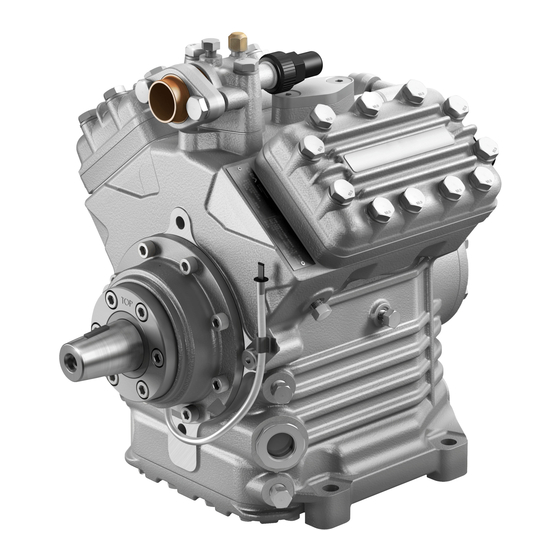
- Page 1 FK 4 BOCK ® Operating guide FKX40/470 K FKX40/560 K FKX40/655 K Translation of the original instructions AQ450736920607en-000201...
- Page 2 Such persons must read the safety advice and have understood it. Bock assumes no liability for any damage arising from non-compliance. © Danfoss | Climate Solutions | 2023.07 2 | AQ450736920607en-000201...
-
Page 3: Table Of Contents
6.3 Shaft seal, emptying the oil reservoir 6.4 Recommended spare parts / accessories 6.5 Integrated decompression valve 6.6 Lubricants / oils 6.7 Decommissioning Accessories 7.1 Capacity regulator Technical data Dimensions and connections 10 Declaration of incorporation © Danfoss | Climate Solutions | 2023.07 AQ450736920607en-000201 | 3... -
Page 4: Safety
• If there is a sharp reduction in refrigerating capacity, switch the compressor off immediately. • Secure the compressor against being switched on again. • In such cases do not continue to operate the compressor under any circumstances. © Danfoss | Climate Solutions | 2023.07 4 | AQ450736920607en-000201... -
Page 5: Intended Use
Commissioning is permissible only if the compressor has been installed in accordance with these as- sembly instructions and the entire system into which it is integrated has been inspected and approved in accordance with legal regulations. © Danfoss | Climate Solutions | 2023.07 AQ450736920607en-000201 | 5... -
Page 6: Product Description
Shaft end Oil sight glass Fig. 1 Suction shut-off valve Cylinder cover Valve plate Oil pump Oil sight glass Fig. 2 Dimension and connection values can be found in Chapter 9 © Danfoss | Climate Solutions | 2023.07 6 | AQ450736920607en-000201... -
Page 7: Type Key
HP: Max. permissible operating pressure (g) High pressure side 2.3 Type key (example) 655 K Design ¹ Swept volume Size Ester oil charge ² Series ¹ K - specially for air-conditioning ² X - Ester oil charge (HFC refrigerant, e.g. R134a, R407C) © Danfoss | Climate Solutions | 2023.07 AQ450736920607en-000201 | 7... -
Page 8: Areas Of Application
Prevent the ingress of air at all costs! Maximum admissible LP = Low pressure operating pressure (g) HP = High pressure (LP/HP) : 19/28 bar © Danfoss | Climate Solutions | 2023.07 8 | AQ450736920607en-000201... -
Page 9: Compressor Assembly
4.2 Maximum permissible inclination ATTENTION Poor lubrication can damage the compressor. Respect the stated values. max. 30°, max. 2 minutes max. 15°, continuous operation Fig. 6 © Danfoss | Climate Solutions | 2023.07 AQ450736920607en-000201 | 9... -
Page 10: V-Belt Drive
The following description applies for an electromagnetic clutch secured to a shaft. To absorb the magnetic field of the electromagnetic clutch, the front bearing flange has a snug fit Ø 148 h8 (see Fig. 8). To connect the magnetic field, loosen the 4 cheese head screws M8 on the bearing flange (see Fig. 8). Slide the magnetic field to a snug fit and re-attach using the four cheese head screws M8 (Fig. 9). Screw torque = 37 Nm. Further assembly of the electromagnetic clutch according to the clutch manufacturer. Bearing flange, front Magnetic field Fig. 8 Fig. 9 148 h8 © Danfoss | Climate Solutions | 2023.07 10 | AQ450736920607en-000201... -
Page 11: Pipe Connections
Before opening or closing the shut-off valve, release the valve spindle seal by approx. ¼ of a turn counter-clockwise. After activating the shut-off valve, re-tighten the adjustable valve spindle seal clockwise. Release Tighten Tighten Valve spindle seal Valve spindle seal Fig. 11 Fig. 12 © Danfoss | Climate Solutions | 2023.07 AQ450736920607en-000201 | 11... -
Page 12: Operating Mode Of The Lockable Service Connections
Connection 3 is provided for safety devices and is not lockable. After activating the spindle, generally fit the spindle protection cap again and tighten with 14-16 Nm. This serves as a second sealing feature during operation. 4.10 Suction pipe filter For systems with long pipes and higher degree of contamination, a filter on the suction-side is recommended. The filter has to be be renewed depending on the degree of contamination (reduced pressure loss). © Danfoss | Climate Solutions | 2023.07 12 | AQ450736920607en-000201... -
Page 13: Commissioning
Evacuate the suction and discharge pressure sides using the vacuum pump. At the end of the evacuation process, the vacuum should be < 1.5 mbar when the pump is switched off. Repeat the process as often as is required. © Danfoss | Climate Solutions | 2023.07 AQ450736920607en-000201 | 13... -
Page 14: Refrigerant Charge
0.05 ml per operating hour is therefore normal. This applies particularly during the run-in phase (200 - 300 h). T o trap and collect leaked oil, the FK40 is fitted with an inte- grated leak oil trapping device with oil reservoir (P.6, Fig. 1). © Danfoss | Climate Solutions | 2023.07 14 | AQ450736920607en-000201... -
Page 15: Avoiding Liquid Shocks
Switch off the compressor and secure it to prevent a restart. Relieve compressor of system pressure. Prevent air from infiltrating the system! After maintenance has been performed: Connect safety switch. Evacuate compressor. Release switch lock. © Danfoss | Climate Solutions | 2023.07 AQ450736920607en-000201 | 15... -
Page 16: Work To Be Carried Out
After Fig. 15 emptying, reseal the oil hose and clamp it into the bracket. Dispose of the used oil in accordance with national regulations. © Danfoss | Climate Solutions | 2023.07 16 | AQ450736920607en-000201... -
Page 17: Recommended Spare Parts/Accessories
Bock! Bock assumes no liability for any damage arising from alternative oil types. Refrigerant Bock standard oil grade BOCK lub E55 (e.g. R134a, R407, R 404A) HCFC (e.g. R22) BOCK lub A46 © Danfoss | Climate Solutions | 2023.07 AQ450736920607en-000201 | 17... -
Page 18: Decommissioning
... K Designation Art.-Nr. Capacity regulator 12 V 097B40510* Capacity regulator 24 V 097B40511* For a description, see technical information "Capacity regulation" (Item No. 097B09900*) If the capacity regulator is factory-fitted, it is integrated into an extra, dedicated cylinder cover. For retrofits, it is supplied with the cylinder cover. The regulator closes one cylinder bank (capacity regula- tion approx. 50%). * Please note that the legacy BOCK code numbers are without 097B © Danfoss | Climate Solutions | 2023.07 18 | AQ450736920607en-000201... -
Page 19: Technical Data
8| Technical data Oil pump Lubri cation No. of cylinders © Danfoss | Climate Solutions | 2023.07 AQ450736920607en-000201 | 19... -
Page 20: Dimensions And Connections
Part-No. Baumustergeprüft / Type examination: 000B 40711 .0 Nein / No Gewicht / Weight: (kg) © Danfoss | Climate Solutions | 2023.07 20 | AQ450736920607en-000201 Allgemeintoleranzen / General tolerances Benennung / Description: DIN ISO 2768-mK-E ußtoleranzen / General casting tolerances: Zeichnungs-Nr. - Page 21 4 " NPTF 2 x 1 1 / 8 "- 18 UNEF Sight glass Connection thermal protection thermostat 8 " NPTF Oil filter M22 x 1.5 Opt. connection suction line valve © Danfoss | Climate Solutions | 2023.07 AQ450736920607en-000201 | 21...
-
Page 22: Declaration Of Incorporation
Prasad Sannagowder #3A1, Bommasandra Industrial Area, Hebbagodi, Bock GmbH Hosur Road, Bangalore – 560099 Alexander Layh Benzstraße 7 72636 Frickenhausen, Germany Prasad Sannagowder, Managing Director Frickenhausen, 02nd of March 2021 © Danfoss | Climate Solutions | 2023.07 22 | AQ450736920607en-000201... - Page 23 © Danfoss | Climate Solutions | 2023.07 AQ450736920607en-000201 | 23...
- Page 24 © Danfoss | Climate Solutions | 2023.07 24 | AQ450736920607en-000201...