Advertisement
Quick Links
www.ti.com
EVM User's Guide: TAS2574 TAS2574EVM
TAS2574 Evaluation Module
Description
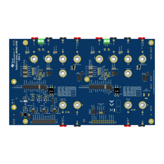
The TAS2574EVM has been designed to demonstrate
the performance of TAS2574 in a dual-mono
configuration. This tool utilizes the AC-MB
motherboard to provide an interface and supply
voltages to the EVM daughter card. Up to four devices
can share a common bus through I
interfaces; two EVMs can be mounted one on top of
each other, as shown in
Section
Get Started
1. Download
TAS2574 data
2. Order the EVM at
TAS2574 product
3. Request access and download PPC3 from
TAS2574 product
folder.
SLAU896 – JULY 2023
Submit Document Feedback
2
2
S/TDM + I
C
2.8.
sheet.
folder.
TAS2574 Dual-Mono Evaluation Module
Copyright © 2023 Texas Instruments Incorporated
4. Visit and ask questions at
Features
•
Mono or dual-mono speaker evaluation
•
Interface using PurePath Console 3 Windows
software
•
EVM interconnection for up to 4 audio channels
•
USB input
2
2
•
External I
C and I
S/TDM host controller
connection available
Applications
•
Mobile
Phone,
Tablets
•
Smart Speakers with Voice Assistance
•
Bluetooth and Wireless Speakers
Description
e2e
forum.
®
and
Wearables
TAS2574 Evaluation Module
1
Advertisement

Related Manuals for Texas Instruments TAS2574


Summary of Contents for Texas Instruments TAS2574
- Page 1 4. Visit and ask questions at forum. Description Features The TAS2574EVM has been designed to demonstrate the performance of TAS2574 in a dual-mono • Mono or dual-mono speaker evaluation configuration. This tool utilizes the AC-MB • Interface using PurePath Console 3 Windows ®...
-
Page 2: Kit Contents
2.4V to 5.5V. 1.3 Specification The TAS2574 is a digital input Class-D audio amplifier optimized for delivering best battery life for real use case of music playback and voice calls. The integrated boost operation is flexible so that TAS2574 can be implemented in 1S, 2S and 3S battery applications. -
Page 3: Device Information
Figure 1-3. Application Diagram for 3 S Battery System 1.4 Device Information TAS2574 is a mono, digital-input, Class-D audio amplifier optimized for efficiently driving high peak power into small loudspeaker applications. The Class-D amplifier is capable of delivering 6W of max average power into 8 Ω... - Page 4 The AC-MB is detected by the OS as an audio device with the name TI USB Audio UAC2.0. Figure 2-2 illustrates the AC-MB audio setting for the USB mode of operation. Figure 2-2. AC-MB USB Audio Setting TAS2574 Evaluation Module SLAU896 – JULY 2023 Submit Document Feedback Copyright © 2023 Texas Instruments Incorporated...
- Page 5 Figure 2-4. AC-MB Connection with External Audio Serial Interface SLAU896 – JULY 2023 TAS2574 Evaluation Module Submit Document Feedback Copyright © 2023 Texas Instruments Incorporated...
- Page 6 TAS2574EVM. Figure 2-6. Default Jumper Settings Table 4-1 shows the default positions for all the jumpers on TAS2574EVM. TAS2574 Evaluation Module SLAU896 – JULY 2023 Submit Document Feedback Copyright © 2023 Texas Instruments Incorporated...
- Page 7 IOVDD source selector for U1 and U2 J36-11-10 IOVDD_MB AVDD source selector for U1 and U2 Insert (2-3) 1.8V LDO source selector Insert C pull-up connect Insert C pull-up connect SLAU896 – JULY 2023 TAS2574 Evaluation Module Submit Document Feedback Copyright © 2023 Texas Instruments Incorporated...
- Page 8 IOVDD is the input/output power supply for TAS2574 device, which can be either 1.2V or 1.8V. AVDD is the analog power supply for TAS2574 device, which is 1.8V fixed. If using IOVDD_MB from AC-MB as 1.2V, then make sure to select AVDD source to be either external or +1.8V_LDO.
- Page 9 J45. 2.6 VBAT Power Supply for TAS2574 on EVM By default, the barrel jack connector J43 is used to power VBAT on both TAS2574 channels. Supply 2.4V-5.5V on this connector. Alternatively, independent connectors can be used for the external VBAT supply for both the channels –...
- Page 10 In addition to the jumper configurations, make sure each amplifier is set for a different I C address using S2 and S3 on each EVM. TAS2574 Evaluation Module SLAU896 – JULY 2023 Submit Document Feedback Copyright © 2023 Texas Instruments Incorporated...
-
Page 11: Speaker Outputs
TP-42 (SPK2_P) and TP-44 (SPK2_N) Channel-1 Output Channel-2 Output SPK1_P & SPK1_N SPK2_P & SPK2_N Figure 2-11. Speaker Output Connector for Channel-1 and Channel-2 SLAU896 – JULY 2023 TAS2574 Evaluation Module Submit Document Feedback Copyright © 2023 Texas Instruments Incorporated... - Page 12 Connect LO of DMM to pin-2 and LO_SNS of DMM to pin-1 of TP43 test point. Figure 2-12. Load DC Resistance Measurement in 4-Wire Mode using Digital Multimeter TAS2574 Evaluation Module SLAU896 – JULY 2023 Submit Document Feedback Copyright © 2023 Texas Instruments Incorporated...
- Page 13 Once the board is powered and connected to USB, and the PPC3 plug-in is running, the PC automatically recognizes the device (TAS2574). PPC3 detect as well as the number of channels, depending on how many of these are being powered and present on the I C bus.
- Page 14 Figure 3-3. Device Control Panel 3.2 PPC3 - 257x EVM Feature Description 3.2.1 Limiter and Brown-Out Protection TAS2574 features battery tracking brown-out and limiter features. Each of these features can be configured in detail as listed below: Brown-out protection: •...
- Page 15 • Attack, Hold, and Slope parameters set the dynamic gain controller timing settings. Figure 3-4. Limiter PPC3 Configuration Figure 3-5. Brown-Out Protection PPC3 Configuration SLAU896 – JULY 2023 TAS2574 Evaluation Module Submit Document Feedback Copyright © 2023 Texas Instruments Incorporated...
- Page 16 Feedback path High-Pass Filter cutoff frequencies can be adjusted manually using the slider or typing a new value in the text box. Figure 3-6. Playback and PCM PPC3 Configuration TAS2574 Evaluation Module SLAU896 – JULY 2023 Submit Document Feedback Copyright © 2023 Texas Instruments Incorporated...
- Page 17 8-bit, so for 16-bit data length 2 slots must be used, and for 32bit data length 4 slots are required. Figure 3-8. TDM Transmitter PCM PPC3 Configuration SLAU896 – JULY 2023 TAS2574 Evaluation Module Submit Document Feedback Copyright © 2023 Texas Instruments Incorporated...
- Page 18 3.2.4 Miscellaneous and IRQ Configuration The miscellaneous section can be used to change different portions of the digital interface pins of the TAS2574. The over temperature, over current and internal clock error can be configured to latch or retry after a wait time, which is also configurable as 1.5 seconds or 100 milliseconds.
- Page 19 3.2.5 Tone Generator and Ultrasonic Chirp Generator TAS2574 features internal tone generator that can be used independently from the digital audio playback. This sine wave generator can be used in the audible frequency band, or for ultrasonic applications as well. However, only one of these cases can be used at a time.
- Page 20 3.2.6 AVDD Bridge, Music Efficiency and Noise Gate TAS2574 includes several features to improve the amplifier efficiency and prolong the play time in battery powered applications. All these features can be configured individually, and even disable if not required for the...
- Page 21 Software 3.2.7 Boost and Channel Gain The channel gain section of the PPC3 GUI provides detailed settings for the integrated boost in TAS2574. Each of the controls are described in the following paragraphs. Amplifier level is the gain of the amplifier, up to 16dBV analog gain and beyond that some digital gain can be applied.
- Page 22 IOVDD2 AVDD2 DREG2 PGND VBAT2_SNS PGND PGND 1000pF 1000pF SPC02SYAN TAS2574 1000pF TP46 TP47 TP48 TP49 Figure 4-1. TAS2574EVM Schematic (Sheet 1 of 3) TAS2574 Evaluation Module SLAU896 – JULY 2023 Submit Document Feedback Copyright © 2023 Texas Instruments Incorporated...
- Page 23 33.0 SBCLK 33.0 SPC02SYAN SPC02SYAN FSYNC I2C_SDA I2C_SCL SH-J37 SH-J38 I2C_SDA I2C_SDA I2C_SDA2 I2C_SDA1 SPC02SYAN SPC02SYAN Figure 4-3. TAS2574EVM Schematic (Sheet 3 of 3) SLAU896 – JULY 2023 TAS2574 Evaluation Module Submit Document Feedback Copyright © 2023 Texas Instruments Incorporated...
-
Page 24: Pcb Layouts
Hardware Design Files www.ti.com 4.2 PCB Layouts Figure 4-4. TAS2574EVM Top Overlay Figure 4-5. TAS2574EVM Top Solder Mask TAS2574 Evaluation Module SLAU896 – JULY 2023 Submit Document Feedback Copyright © 2023 Texas Instruments Incorporated... - Page 25 Hardware Design Files Figure 4-6. TAS2574EVM Top Layer Figure 4-7. TAS2574EVM Layer 2 SLAU896 – JULY 2023 TAS2574 Evaluation Module Submit Document Feedback Copyright © 2023 Texas Instruments Incorporated...
- Page 26 Hardware Design Files www.ti.com Figure 4-8. TAS2574EVM Layer 3 Figure 4-9. TAS2574EVM Layer 4 TAS2574 Evaluation Module SLAU896 – JULY 2023 Submit Document Feedback Copyright © 2023 Texas Instruments Incorporated...
- Page 27 Hardware Design Files Figure 4-10. TAS2574EVM Layer 5 Figure 4-11. TAS2574EVM Bottom Layer SLAU896 – JULY 2023 TAS2574 Evaluation Module Submit Document Feedback Copyright © 2023 Texas Instruments Incorporated...
- Page 28 Hardware Design Files www.ti.com Figure 4-12. TAS2574EVM Bottom Solder Mask Figure 4-13. TAS2574EVM Bottom Overlay TAS2574 Evaluation Module SLAU896 – JULY 2023 Submit Document Feedback Copyright © 2023 Texas Instruments Incorporated...
-
Page 29: Bill Of Materials (Bom)
LTST-C170TBKT Lite-On H1, H2, H3, H4, B&F Fastener HNSS440 Supply RAF Electronic H5, H6 8 MM RD X 6 MM X M3 10x10mm M3561-SS Hardware SLAU896 – JULY 2023 TAS2574 Evaluation Module Submit Document Feedback Copyright © 2023 Texas Instruments Incorporated... - Page 30 Standard Banana Jack, 571-0100 571-0100 J67, J70, J73 insulated, 10 A, black Manufacturing Header, 100mil, 2x2, J29, J32 2x2 Header TSW-102-07-G-D Samtec Gold, TH TAS2574 Evaluation Module SLAU896 – JULY 2023 Submit Document Feedback Copyright © 2023 Texas Instruments Incorporated...
- Page 31 3.9x2.9mm SKRKAEE020 Alps A, 12 VDC, SMT Switch, Slide, 2 SPST, Omron Electronic S2, S3 Off-On, 0.025 A, 24 7x7.5mm A6SN-2104 Components VDC, SMT SLAU896 – JULY 2023 TAS2574 Evaluation Module Submit Document Feedback Copyright © 2023 Texas Instruments Incorporated...
- Page 32 Driver With Open-Drain SN74AUP2G07D Texas DCK0006A Outputs, DCK0006A Instruments (SOT-SC70-6) Single-Bit Dual-Supply Texas SN74AXC1T45D Texas U5, U6 Bus Transceiver, DBV0006A Instrument Instruments DBV0006A (SOT-23-6) TAS2574 Evaluation Module SLAU896 – JULY 2023 Submit Document Feedback Copyright © 2023 Texas Instruments Incorporated...
-
Page 33: Additional Information
R30, R34 5 Additional Information 5.1 Trademarks Windows ® is a registered trademark of Microsoft Corporation. All trademarks are the property of their respective owners. SLAU896 – JULY 2023 TAS2574 Evaluation Module Submit Document Feedback Copyright © 2023 Texas Instruments Incorporated... - Page 34 STANDARD TERMS FOR EVALUATION MODULES Delivery: TI delivers TI evaluation boards, kits, or modules, including any accompanying demonstration software, components, and/or documentation which may be provided together or separately (collectively, an “EVM” or “EVMs”) to the User (“User”) in accordance with the terms set forth herein.
- Page 35 www.ti.com Regulatory Notices: 3.1 United States 3.1.1 Notice applicable to EVMs not FCC-Approved: FCC NOTICE: This kit is designed to allow product developers to evaluate electronic components, circuitry, or software associated with the kit to determine whether to incorporate such items in a finished product and software developers to write software applications for use with the end product.
- Page 36 www.ti.com Concernant les EVMs avec antennes détachables Conformément à la réglementation d'Industrie Canada, le présent émetteur radio peut fonctionner avec une antenne d'un type et d'un gain maximal (ou inférieur) approuvé pour l'émetteur par Industrie Canada. Dans le but de réduire les risques de brouillage radioélectrique à...
- Page 37 www.ti.com EVM Use Restrictions and Warnings: 4.1 EVMS ARE NOT FOR USE IN FUNCTIONAL SAFETY AND/OR SAFETY CRITICAL EVALUATIONS, INCLUDING BUT NOT LIMITED TO EVALUATIONS OF LIFE SUPPORT APPLICATIONS. 4.2 User must read and apply the user guide and other available documentation provided by TI regarding the EVM prior to handling or using the EVM, including without limitation any warning or restriction notices.
- Page 38 Notwithstanding the foregoing, any judgment may be enforced in any United States or foreign court, and TI may seek injunctive relief in any United States or foreign court. Mailing Address: Texas Instruments, Post Office Box 655303, Dallas, Texas 75265 Copyright © 2023, Texas Instruments Incorporated...
- Page 39 TI products. TI’s provision of these resources does not expand or otherwise alter TI’s applicable warranties or warranty disclaimers for TI products. TI objects to and rejects any additional or different terms you may have proposed. IMPORTANT NOTICE Mailing Address: Texas Instruments, Post Office Box 655303, Dallas, Texas 75265 Copyright © 2023, Texas Instruments Incorporated...