
Related Manuals for Nortel CTR 2800

Summary of Contents for Nortel CTR 2800
- Page 1 411- 1333 -203 Reunion CTR 28 GHz Sub-Bands 28-01P1, 28-01P2 and 28-07P Outdoor Microwave Transceiver Installation Guide Release 1.2 March 1999...
- Page 3 Reunion CTR 2800 Outdoor Microwave Transceiver Installation Guide Document number: 411- 1333 - 203.01.02 Product release: Release 1.2 Document version: Preliminary Date: March 1999 Copyright Country of printing Confidentiality Legal statements Trademarks © 1999 Northern Telecom Northern Telecom Ltd., all rights reserved...
-
Page 5: Publication History
Publication history September 1998 • Draft release of the document • Subject to change without notice March 1999 • Preliminary release of the document • Subject to change without notice Reunion CTR 28 GHz Installation Guide... - Page 6 411- 1333 - 203.01.02 Preliminary March 1999...
-
Page 7: About This Guide
This guide provides the information required to install and operate the CTR 28 GHz outdoor microwave transceiver. The CTR 28 GHz is one of the Radio Frequency (RF) products that constitute a Nortel Reunion product line. The associated products include the following types of cell site equipment: •... -
Page 8: Organization
• Reunion Safety Standards provide a quick review of general safety guidelines. • Installing the CTR 2800 explains how to physically install the transceiver. • CTR 2800 Maintenance describes basic maintenance procedures to ensure that the transceiver is operating correctly. -
Page 9: Documentation Suite
Documentation Suite This Reunion Release has a suite of fifteen documents: Reunion System Overview, 411- 1343 - 010 Reunion Network Node Equipment Installation Guide, 411- 1313 - 200 Reunion NIU 6054 Network Interface Unit Installation Guide, Release 1.2, 411- 1323 - 201 Reunion NIU 6154 Network Interface Unit Installation Guide, Release 1.2, 411- 1323 - 202 Reunion NIU 5008 Network Interface Unit Installation Guide,... -
Page 10: Customer Support
In addition, Nortel Networks Broadband Wireless Access (BWA) provides 24-hour customer service and technical support to ensure your service operation is trouble-free. If you have questions or need technical support, contact Nortel Networks Broadband Wireless Access at the following telephone numbers: •... -
Page 11: Table Of Contents
Contents Publication history v About this guide vii Purpose vii Audience vii Organization viii Documentation Suite ix Customer Support x Contents xi CTR 28 GHz Release 1.2 Product Overview 1-1 How the CTR 28 GHz Works 1-2 CTR 28 GHz Specification 1-4 CTR 28 GHz Component Descriptions 1-6 Diplexer / Power Supply 1-6 Mixer 1-6... - Page 12 Grounding and Surge Protection Grounding/Lightning Protection 2-1 Scope 2-1 Grounding Methods/Indoor Equipment 2-1 Wire Gauge Guidelines 2-2 Outdoor Equipment: the need for surge (lightning) protection 2-3 Ground connections to outdoor equipment 2-7 Regulatory Considerations 2-10 List of terms 411- 1333 - 203.01.02 Preliminary March 1999...
-
Page 13: Ctr 28 Ghz Release 1.2
The CTR 28 GHz outdoor transceiver is a customer premise transceiver designed to operate in the Receiver (RX) 27.5485 to 27.7485 GHz and Transmitter (TX) 28.5565 to 28.7565 GHz frequency bands. It is a Nortel Reunion product which operates in conjunction with base station products. It is compatible with Reunion’s Release 1.2 equipment. -
Page 14: How The Ctr 28 Ghz Works
1-2 CTR 28 GHz Release 1.2 Figure 1-1 CTR 28 GHz Block Diagram Diplexer 18 VDC IF/PS Input Power Supply TX Filter P. Amp. TX Filter 12 VDC Antenna Mixer Duplexer Mixer RX Filter RX Filter LO Test Port IF Output VHF-AMP How the CTR 28 GHz Works This section provides an overview of the theory of operation for the CTR 28... - Page 15 CTR 28 GHz Release 1.2 1-3 1. The CTR transceiver’s input coaxial cable carries the IF signals and the 18 VDC power supply to the diplexer. The diplexer distributes the DC power to the power supply unit and interfaces with the mixer for the IF signals. 2.
-
Page 16: Ctr 28 Ghz Specification
1-4 CTR 28 GHz Release 1.2 CTR 28 GHz Specification Table 1: CTR 28 GHz Specifications IF Input RF Output Frequency Range 28-01P1 538-650 MHz 28.5565-28.6685 GHz 28-01P2 28.6405-28.7525 GHz 28-07P 28.2-28.35 GHz ≥ Output Level (P1dB) 21 dBm, -40° to +30°C ≥... - Page 17 CTR 28 GHz Release 1.2 1-5 Antenna Frequency 27.5-29.5 GHz Gain 35 dBi, minimum TX / RX wave polarity linear, single pole Beam Width (3dB) 2.6° Diameter 1’ (30.5 cm) Power Supply Input Voltage 18 VDC, 3A, max diplexed with TX cable Input Current <3 Amp Input Power...
-
Page 18: Ctr 28 Ghz Component Descriptions
1-6 CTR 28 GHz Release 1.2 CTR 28 GHz Component Descriptions Diplexer / Power Supply The diplexer separates the IF input signals and the DC power supply. The isolation between the IF path and the power supply path is more than 45 dB. A transient voltage protector on the board helps to protect the transceiver from possible lightning damage. -
Page 19: Low Noise Amplifier
CTR 28 GHz Release 1.2 1-7 Low Noise Amplifier The low noise amplifier (LNA) provides gain in the receive path and amplifies the received microwave signals to the mixer. The gain and noise figure of the LNA are chosen to maximize the overall dynamic range and noise performance of the CTR 28 GHz receiver section. -
Page 20: Pre-Installation
Failure to prevent unauthorized user access invalidates the equipment warranty. Unpacking Shipment Use the following steps to unpack and inspect the shipment of Nortel Broadband Wireless Access equipment: 1. Copy adequate Inventory Forms 2. -
Page 21: Reunion Safety Standards
CTR 28 GHz Release 1.2 1-9 Reunion Safety Standards Safety and safety considerations are important while using Nortel Broadband Wireless Access equipment. Safety Disclaimer The safety standards discussed in this guide cannot address all safety problems associated with their use or all applicable regulatory requirements. -
Page 22: Installing The Ctr 28 Ghz
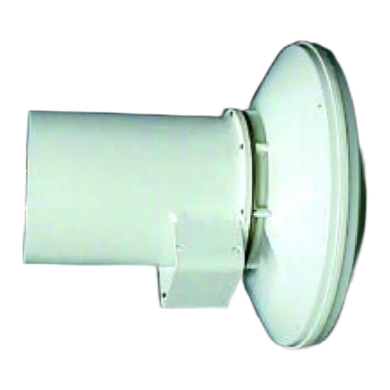
1-10 CTR 28 GHz Release 1.2 Installing the CTR 28 GHz Installation involves three separate operations: • mounting bracket assembly • installing the tower equipment • installing the indoor equipment For information about installing the antenna(s) and such aspects as line of sight, antenna mast spacing, coverage angle, etc., refer to the Network Engineering Package and the Design Document. -
Page 23: Installing The Tower Equipment
CTR 28 GHz Release 1.2 1-11 Installing the Tower Equipment Install the CTR 28 GHz microwave transceiver as follows: 1. Mount the CTR 28 GHz to a stable pole using the supplied mounting brackets. See Figures 1-7, 1-8, and 1-9. The mounting brackets accommodate poles with outside diameters from 2"... -
Page 24: Installing Indoor Equipment (Niu 5008 Only)
1-12 CTR 28 GHz Release 1.2 Installing Indoor Equipment (NIU 5008 only) Install the NIU 5008 equipment associated with the CTR 28 GHz microwave transceiver as follows: 1. Connect the CPI 9000 (power inserter) to -48 VDC power source. 2. Adjust voltage out of CPI 9000. It is adjustable from 17V to 21V, depending on cable length and type. -
Page 25: Installing Indoor Equipment (Niu 6054 Only)
CTR 28 GHz Release 1.2 1-13 Installing Indoor Equipment (NIU 6054 only) Install the NIU 6054 equipment associated with the CTR 28 GHz microwave transceiver as follows: 1. Adjust voltage out of NIU 6054. It is adjustable from 17V to 21 V, depending on cable length and type. - Page 26 1-14 CTR 28 GHz Release 1.2 Figure 1-4 The CTR 28 GHz Back View-Showing Input and Output Points Polarity Symbol IF IN 18 VDC IF OUT Drainage Hole LO Test Port Bracket Drainage Hole 411- 1333 - 203.01.02 Preliminary March 1999...
- Page 27 CTR 28 GHz Release 1.2 1-15 Figure 1-5 CTR 28 GHz Mounted to a Pole-Back View Polarity Symbol IF IN IF OUT 18 VDC Drainage Hole LO Test Port U-Bracket Support Mounting Pole Saddles Base Support Drainage Hole 6 “ threaded bolt Reunion CTR 28 GHz Installation Guide...
- Page 28 1-16 CTR 28 GHz Release 1.2 Figure 1-6 CTR 28 GHz Mounted on a Pole - Side View Antenna Module CTR 28 GHz Connectors 90° ° Mounting Pole 411- 1333 - 203.01.02 Preliminary March 1999...
- Page 29 CTR 28 GHz Release 1.2 1-17 Figure 1-7 Bracket Components Base Support U Bracket Support Saddles for pole mounting Side Support Bolts - 6” threaded Figure 1-8 Bracket Mounted on the Pole Saddle Side Support U-Bracket Support Bolts Base Support U-Bracket Support Reunion CTR 28 GHz Installation Guide...
- Page 30 1-18 CTR 28 GHz Release 1.2 Figure 1-9 CTR mounted to a Pole IF OUT LO Test Port IF IN 18 VDC Saddle Side Support Bolt U-Bracket Support Base Support Note: This is a previous model of the CTR, however, it shows bracket assembly.
- Page 31 CTR 28 GHz Release 1.2 1-19 Figure 1-11 CTR 28 GHz Side View with Brackets IF Out IF In 18 VDC Drainage Holes LO Test Port Figure 1-12 CTR 28 GHz Side View with Brackets IF Out Drainage Hole LO Test Port IF In 18 VDC Reunion CTR 28 GHz Installation Guide...
-
Page 32: Ctr 28 Ghz Maintenance
Nortel Broadband Wireless Access. 3. Visually inspect all equipment for signs of external damage. If signs of damage are detected, call Nortel Broadband Wireless Access. Note: If you detect an unsolvable problem during the electrical and mechanical inspections, contact Nortel Networks Broadband Wireless Access so that action can be taken to rectify the problem. -
Page 33: Ctr 28 Ghz Diagnostic Reference Chart
No power a. check main fuse power b. check cable connections If you detect any problem during the electrical and mechanical checks, contact Nortel Networks Broadband Wireless Access so that action can be taken to rectify the problem. Caution Warranty void if seal is opened. This means do not attempt to remove cover. - Page 34 1-22 CTR 28 GHz Release 1.2 411- 1333 - 203.01.02 Preliminary March 1999...
- Page 35 1. indoor equipment is installed in an appropriate equipment room and 2. outdoor equipment is installed on rooftops using a pole mount. Further, Nortel Networks assumes building electrical systems comply with the appropriate national and local regulations. Grounding Methods/Indoor Equipment Components of a communications system can be grounded together using an isolated bonding network (IBN).
- Page 36 2-2 Grounding and Surge Protection Figure 2-1 Typical Grounding configuration for Indoor Equipment Collector Cable Cabinet 1 Cabinet 2 Cabinet 3 Cabinet N Mesh Connection The single point ground (SPG) represents the connection of IBN to the building grounding system. Wire Gauge Guidelines Main bonding conductors All main bonding conductors in the equipment room shall be No.
- Page 37 Grounding and Surge Protection 2-3 Outdoor Equipment: the need for surge (lightning) protection Apart from the need to provide good grounding for safety, outdoor equipment is subject to more environmental hazards than is indoor equipment. Radio communication equipment, with antennas mounted well above ground level, have conductive parts exposed to lightning.
- Page 38 2-4 Grounding and Surge Protection mounting plate should be considered as an alternative bonding to the preferred technique of separately bonding each BTR and RPE. The size of the bonding wire should be #6 AWG. The coaxial cable shall be bonded at least at the RPE/BTR/CTR and at the building entry.
- Page 39 Grounding and Surge Protection 2-5 Figure 2-2 Rooftop Installation of Reunion Base Radio Equipment NOTE Lightning The outer coaxial cable conductor is bonded (grounded) at the building entrance and at the customer premise transceiver (CTR). Steel pipe 3.3 ft mount 6.4 cm (2.5 in.) Grounding...
- Page 40 2-6 Grounding and Surge Protection Figure 2-3 Rooftop Installation of Reunion Base Radio Equipment Lightning NOTE The outer conductor of the coaxial cable is grounded at the building ground’s entrance and at the BTR. 3.3 ft Steel pipe On the building side, the RPE mount comes equipped with surge 6.4 cm...
- Page 41 Grounding and Surge Protection 2-7 Ground connections to outdoor equipment The grounding lug is supplied with all current releases of outdoor brackets. In addition, a 6 AWG braided ground wire connected to the common bonding network is required to complete the ground connection for all microwave products.
- Page 42 2-8 Grounding and Surge Protection Figure 2-4 Grounding the BTR and RPE Internal tooth lock washer Existing socket head capscrew Existing split lock washer Internal tooth Cable (not lock washer provided) Existing Hex head Existing capscrew flat washer Cable (not provided) Retrofit procedure for grounding the customer premise equipment (CTR)
- Page 43 Grounding and Surge Protection 2-9 Use the following method to install the kit on the CTR, referring to Figure 2-5: Install the ¼” stainless steel hex bolt, stainless steel flat washer and the stainless steel internal tooth washer through one of the four holes in the CTR.
- Page 44 2-10 Grounding and Surge Protection Regulatory Considerations Electrical 1. UL1950/IEC950 Lightning protection 1. UL1492 2. IEC 65 3. IEEE/ANSI C62.41 4. Bellcore GR-1089-CORE 5. ANSI/NFPA 780 Lightning Protection Code Grounding 1. CCITT Rec K.27 2. Corporate Standard 4122, Grounding of Communication Systems It is assumed that building construction complies with NEC Article 250 (US) or CEC Section 10 (Canada).
- Page 45 List of terms Alternating Current Air Terminal Another name for lightning rod American Wire Gauge DBMS Digital Broadband Microwave System Direct Current Dielectric Resonance Oscillator Earthing Another term for grounding used by safety agencies. Earthing is the term often seen in safety standards.
- Page 46 3-2 List of terms Industry Canada Intermediate Frequency kilohertz, one thousand hertz or cycles per second Local Oscillator Low Noise Amplifier Low Noise Block Downconverter MegaHertz, one million hertz or cycles per second Network Interface Unit OCXO Oven-Controlled Crystal Oscillator Power Amplifier Power Inserter Power Supply...
- Page 47 List of terms 3-3 Single Point Ground Voltage Alternating Current Voltage Direct Current (Volts Direct Current) Very High Frequency Reunion CTR 28 GHz Installation Guide...
- Page 48 3-4 List of terms 411- 1333 - 203.01.02 Preliminary March 1999...
- Page 49 Family Product Manual Contacts Copyright Confidentiality Legal statements DocInfo...
- Page 50 Reunion CTR 28 GHz Installation Guide Nortel Broadband Wireless Access 14 Fultz Blvd. Winnipeg, Manitoba R3Y 1V3 Phone: 972-BWA-ETAS/972-292-3827; Fax: 204-631-2475 1-800-4-NORTEL (1-800-466-7835) http://www.nortel.com © 1999 Northern Telecom Northern Telecom Ltd., all rights reserved NORTHERN TELECOM CONFIDENTIAL: The information contained in this document is the property of Northern Telecom.