
Related Manuals for Miller Red-D-Arc EXTREME 425 CC/CV Auto-Line


Summary of Contents for Miller Red-D-Arc EXTREME 425 CC/CV Auto-Line
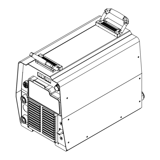
- Page 1 OM-234 199K 2012−10 Processes Multiprocess Welding Description Arc Welding Power Source EXTREME 425 CC/CV Auto-Line...
-
Page 3: Table Of Contents
TABLE OF CONTENTS SECTION 1 − SAFETY PRECAUTIONS - READ BEFORE USING ....... . . 1-1. -
Page 5: Section 1 − Safety Precautions - Read Before Using
SECTION 1 − SAFETY PRECAUTIONS - READ BEFORE USING som 2011−10 Protect yourself and others from injury — read, follow, and save these important safety precautions and operating instructions. 1-1. Symbol Usage DANGER! − Indicates a hazardous situation which, if Indicates special instructions. - Page 6 D Remove stick electrode from holder or cut off welding wire at FUMES AND GASES can be hazardous. contact tip when not in use. D Wear oil-free protective garments such as leather gloves, heavy Welding produces fumes and gases. Breathing shirt, cuffless trousers, high shoes, and a cap.
-
Page 7: Additional Symbols For Installation, Operation, And Maintenance
1-3. Additional Symbols For Installation, Operation, And Maintenance FIRE OR EXPLOSION hazard. BATTERY EXPLOSION can injure. D Do not install or place unit on, over, or near D Do not use welder to charge batteries or jump combustible surfaces. start vehicles unless it has a battery charging D Do not install unit near flammables. -
Page 8: California Proposition 65 Warnings
1-4. California Proposition 65 Warnings Welding or cutting equipment produces fumes or gases This product contains chemicals, including lead, known to which contain chemicals known to the State of California to the state of California to cause cancer, birth defects, or other cause birth defects and, in some cases, cancer. -
Page 9: Section 2 − Consignes De Sécurité − Lire Avant Utilisation
SECTION 2 − CONSIGNES DE SÉCURITÉ − LIRE AVANT UTILISATION fre_som_2011−10 Pour écarter les risques de blessure pour vous−même et pour autrui — lire, appliquer et ranger en lieu sûr ces consignes relatives aux précautions de sécurité et au mode opératoire. 2-1. - Page 10 Il reste une TENSION DC NON NÉGLIGEABLE dans LE SOUDAGE peut provoquer un les sources de soudage onduleur UNE FOIS incendie ou une explosion. l’alimentation coupée. Le soudage effectué sur des conteneurs fermés tels D Arrêter les convertisseurs, débrancher le courant électrique et que des réservoirs, tambours ou des conduites peut décharger les condensateurs d’alimentation selon les instructions provoquer leur éclatement.
-
Page 11: Dangers Supplémentaires En Relation Avec L'installation, Le Fonctionnement Et La Maintenance
ACCUMULATIONS LES BOUTEILLES peuvent exploser risquent de provoquer des blessures si elles sont endommagées. ou même la mort. Les bouteilles de gaz comprimé contiennent du gaz D Fermer l’alimentation du gaz comprimé en cas sous haute pression. Si une bouteille est endommagée, elle peut exploser. -
Page 12: Proposition Californienne 65 Avertissements
Les PIÈCES MOBILES peuvent RAYONNEMENT HAUTE causer des blessures. FRÉQUENCE (H.F.) risque provoquer des interférences. D Ne pas s’approcher des organes mobiles. D Ne pas s’approcher des points de coincement D Le rayonnement haute fréquence (H.F.) peut tels que des rouleaux de commande. provoquer des interférences avec les équi- pements de radio−navigation et de com- LES FILS DE SOUDAGE peuvent... -
Page 13: Principales Normes De Sécurité
2-5. Principales normes de sécurité Safety in Welding, Cutting, and Allied Processes, ANSI Standard Z49.1, Spectrum Way, Suite 100, Ontario, Canada L4W 5NS (phone: is available as a free download from the American Welding Society at 800-463-6727, website: www.csa-international.org). http://www.aws.org or purchased from Global Engineering Documents Safe Practice For Occupational And Educational Eye And Face Protec- (phone: 1-877-413-5184, website: www.global.ihs.com). - Page 14 OM-234 199 Page 10...
-
Page 15: Section 3 − Definitions
SECTION 3 − DEFINITIONS 3-1. Manufacturer Safety Symbols And Definitions Some symbols are found only on CE products. Warning! Watch Out! There are possible hazards as shown by the symbols. Safe1 2012−05 When power is applied failed parts can explode or cause other parts to explode. Safe26 2012−05 3-2. -
Page 16: Section 4 − Introduction
SECTION 4 − INTRODUCTION 4-1. Serial Number And Rating Label Location The serial number and rating information for this product is located on the rear panel. Use rating label to determine input power requirements and/or rated output. For future reference, write serial number in space provided on back cover of this manual. 4-2. -
Page 17: Duty Cycle And Overheating
4-4. Duty Cycle And Overheating Duty Cycle is percentage of 10 min- utes that unit can weld at rated load without overheating. If unit overheats, output stops, a Help message is displayed and cooling fan runs. Wait fifteen min- utes for unit to cool. Reduce amper- age or voltage, or duty cycle before welding. -
Page 18: Section 5 − Installation
SECTION 5 − INSTALLATION 5-1. Dimensions And Weight Hole Layout Dimensions 24 in. 11-3/4 in. (298 mm) (610 1-11/16 in. (42 mm) 17 in. 15-3/4 in. (400 mm) (432 mm) 19-3/32 in. (485 mm) 8-11/16 in. (221 mm) 1-17/32 in. (39 mm) 1/4-20 UNC -2B thread 12-1/2 in. -
Page 19: Remote 14 Receptacle Information
5-3. Remote 14 Receptacle Information Socket* Socket Information 24 volts AC. Protected by supplementary protect- or CB2. 24 VOLTS AC Contact closure to A completes 24 volts AC contactor control circuit. 115 volts AC. Protected by supplementary pro- C L N 115 VOLTS AC tector CB1. -
Page 20: Weld Output Receptacles And Selecting Cable Sizes
**Weld cable size (AWG) is based on either a 4 volts or less drop or a current density of at least 300 circular mils per ampere. ( ) = mm for metric use ***For distances longer than those shown in this guide, call a factory applications rep. at 920-735-4505 (Miller) or 1-800-332-3281 (Hobart). Ref. S-0007-J 2011−07 OM-234 199 Page 16... -
Page 21: Optional Gas Valve Operation And Shielding Gas Connection
5-5. Optional Gas Valve Operation And Shielding Gas Connection Obtain gas cylinder and chain to running gear, wall, or other station- ary support so cylinder cannot fall and break off valve. Cylinder Regulator/Flowmeter Install so face is vertical. Gas Hose Connection GAS IN Fitting has 5/8-18... -
Page 22: Electrical Service Guide
5-6. Electrical Service Guide Elec Serv 2011− NOTICE − INCORRECT INPUT POWER can damage this welding power source. Phase to ground voltage shall not exceed +10% of rated input voltage. Actual input voltage should not be 10% less than minimum and/or 10% more than maximum input voltages listed in table. If actual input voltage is outside this range, output may not be be available. - Page 23 Notes OM-234 199 Page 19...
-
Page 24: Connecting 1-Phase Input Power
5-7. Connecting 1-Phase Input Power =GND/PE Earth Ground Tools Needed: input1 2012−05 − Ref. 803 766-C OM-234 199 Page 20... - Page 25 5-7. Connecting 1-Phase Input Power (Continued) nected to any input power between 208 and Disconnect Device (switch shown in the Installation must meet all National and 575 VAC without removing cover to relink the OFF position) Local Codes − have only qualified per- power source.
-
Page 26: Connecting 3-Phase Input Power
5-8. Connecting 3-Phase Input Power = GND/PE Earth Ground Tools Needed: input2 2012−05 − Ref. 803 766-C OM-234 199 Page 22... - Page 27 5-8. Connecting 3-Phase Input Power (Continued) voltage available at site. This unit can be con- Input Conductors (L1, L2 And L3) Installation must meet all National and nected to any input power between 208 and Local Codes − have only qualified per- Disconnect Device Line Terminals 575 VAC without removing cover to relink the sons make this installation.
-
Page 28: Section 6 − Operation
SECTION 6 − OPERATION 6-1. Front Panel Controls Power Switch sults, place Arc Control in the maximum posi- When set towards maximum, short-circuit tion. amperage is increased at low arc voltage to The fan motor is thermostatically assist with arc starts as well as reduce stick- Remote 14 Receptacle controlled and only runs when cooling is ing while welding. -
Page 29: Meter Functions
6-2. Meter Functions The meters display the actual weld output values for approximately three seconds after the arc is broken. Mode Meter Reading At Idle Meter Reading While Welding Scratch 71.7 10.3 Start TIG Actual Volts (OCV) Preset Amps Actual Volts Actual Amps 14.1 10.3... -
Page 30: Lift-Arc Tig Procedure
6-4. Lift-Arc TIG Procedure With Process Switch in the Lift-Arc TIG position, start an arc as follows: TIG Electrode Workpiece Touch tungsten electrode to work- piece at weld start point, hold electrode to workpiece for 1-2 seconds, and slowly lift electrode. An arc will form when electrode is lifted. -
Page 31: Section 7 − Maintenance & Troubleshooting
SECTION 7 − MAINTENANCE & TROUBLESHOOTING 7-1. Routine Maintenance Disconnect power Maintain more often during before maintaining. severe conditions. n = Check Z = Change ~ = Clean l = Replace Replace Damaged Replace Cracked Torch Body Unreadable n Z l Labels Repair Or Replace... -
Page 32: Voltmeter/Ammeter Help Displays
7-3. Voltmeter/Ammeter Help Displays All directions are in reference to the front of the unit. All circuitry referred to is located inside the unit. Help 1 Display HE.L P−1 Indicates a malfunction in the prima- ry power circuit. If this display is shown, contact a Factory Authorized Service Agent. -
Page 33: Troubleshooting
7-4. Troubleshooting Trouble Remedy No weld output; unit completely inop- Place line disconnect switch in On position (see Sections 5-7 and 5-8). erative. Check and replace line fuse(s), if necessary, or reset circuit breaker (see Sections 5-7 and 5-8). Check for proper input power connections (see Sections 5-7 and 5-8). No weld output;... -
Page 34: Section 8 − Electrical Diagram
SECTION 8 − ELECTRICAL DIAGRAM Figure 8-1. Circuit Diagram OM-234 199 Page 30... - Page 35 256 230-A OM-234 199 Page 31...
-
Page 36: Section 9 − Parts List
SECTION 9 − PARTS LIST 803 690-K Figure 9-1. Parts Assembly OM-234 199 Page 32... - Page 37 Item Dia. Part Mkgs. Description Quantity Figure 9-1. Parts Assembly ....229 541 Wrapper (Includes Insulators and Safety Labels) ....
- Page 38 Item Dia. Part Mkgs. Description Quantity Figure 9-1. Parts Assembly (Continued) ....126 026 ..Label, Warning Electric Shock Can Kill Significant .
-
Page 39: Warranty
Warranty Effective January 1, 2012 (Equipment with a serial number preface of MC or newer) This limited warranty supersedes all previous manufacturers 90 Days — Parts warranties and is exclusive with no other guarantees or Accessory (Kits) warranties expressed or implied. Canvas Covers Induction Heating Coils and Blankets, Cables, and LIMITED WARRANTY −... - Page 40 Owner’s Record Please complete and retain with your personal records. Model Name Serial/Style Number Purchase Date (Date which equipment was delivered to original customer.) Distributor Address City State Contact the Delivering Carrier for: File a claim for loss or damage during shipment.