Table of Contents
Advertisement
Quick Links
Visit our website at
www.MillerWelds.com
PipeWorx 400 VRD
Welding System
(380-400 Volt Model)
OM-253 906H
Processes
MIG (GMAW) and Pulsed MIG
(GMAW-P) Welding
TIG (GTAW) Welding
Flux Cored (FCAW) Welding
Stick (SMAW) Welding
Multiprocess Welding
Description
Arc Welding Power Source
Wire Feeder
CE
File: MIG (GMAW)
2014−04
Advertisement
Table of Contents
Troubleshooting

Related Manuals for Miller PipeWorx 400 VRD


Summary of Contents for Miller PipeWorx 400 VRD
- Page 1 MIG (GMAW) and Pulsed MIG (GMAW-P) Welding TIG (GTAW) Welding Flux Cored (FCAW) Welding Stick (SMAW) Welding Multiprocess Welding Description Arc Welding Power Source Wire Feeder PipeWorx 400 VRD Welding System (380-400 Volt Model) File: MIG (GMAW) Visit our website at www.MillerWelds.com...
- Page 2 We know you don’t have time to do it any other way. That’s why when Niels Miller first started building arc welders in 1929, he made sure his products offered long-lasting value and superior quality.
- Page 3 DECLARATION OF CONFORMITY for European Community (CE marked) products. MILLER Electric Mfg. Co., 1635 Spencer Street, Appleton, WI 54914 U.S.A. declares that the product(s) identified in this declaration conform to the essential requirements and provisions of the stated Council Directive(s) and Standard(s).
-
Page 5: Table Of Contents
TABLE OF CONTENTS SECTION 1 − SAFETY PRECAUTIONS - READ BEFORE USING ....... . . 1-1. - Page 6 TABLE OF CONTENTS SECTION 6 − OPERATION ..............6-1.
-
Page 7: Section 1 − Safety Precautions - Read Before Using
SECTION 1 − SAFETY PRECAUTIONS - READ BEFORE USING som 2013−09 Protect yourself and others from injury — read, follow, and save these important safety precautions and operating instructions. 1-1. Symbol Usage DANGER! − Indicates a hazardous situation which, if Indicates special instructions. - Page 8 D Remove stick electrode from holder or cut off welding wire at FUMES AND GASES can be hazardous. contact tip when not in use. D Wear body protection made from durable, flame−resistant material Welding produces fumes and gases. Breathing (leather, heavy cotton, wool). Body protection includes oil-free these fumes and gases can be hazardous to your clothing such as leather gloves, heavy shirt, cuffless trousers, high health.
-
Page 9: Additional Symbols For Installation, Operation, And Maintenance
1-3. Additional Symbols For Installation, Operation, And Maintenance FIRE OR EXPLOSION hazard. MOVING PARTS can injure. D Do not install or place unit on, over, or near D Keep away from moving parts such as fans. combustible surfaces. D Keep all doors, panels, covers, and guards D Do not install unit near flammables. -
Page 10: California Proposition 65 Warnings
1-4. California Proposition 65 Warnings Welding or cutting equipment produces fumes or gases This product contains chemicals, including lead, known to which contain chemicals known to the State of California to the state of California to cause cancer, birth defects, or other cause birth defects and, in some cases, cancer. -
Page 11: Section 2 − Consignes De Sécurité − Lire Avant Utilisation
SECTION 2 − CONSIGNES DE SÉCURITÉ − LIRE AVANT UTILISATION fre_som_2013−09 Pour écarter les risques de blessure pour vous−même et pour autrui — lire, appliquer et ranger en lieu sûr ces consignes relatives aux précautions de sécurité et au mode opératoire. 2-1. - Page 12 D Ne pas raccorder plus d’une électrode ou plus d’un câble de D Avoir recours à des écrans protecteurs ou à des rideaux pour masse à une même borne de sortie de soudage. Débrancher le protéger les autres contre les rayonnements les éblouissements câble pour le procédé...
-
Page 13: Dangers Supplémentaires En Relation Avec L'installation, Le Fonctionnement Et La Maintenance
LES BOUTEILLES peuvent exploser DES PIECES DE METAL ou DES si elles sont endommagées. SALETES peuvent provoquer des blessures dans les yeux. Les bouteilles de gaz comprimé contiennent du gaz sous haute pression. Si une bouteille est D Le soudage, l’écaillement, le passage de la endommagée, elle peut exploser. - Page 14 LES CHARGES ÉLECTROSTATI- RAYONNEMENT HAUTE QUES peuvent endommager les cir- FRÉQUENCE (H.F.) risque cuits imprimés. provoquer des interférences. D Établir la connexion avec la barrette de terre D Le rayonnement haute fréquence (H.F.) peut avant de manipuler des cartes ou des pièces. provoquer des interférences avec les équi- pements de radio−navigation et de com- D Utiliser des pochettes et des boîtes antista-...
-
Page 15: Proposition Californienne 65 Avertissements
2-4. Proposition californienne 65 Avertissements Les équipements de soudage et de coupage produisent des Ce produit contient des produits chimiques, notamment du fumées et des gaz qui contiennent des produits chimiques plomb, dont l’État de Californie reconnaît qu’ils provoquent dont l’État de Californie reconnaît qu’ils provoquent des mal- des cancers, des malformations congénitales ou d’autres formations congénitales et, dans certains cas, des cancers. - Page 16 OM-253 906 Page 10...
-
Page 17: Section 3 − Definitions
SECTION 3 − DEFINITIONS 3-1. Additional Safety Symbols And Definitions Some symbols are found only on CE products. Warning! Watch Out! There are possible hazards as shown by the symbols. Safe1 2012−05 Wear dry insulating gloves. Do not touch electrode with bare hand. Do not wear wet or damaged gloves. Safe2 2012−05 Protect yourself from electric shock by insulating yourself from work and ground. - Page 18 Disconnect input plug or power before working on machine. Safe5 2012−05 When power is applied failed parts can explode or cause other parts to explode. Safe26 2012−05 Flying pieces of parts can cause injury. Always wear a face shield when servicing unit. Safe27 2012−05 Always wear long sleeves and button your collar when servicing unit.
- Page 19 Consult rating label for input power requirements. Safe34 2012−05 Drive rolls can injure fingers. Safe32 2012−05 Welding wire and drive parts are at welding voltage during operation − keep hands and metal objects away. Safe33 2012−05 Become trained and read the instructions before working on the machine or welding.
-
Page 20: Miscellaneous Symbols And Definitions
3-2. Miscellaneous Symbols And Definitions Some symbols are found only on CE products. Direct Current Alternating Amperage Voltage (DC) Current (AC) Gas Input Circuit Breaker To Power Source Shielded Metal Arc Positive Gas Output Welding (SMAW) Gas Tungsten Arc Welding (GTAW) / Protective Earth Work Connection Wire Feed... -
Page 21: Section 4 − Specifications
SECTION 4 − SPECIFICATIONS 4-1. Serial Number And Rating Label Location The serial number and rating information for this product is located on the front. Use rating label to determine input power requirements and/or rated output. For future reference, write serial number in space provided on back cover of this manual. 4-2. -
Page 22: Mig Duty Cycle And Overheating
4-3. MIG Duty Cycle and Overheating Duty Cycle is percentage of 10 min- utes that unit can weld at rated load without overheating. If unit overheats, thermostat(s) opens, output stops, and cooling fan runs. Wait fifteen minutes for unit to cool. Reduce amperage or duty cycle before welding. -
Page 23: Environmental Specifications
4-5. Environmental Specifications A. Wire Feeder IP Rating IP Rating IP21 This equipment is designed for indoor use and is not intended to be used or stored outside. 4-6. Important Information Regarding CE Products (Sold Within The EU) A. Information On Electromagnetic Fields (EMF) This equipment shall not be used by the general public as the EMF limits for the general public might be exceeded during welding. -
Page 24: Section 5 − Installation
SECTION 5 − INSTALLATION 5-1. Selecting a Location Movement Do not move or operate Tipping unit where it could tip. Special installation may be required where gasoline or Location volatile liquids are present − see NEC Article 511 or CEC Section 20. -
Page 25: Remote 14 Accessory Receptacle Information
5-2. Remote 14 Accessory Receptacle Information If a remote control is connected to the Remote 14 receptacle, the unit will automatically adjust output control to a primary/secondary configuration. In this configuration, the Amperage Adjust knob on the unit becomes the primary and sets the maximum amperage output of the unit. The remote control becomes the secondary and provides an amperage range of 0 to 100% based on the Amperage Adjust knob setting. -
Page 26: Turning On Remote 14 Receptacle Control For Stick
5-3. Turning On Remote 14 Receptacle Control For Stick Turn Off welding power source, disconnect input power, and check voltage on input capacitors accord- ing to Section 7-6 before proceeding. Stick Stick When this control is active and a current/contactor control Remote Remote... -
Page 27: Changing Wire Feed Speed From Inches Per Minute (Ipm) To Meters Per Minute (Mpm)
5-4. Changing Wire Feed Speed From Inches Per Minute (IPM) To Meters Per Minute (MPM) Turn Off welding power source, disconnect input power, and check voltage on input capacitors according to Section 7-6 before proceeding. PipeWorx Feeder Operator Interface Board Dip Switch Remove feeder wrapper. -
Page 28: Remote 14 Wire Feeder Control Receptacle Information
5-5. Remote 14 Wire Feeder Control Receptacle Information Remote 14 Feeder Control Socket* Socket Information 8, 12 24 volts AC. Protected by supplementary protector CB2. 24 VOLTS AC 24 volts AC return. Connected to chassis common. Completes 24 volts AC power supply circuit to feeder. -
Page 29: Supplementary Protector Cb2
5-6. Supplementary Protector CB2 Supplementary Protector CB2 CB2 protects the 24 volts ac power supply to the wire feeder (see Section 5-5). Press button to reset supplementary protector. 254 085-A OM-253 906 Page 23... -
Page 30: Volts Ac Single Receptacle Rc2 And Supplementary Protector
5-7. 115 Volts AC Single Receptacle RC2 And Supplementary Protector 115 V 10 A AC Receptacle RC2 (Cooler Power Supply Only When Power Source Is On) RC2 is designated receptacle intended only for supplying AC power PipeWorx cooler. Power is available at receptacle RC2 only when the power source is on. -
Page 31: Lifting Eye On Power Source
5-8. Lifting Eye On Power Source Turn Off welding power source, disconnect input power. Lifting Eye The wire feeder allows access to the lifting eye on the power source. The entire welding system as shown with cable hangers, cooler with coolant, dual feeder, and running gear can be lifted with the lifting eye. -
Page 32: Electrical Service Guide
5-9. Electrical Service Guide Elec Serv 2014−01 NOTICE − INCORRECT INPUT POWER can damage this welding power source. This welding power source requires a CONTINUOUS supply of input power at rated frequency(+10%) and voltage (+10%). Phase to ground voltage shall not exceed +10% of rated input voltage. Do not use a genera- tor with automatic idle device (that idles engine when no load is sensed) to supply input power to this welding power source. - Page 33 Notes OM-253 906 Page 27...
-
Page 34: Connecting 3-Phase Input Power
5-10. Connecting 3-Phase Input Power = GND/PE Earth Ground L1 L2 L3 Tools Needed: 5/16 in. Input3 2011−03 − 254 080-A OM-253 906 Page 28... - Page 35 5-10. Connecting 3-Phase Input Power (Continued) national, state, and local electrical codes. If Connect input conductors L1 (U), L2 (V) and Installation must meet all National applicable, use lugs of proper amperage L3 (W) to welding power source line and Local Codes − have only qualified capacity and correct hole size.
-
Page 36: Installing Optional Handles, Running Gear And Cooler
5-11. Installing Optional Handles, Running Gear And Cooler Turn Off welding power source, Tools Needed: disconnect input power. 1/2 in. Running Gear 234 359 Cooler Wheel 163 463 (2) Flat Washer 602 250 (4) 5/16 in. Retaining Ring 121 614 (2) Install wheels on cylinder tray as shown. -
Page 37: Assembling And Installing Cable Hanger
5-12. Assembling And Installing Cable Hanger Bracket Tube Cap (4) Cable Holder Tube (2) Install caps in tubes. Assemble cable holder tubes to bracket using supplied hardware. Place cable holder assembly on top of power source or cart and set wire feeder on cable hanger. -
Page 38: Proper Ring Terminal Connection To Volt Sense Lead
5-13. Proper Ring Terminal Connection To Volt Sense Lead If volt sense lead is cut or broken at end Jacket Center Conductor 10 ga with ring terminal, be sure that new ring ter- Insulated Tape Or Heat-Shrink minal is connected as shown. Tubing Ring Terminal 1/2 in. -
Page 39: Weld Output Terminals And Selecting Cable Sizes* Recommended For Pipeworx 400
**Weld cable size (AWG) is based on either a 4 volts or less drop or a current density of at least 300 circular mils per ampere. ( ) = mm for metric use. ***For distances longer than those shown in this guide, call a factory applications rep. at 920-735-4505 (Miller) or 1-800-332-3281 (Hobart) Ref. S-0007-K 2013−09 OM-253 906 Page 33... -
Page 40: Connecting Weld Output Cables
5-16. Connecting Weld Output Cables Do not place anything between weld cable terminal and copper bar. Tools Needed: 19 mm (3/4 in.) Incorrect Installation 803 778-B Weld Output Terminal weld output terminal and secure with nut so Turn off power before connecting to that weld cable terminal is tight against weld output terminals. -
Page 41: Typical Connection Diagram For Mig (Gmaw) Equipment With Feeder On Power Source
5-17. Typical Connection Diagram For MIG (GMAW) Equipment With Feeder On Power Source 254 079-A Gas Hose of gas hose to gas solenoid connector on Do not put feeder where welding rear of feeder or Y-hose for dual wire feeder. wire hits cylinder. -
Page 42: Typical Connection Diagram For Mig (Gmaw) Equipment With Feeder On Cart
5-18. Typical Connection Diagram For MIG (GMAW) Equipment With Feeder On Cart 254 086-A Gas Cylinder connect remaining end of gas hose to gas Do not put feeder where welding solenoid connector on rear of feeder or wire hits cylinder. Locate end of composite cable where gas Y-hose for dual wire feeder. -
Page 43: Wire Feeder Rear Panel Connections And Rotating Drive Assembly
5-19. Wire Feeder Rear Panel Connections And Rotating Drive Assembly 14-Pin Control Cable Shielding Gas Valve Fittings Requires fitting with 5/8-18 right-hand threads. Connect customer-supplied gas hose. Weld Cable Terminal Jumper Weld Cable From Right Side Drive Assembly (Dual Model Only) Weld Cable Drive Assembly Drive Assembly Rotation... -
Page 44: Gun Trigger Receptacle
5-20. Gun Trigger Receptacle Left Gun Trigger Receptacle Right Gun Trigger Receptacle RC3 (Dual Model Only) Connect gun trigger plug to appropriate receptacle on feeder. 254 083-A Notes OM-253 906 Page 38... -
Page 45: Installing And Threading Welding Wire
5-21. Installing And Threading Welding Wire Install wire guides and Install wire spools. Adjust tension nuts so anti-wear guide. wire is taut when wire feed stops. Install drive rolls. Pressure Indicator Pressure Scale Adjust Rear Pressure Rolls Adjust Front Rolls No Wire Slip Wire Slips NONCONDUCTIVE... -
Page 46: Voltage Sensing Lead And Work Cable Connections For Multiple Welding Arcs
5-22. Voltage Sensing Lead And Work Cable Connections For Multiple Welding Arcs A. Ideal Setup 805 289-B Welding Power Source signal to the welding system. Use of this This arrangement is an ideal setup for lead is critical stable welding supporting separate voltage feedback to Composite Cable performance. - Page 47 B. Bad Setup 805 290-B Welding Power Source Workpiece across the workpiece will not be measured correctly for the voltage feedback signal. Composite Cable This arrangement is a bad setup due to Voltage feedback to the welding power sensing leads being directly in the current Work Cable sources will not be correct at either sense flow path of the welding arc.
-
Page 48: Arranging Welding Cables To Reduce Welding Circuit Inductance
5-23. Arranging Welding Cables To Reduce Welding Circuit Inductance Welding Power Source Composite Cable Work Cable Volt Sense Lead Ideal Wire Feeder Workpiece The method used to arrange cables has significant affect welding performance. As an example, Pro-Pulse and RMD welding processes can produce high welding circuit inductance depending on cable length and arrangement. -
Page 49: Typical Connection Diagram For Stick (Smaw) Equipment
5-24. Typical Connection Diagram For Stick (SMAW) Equipment Welding Power Source Work (−) Weld Cable Stick (+) Weld Cable Workpiece Electrode Holder Volt Sense Lead Attach volt sense lead to work clamp and attach work clamp as close to arc as possible. 115V 10A AC Receptacle (Cooler Power Supply Only) READ OWNER'S MANUAL... -
Page 50: Typical Connection Diagram For Two Piece Air-Cooled Tig (Gtaw) Torch
5-25. Typical Connection Diagram For Two Piece Air-Cooled TIG (GTAW) Torch (Using Gas Solenoid Inside Power Source) Welding Power Source Gas Hose TIG (−) Weld Cable Work (+) Weld Cable Workpiece TIG Torch Volt Sense Lead Remote Foot Control (Optional) Attach volt sense lead to work clamp and attach work clamp as close to arc as possible. -
Page 51: Typical Connection Diagram For One Piece Air-Cooled Tig (Gtaw) Torch
5-26. Typical Connection Diagram For One Piece Air-Cooled TIG (GTAW) Torch (Using Gas Solenoid Inside Power Source) Welding Power Source Gas Hose 237 415 (Short Black Hose Supplied With Power Source) TIG Block (Customer Supplied) TIG (−) Weld Cable Work (+) Weld Cable Workpiece TIG Torch Volt Sense Lead... -
Page 52: Typical Connection Diagram For Liquid-Cooled Tig (Gtaw) Torch
5-27. Typical Connection Diagram For Liquid-Cooled TIG (GTAW) Torch (Using Gas Solenoid Inside Power Source) Welding Power Source Gas Hose TIG Block (Customer Supplied) Coolant Out Hose 237 416 (Short Red Hose Supplied With Cooler) TIG (−) Weld Cable Coolant Return Hose Work (+) Weld Cable Workpiece TIG Torch... -
Page 53: Section 6 − Operation
SECTION 6 − OPERATION 6-1. Operational Terms The following is a list of terms and their definitions as they apply to this interface unit: General Terms: 98/2 Ox Gas mixture of 98% Argon and 2% O Amps Indicates average amperage while welding and holds the value for 10 seconds at end of weld. Arc Control The adjustment of arc cone width and arc characteristics in the RMD and Pulse processes. - Page 54 6-1 . Operational Terms (Continued) Pulse An advanced pulse spray transfer process suited for the fill and cap passes on pipe. The Pulse process utilizes (Pro-Pulset) constant current ramps with constant voltage control of peaks and backgrounds. Adaptive response is controlled by peak and minimum current levels.
-
Page 55: Welding Power Source Controls
6-2. Welding Power Source Controls A. Front Panel Controls 252 613-B Stick Electrode Type Select Button 14 Wire Diameter Select Button Only illuminated controls can be Ammeter Display changed or adjusted. 15 Gas Type Select Button Memory Card Busy Indicator Amperage Adjust Knob 16 Gas Selection Table Memory Card Save Button... -
Page 56: Memory Card Slot
6-3. Memory Card Slot Memory Card Slot This is the memory card slot. The memory card slot uses an SD memory card. A memory card can be inserted into the slot and used for storing and retrieving operator settings, providing custom MIG type weld process data, and loading firmware updates to the unit. - Page 57 B. Using Optional Memory Card Memory Card Insertion Lift and hold memory card access cover open. Insert memory card into slot (push card all the way into slot and then release). Close memory card access cover. Memory Card Removal Lift and hold memory card access cover open. Push in and release memory card to eject card.
- Page 58 D. Stick And TIG Welding Process Controls Stick Process Select Button Press and release this button to activate the stick welding process controls. The STICK text below the button illuminates as well as the active stick electrode type text and the swoosh above the amperage adjust knob. The operator must select the desired stick electrode type and adjust the amperage knob to the appropriate setting within a range from 40 to 400 amps.
- Page 59 Ramp down time − 0.0 to 10.0 seconds Final amperage − 10 to 350 amps Final time − 0.0 to 10.0 seconds (2T only) Postflow time − 0 to 60 seconds 2T Trigger Operation When in the 2T trigger mode the following weld sequence will occur: Press and hold the TIG torch trigger to start the sequence.
- Page 60 Gas Selection Table The gas selection table provides the available shielding gas selections. For any MIG process except FCAW, gas selections are structured into columns based first on WIRE TYPE type and then on MIG process selections. The gas type text illuminates to indicate the active gas selection. Shielding gas selections are as follows: C8-C15 (92% Argon/8% CO to 85% Argon/15% CO...
-
Page 61: Tig Sequence Control
6-4. TIG Sequence Control 252 613-B 2T Trigger Icon Initial Amperage Indicator Final Amperage Indicator 4T Trigger Icon Ramp-Up Indicator Postflow Indicator Preflow Indicator Ramp-Down Indicator TIG Sequence Control Set-Up Button OM-253 906 Page 55... -
Page 62: Stick Process Selection Setup Example
6-5. Stick Process Selection Setup Example Ref. 252 613-B Stick Process Active Amperage Setting 350A Only illuminated controls can be changed or adjusted. EXX10 Electrode Type Selected Memory Location 1 Active OM-253 906 Page 56... -
Page 63: Tig Process Selection Setup Example
6-6. TIG Process Selection Setup Example Ref. 252 613-B TIG Process Active Amperage Setting 350A Only illuminated controls can be changed or adjusted. HF Start Method Selected Memory Location 2 Active OM-253 906 Page 57... -
Page 64: Mig Process Selection Setup Example 1
6-7. MIG Process Selection Setup Example 1 252 613-B Carbon Steel Wire Type Selected Trigger Select On Only illuminated controls can be changed or adjusted. 0.9 Wire Diameter Selected Side Select Left MIG Process Active C8-C15 Gas Type Selected Memory Location 3 Active OM-253 906 Page 58... -
Page 65: Mig Process Selection Setup Example 2
6-8. MIG Process Selection Setup Example 2 252 613-B Stainless Steel Wire Type Selected Trigger Select On Only illuminated controls can be 0.9 Wire Diameter Selected Side Select Left changed or adjusted. Pro-Pulse MIG Process Active 98/2 Ox Gas Type Selected Memory Location 4 Active OM-253 906 Page 59... -
Page 66: Wire Feeder Controls
6-9. Wire Feeder Controls A. Front Panel Controls 252 620-C Right Side Controls Select Button* 10 Trigger Hold Select Button Only illuminated controls can be Wire Feed Speed Display 11 Purge Button changed or adjusted. Wire Feed Speed Adjust Knob 12 Memory Select Button And Location Left Side Controls Select Button Indicator... - Page 67 Left Side Controls Select Button Press and release this button to activate the wire feeder left side controls. The LEFT text below the button will illuminate and the swooshes above the volts/arc length adjustment knob and wire feed speed adjustment knob will illuminate. See Section 6-2 for the procedure to select the appropriate MIG process type parameters.
- Page 68 Wire Feed Speed Adjust Knob Use this knob to adjust the desired wire feed speed setting [1.3 to 19.8 mpm (50 to 780 ipm)]. Rotating the knob clockwise increases wire feed speed and counter-clockwise decreases wire feed speed. Wire feed speed adjustment is active when the swoosh above the knob is illuminated. The setting can be different for left and right sides and MIG process type, and the unit will hold these settings for both sides.
-
Page 69: Preflow And Postflow Adjustment
6-10. Preflow And Postflow Adjustment Postflow will not function without an arc initiation. Preflow and Postflow times can be configured for each of the TIG, Wire Feeder Left and Wire Feeder Right outputs. These times are global settings (i.e. all memory slots share the same three preflow and postflow settings; it is not possible to set different postflow times between memory slots). The unit is shipped in the standard configuration (“Std”... -
Page 70: Wire Feeder Left Side Active Setup Example
Unit will display PSt on the Voltage display. Adjust postflow time to desired value by rotate the Wire Feed Speed knob. Available selections include Std and numeric values from 0 to 60 seconds. Press any button to return to the normal display. 6-11. -
Page 71: Wire Feeder Right Side Active Setup Example (Dual Feeder Only)
6-12. Wire Feeder Right Side Active Setup Example (Dual Feeder Only) 252 620-C Right Side Controls Active Trigger Hold On Only illuminated controls can be changed or adjusted. Pulse Process Selected Memory Location 2 Active OM-253 906 Page 65... -
Page 72: Wire Feeder Non-Mig Setup Example
6-13. Wire Feeder Non-MIG Setup Example 252 620-C Non-MIG Process Selected Memory Location 3 Active Only illuminated controls can be changed or adjusted. OM-253 906 Page 66... -
Page 73: Wire Feeder Timed Purge Example
6-14. Wire Feeder Timed Purge Example 252 620-C Pressed Simultaneously Purge Time Remaining Display Only illuminated controls can be Purge Time Setting Adjustment Knob changed or adjusted. Purge And Trigger Hold Buttons OM-253 906 Page 67... -
Page 74: Wire Feeder Auto Jog Example
6-15. Wire Feeder Auto Jog Example 15.3 252 620-C Simultaneously Jog Wire Feed Speed Adjustment Knob Only illuminated controls can be Jog Feet Adjustment Knob Jog Wire Feed Speed Display changed or adjusted. Jog And Trigger Hold Buttons Pressed Jog Feet Remaining Display OM-253 906 Page 68... -
Page 75: Basic Parameters For Pipeworx 400
6-16. Basic Parameters For PipeWorx 400 Steel Wire Size Wire Feed Speed Arc Length Shielding Gas Process 2.5-8.9 w/5.1 Nominal +3.0 to −3.0 C8-C15 w/zero Nominal 2.5-8.9 w/5.1 Nominal +3.0 to −3.0 w/zero Nominal 2.5-8.9 w/5.1 Nominal +3.0 to −3.0 w/zero Nominal 3.8-8.9 w/5.1 Nominal +3.0 to −3.0... - Page 76 Steel Wire Size Wire Feed Speed Arc Length Shielding Gas Process 2.5-19.8 w/5.1 Nominal +3.0 to −3.0 C8-C15 w/zero Nominal 2.5-19.8 w/5.1 Nominal +3.0 to −3.0 w/zero Nominal 2.5-19.8 w/4.4 Nominal +3.0 to −3.0 C8-C15 w/zero Nominal ProPulse Carbon Using A Positioner (Rolling The Pipe) 2.5-19.8 w/4.4 Nominal...
- Page 77 Stainless Steel Wire Size Wire Feed Speed Arc Length Shielding Gas Process 2.5-8.9 W/5.1 Nominal +3.0 to −3.0 w/zero Nominal 2.5-8.9 W/5.1 Nominal +3.0 to −3.0 98/2 Ox w/zero Nominal 2.5-7.6 w/4.4 Nominal +3.0 to −3.0 w/zero Nominal RMD Stainless Steel 2.5-7.6 w/4.4 Nominal +3.0 to −3.0 98/2 Ox...
-
Page 78: Lift-Arc And Hf Tig Start Procedures
Flux Core Wire Size Rolling Pipe/In Position Voltage Shielding Gas Process Wire Feed Speed 1.3-19.8 w/6.4 Nominal* 24.5-32 w/25.0 Nominal Not Dependent Flux Core/GMAW Dependent Note: Arc Length − Length of arc from end of wire to weld puddle. Wire feed speed and voltage are synergic for the RMD and ProPulse processes. -
Page 79: Section 7 − Maintenance And Troubleshooting
SECTION 7 − MAINTENANCE AND TROUBLESHOOTING 7-1. Routine Maintenance Disconnect power before maintaining. n = Check ~ = Clean l = Replace Every Months l Unreadable Labels ~ Weld Terminals nl Weld Cable l Cracked Parts n 14-Pin Cord n Gas Hose and Fittings n Gun Cable l Cracked Electrode l Cracked Torch Body... -
Page 80: Restoring Factory Defaults
7-3. Restoring Factory Defaults Full System A full factory reset can be accomplished by pressing memory location buttons 1 and 4 on the power source simultaneously for more than four seconds. The display will show rSt and then go to dashes when the reset is complete. Memory Location See Section 6-2 C2 the reset procedure. - Page 81 Calibrate STICK voltage as follows: Connect voltmeter from STICK stud (front left) to Work stud (front center). Press memory 3 button on the power source front panel. Open circuit voltage should now be present from STICK output stud to the Work stud.
-
Page 82: Removing Right Side Panel And Measuring Input Capacitor Voltage
7-6. Removing Right Side Panel and Measuring Input Capacitor Voltage Turn Off welding power source, disconnect input power. Significant DC voltage can remain on capacitors after unit is Off. Always check the voltage as shown to be sure the input capacitors have discharged before working on unit. -
Page 83: Welding Power Source And Feeder Diagnostic Help Codes
7-7. Welding Power Source And Feeder Diagnostic Help Codes Display Example Display Code Fault Description Primary Power Circuit Over Current Indicates a malfunction in the primary power circuit. If this code appears on the display, contact the nearest Factory Authorized Service Agent. - Page 84 Motor Low Bus Indicates input primary line voltage is too low. Increase primary line voltage to at least 90% of specified nominal voltage. If this code continues to appear on the display, contact the nearest Factory Authorized Service Agent. Button Stuck Feeder Indicates button is stuck on the feeder upon feeder power up.
-
Page 85: Troubleshooting Welding Power Source/Wire Feeder Issues
7-8. Troubleshooting Welding Power Source/Wire Feeder Issues If the welding power source and wire feeder are NOT responding after everything is connected, follow the items listed below before contacting the nearest factory-authorized service agent: Welding power source is plugged in and there is no power after turning on unit. If unit is directly connected to a line disconnect box or plugged into a receptacle from a line disconnect box, be sure that the line disconnect switch or main breaker is in the ON position. -
Page 86: Welding Power Source Troubleshooting
7-9. Welding Power Source Troubleshooting Disconnect power before troubleshooting. Trouble Remedy No weld output; unit completely in- Place line disconnect switch in On position (see Section 5-10). operative. Check and replace line fuse(s), if necessary, or reset circuit breaker (see Section 5-10). Check for proper input power connections (see Section 5-10). -
Page 87: Wire Feeder Troubleshooting
7-10. Wire Feeder Troubleshooting Disconnect power before troubleshooting. Trouble Remedy Wire feeds, shielding gas flows, but Check cable connections. Check cables for continuity, and repair or replace cables if necessary. electrode wire is not energized. Wire feeder is on, display does not light Check and reset circuit breaker at welding power source. -
Page 88: Section 8 − Electrical Diagram
SECTION 8 − ELECTRICAL DIAGRAM Figure 8-1. Circuit Diagram For Welding Power Source OM-253 906 Page 82... - Page 89 254 310-B OM-253 906 Page 83...
- Page 90 Figure 8-2. Circuit Diagram For Single Or Dual Wire Feeder OM-253 906 Page 84...
- Page 91 236 220-F OM-253 906 Page 85...
-
Page 92: Section 9 − High Frequency
SECTION 9 − HIGH FREQUENCY 9-1. Welding Processes Requiring High Frequency High-Frequency Voltage TIG − helps arc jump air gap between torch and workpiece and/ or stabilize the arc. Work high_freq 5/10 − S-0693 9-2. Installation Showing Possible Sources Of HF Interference Weld Zone 11, 12 50 ft... -
Page 93: Recommended Installation To Reduce Hf Interference
9-3. Recommended Installation To Reduce HF Interference Weld Zone 50 ft (15 m) 50 ft (15 m) Ground all metal ob- jects and all wiring in welding zone using #12 AWG wire. Ground workpiece if required by Nonmetal codes. Building Best Practices Followed Metal Building Ref. -
Page 94: Section 10 − Parts List
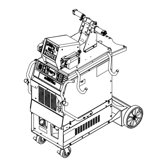
SECTION 10 − PARTS LIST Hardware is common and not available unless listed. 254 067-B Figure 10-1. Main Assembly OM-253 906 Page 88... - Page 95 Item Dia. Part Mkgs. Description Quantity Figure 10-1. Main Assembly ... . +250832 Panel, Rear ............
- Page 96 Item Dia. Part Mkgs. Description Quantity Figure 10-1. Main Assembly (Continued) ... . . 210866 Terminal, Pwr Output Black ..........
- Page 97 Item Dia. Part Mkgs. Description Quantity Figure 10-1. Main Assembly (Continued) ... . . 233483 Cover, Top ............
- Page 98 Hardware is common and not available unless listed. 10 11 31 − Figure 10-4 254 082-B Figure 10-2. Single Wire Feeder OM-253 906 Page 92...
- Page 99 Item Dia. Part Mkgs. Description Quantity Figure 10-2. Single Wire Feeder ... . +234243 Wrapper, Single Feeder ..........
- Page 100 Item Dia. Part Mkgs. Description Quantity Figure 10-2. Single Wire Feeder (Continued) ......Rear Panel Assy, Single Feeder (Includes) .
- Page 101 Hardware is common and not available unless listed. 254 081-B Figure 10-3. Dual Wire Feeder OM-253 906 Page 95...
- Page 102 Item Dia. Part Mkgs. Description Quantity Figure 10-3. Dual Wire Feeder ... . . 142838 Bracket, Mtg Spool RH ..........
- Page 103 Item Dia. Part Mkgs. Description Quantity Figure 10-3. Dual Wire Feeder (Continued) ......Rear Panel Assy, Dual Feeder (Includes) .
- Page 104 Hardware is common and not available unless listed. See Table 10-1 For Drive Roll & Wire Guide Kits 803 790-A Figure 10-4. Drive Assembly, Wire Item Dia. Part Mkgs. Description Quantity Figure 10-4. Drive Assembly, Wire (Figure 10-2 Item 31 And Figure 10-3 Items 30 And 31) .
- Page 105 Item Dia. Part Mkgs. Description Quantity Figure 10-4. Drive Assembly, Wire (Continued) ..... 203 642 Pressure Arm, R & Vert L 4 Roll (Includes) .
- Page 106 Table 10-1. Drive Roll And Wire Guide Kits Wire Size V-GROOVE VK-GROOVE Intermediate Inlet Guide Guide Fraction Metric 4 Roll Kit Drive Roll 4 Roll Kit Drive Roll .035 in. 0.9 mm 150 993 149 518 151 026 053 700 151 052 132 958 .040 in.
- Page 107 Hardware is common and not available unless listed. 9 10 805 302-b Figure 10-5. Running Gear OM-253 906 Page 101...
- Page 108 Item Dia. Part Mkgs. Description Quantity Figure 10-5. Running Gear ... . . 236827 Handle, Power Source ..........
- Page 109 Hardware is common and not available unless listed. 805 301-A / Ref. 239 780-B Figure 10-6. Composite Cables Quantity Model Item Dia. Part 5 ft 25 ft 50 ft Mkgs. Description 300 367 300 454 300 456 Figure 10-6. Composite Cables .
- Page 110 Hardware is common and not available unless listed. 805 148-B Figure 10-7. Cable Hanger Assembly Item Dia. Part Mkgs. Description Quantity Figure 10-7. Cable Hanger Assembly ... . . 285304 Bracket, Cable Holder w/Edge Trim .
- Page 111 Hardware is common and not available unless listed. 805 318-A Figure 10-8. Feeder Cart OM-253 906 Page 105...
- Page 112 Item Dia. Part Mkgs. Description Quantity Figure 10-8. Feeder Cart ... . . 217255 Slide, Drawer ............
- Page 113 Effective January 1, 2014 (Equipment with a serial number preface of ME or newer) This limited warranty supersedes all previous Miller warranties and is exclusive with no other guarantees or warranties expressed or implied. Warranty Questions? LIMITED WARRANTY − Subject to the terms and conditions below, 6 Months —...
- Page 114 Contact the Delivering Carrier to: File a claim for loss or damage during shipment. For assistance in filing or settling claims, contact your distributor and/or equipment manufacturer’s Transportation Department. ORIGINAL INSTRUCTIONS − PRINTED IN USA 2014 Miller Electric Mfg. Co. 2014−01...