Table of Contents
Advertisement
Quick Links
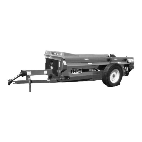
MANURE SPREADER
OPERATOR'S MANUAL
Revision #1
Starting Serial #311733
H&S MANUFACTURING CO.,INC.
P.O. BOX 768 (715) 387-3414 FAX (715) 384-5463
WARNING
Manufactured By
MARSHFIELD, WISCONSIN 54449
175
READ AND UNDERSTAND THIS MANUAL
BEFORE OPERATING THIS EQUIPMENT.
UNSAFE OPERATION OR MAINTENANCE OF
THIS EQUIPMENT CAN RESULT IN SERIOUS
INJURY OR DEATH.
HSMFG0913
Part #59919
Advertisement
Table of Contents

Related Manuals for H&S 175


Summary of Contents for H&S 175
- Page 1 MANURE SPREADER OPERATOR’S MANUAL READ AND UNDERSTAND THIS MANUAL BEFORE OPERATING THIS EQUIPMENT. UNSAFE OPERATION OR MAINTENANCE OF THIS EQUIPMENT CAN RESULT IN SERIOUS WARNING INJURY OR DEATH. Revision #1 Starting Serial #311733 HSMFG0913 Part #59919 Manufactured By H&S MANUFACTURING CO.,INC. P.O.
-
Page 2: Table Of Contents
CONTENTS Warranty & Warranty Registration Card ..........1-2 Manufacturers Statement . -
Page 5: Dealer Pre-Delivery Checklist
DEALER PRE-DELIVERY CHECK LIST AFTER COMPLETION, DEALER SHOULD REMOVE AND RETAIN FOR RECORDS After the Manure Spreader has been completely set-up, check to be certain it is in correct operating order before delivering to the customer. The following is a list of points to inspect. Check off each item as you have made the proper adjustments and found the item operating satisfactorily. - Page 6 Intentionally Left Blank...
-
Page 7: Dealer Delivery Checklist
DEALER DELIVERY CHECK LIST AFTER COMPLETION, DEALER SHOULD REMOVE AND RETAIN FOR RECORDS This check list that follows is an important reminder of valuable information that should be passed on to the customer at the time this Manure Spreader is delivered. Check off each item as you explain it to the customer. - Page 8 Intentionally Left Blank...
-
Page 9: Safety Information - Be Alert Symbol
SAFETY INFORMATION YOUR SAFETY IS INVOLVED. ALERT! THIS SYMBOL IS USED THROUGHOUT THIS BOOK WHENEVER YOUR PERSONAL SAFETY IS INVOLVED. TAKE TIME TO BE CAREFUL. REMEMBER: THE CAREFUL OPERATOR IS THE BEST OPERATOR. MOST ACCIDENTS ARE CAUSED BY HUMAN ERROR. CERTAIN PRECAUTIONS MUST BE OBSERVED TO PREVENT THE POSSIBILITY OF INJURY OR DAMAGE. -
Page 10: Safety Information - Explanation Of Safety Signs
SAFETY INFORMATION Keep signs in good condition. Immediately replace any missing or damaged signs. RECOGNIZE SAFETY INFORMATION This is the safety-alert symbol. When you see this symbol on your machine or in this manual, be alert to the potential for personal injury. Follow recommended precautions and safe operating practices. -
Page 11: Safety Decals
SAFETY INFORMATION... - Page 12 SAFETY INFORMATION -10-...
-
Page 13: Safety Information - Warning - Owner Must Read And Understand
SAFETY INFORMATION TRACTOR: This operators manual uses the term “Tractor” when identifying the power or the towing source. W A R N I N G TO PREVENT SERIOUS INJURY OR DEATH BEFORE YOU ATTEMPT TO OPERATE THIS EQUIPMENT, READ AND STUDY THE FOLLOWING INFORMATION. -
Page 14: Cap Screw Torque Values
-12-... -
Page 15: Set-Up & Assembly
SET-UP & ASSEMBLY NOTE: Determine right or left side of the Manure Spreader by viewing it from the rear. If instructions or parts lists call for hardened bolts, refer to the Cap Screw Torque Value Chart. PREPARING MANURE SPREADER The Manure Spreader may be shipped without the wheels/tires installed. 1. -
Page 16: Preparing For Operation
PREPARING FOR OPERATION TRACTOR CONNECTIONS Tractor Hitch Fasten the spreader hitch to the drawbar with a hitch pin with a safety locking device. Remove the weight from the jack (jack is not to be used when spreader is loaded). Remove jack from pipe mount and place on convenient storage mount located on the left front of spreader. -
Page 17: Operation
OPERATION LOADING In freezing weather, make certain that hydraulic tail gate (if equipped with one) is not frozen to the sides or on the floor of the spreader. Make sure the apron chain is not frozen to the spreader floor or any lumps of manure are frozen to the floor. -
Page 18: Adjustments
ADJUSTMENTS DRIVE CHAIN Shields Removed For Clarity To adjust front drive chain, slightly loosen bolts holding pillow block bearing at rear of front jack shaft. Loosen jam nut on tightener rod. Turn adjusting nut (located at the right hand front side of spreader) clockwise. There should be 1/2”... - Page 19 ADJUSTMENTS APRON 1. Adjust the apron by loosening the mounting bolts on the chain slides on the outside of the frame. Mounting bolts shown in the drawing. 2. Tighten the adjusting bolts until the apron has no sag between the rear drive sprockets and chain slides under spreader.
-
Page 20: Service
SERVICE SHEAR BOLTS - Main Drive The beater and the apron drive are protected by one shear bolt located on the front end of the side drive shaft (left side of spreader). Two spare shear bolts are provided. Shearing of the bolts is normally due to foreign objects in the manure or starting the spreader PTO too quickly with high tractor RPM’s. - Page 21 SERVICE BEATER Periodically inspect the beater for wear or damage. Damaged or broken teeth will cause excessive machine vibration. The beater paddles are welded to the beater tube, replacement of these paddles, should it be necessary, should be performed by authorized service personnel who are competent welders. Addition of beater tips should be installed as a complete set, to maintain beater balance.
-
Page 22: Optional Equipment
OPTIONAL EQUIPMENT REAR PAN The rear pan shown below is optional equipment. REAR PAN SEMI-LIQUID HYDRAULIC ENDGATE The semi-liquid hydraulic endgate is also optional. The rear pan and hydraulic endgate may be used together on this model. HYDRAULIC ENDGATE TOP BEATER The top beater shown below is optional equipment. -
Page 23: Lubrication Guide
LUBRICATION The operator should become familiar with all lubrication points and establish a systematic routine to insure complete and quick lubrication of the machine. GENERAL INFORMATION IMPORTANT: Catch and dispose of fluid per local waste disposal regulations whenever service is performed on hydraulic components, valves, cylinders, hoses, etc. - Page 24 LUBRICATION GREASE ZERK LOCATION - Grease every 20 Hours (3) PTO Shaft (1) Front Jack Shaft Bearing (1) Rear Jack Shaft Bearing (1) Front Side Shaft Bearing (1) Middle Side Shaft Bearing (2) Rear drive shaft (LH is a remote fitting) (1) Rear drive shaft shear sprocket (1) Beater bearing (RH side) (2) Hydraulic endgate arms (If equipped with a Hydraulic Endgate)
-
Page 25: Decal Location
DECAL LOCATION Your H&S Manure Spreader was manufactured with operator safety in mind. Located on the Manure Spreader are various decals to aid in operation, and warn of danger or caution areas. Pay close attention to all decals on your Manure Spreader. DO NOT REMOVE ANY OF THESE DECALS. - Page 26 DECAL LOCATION 82602 12794 9194A 1494K 11593A 93466 71188B 1494K 8390 71494A 1494K 1494J 1494L BEHIND SHIELD 11593A 8391 8389 54033 72203A 9194B DCAMB 1494J 82793 1494B 9194A 93466 1494L -24-...
- Page 27 DECAL LOCATION 54033 72203A 8389 DCRED 1494J 9194B 82793 1494B 93466 1494L 1494A BEHIND SHIELD 1494K 1494J 111593A 1494K 093020 11211176 DCRED DCRED 1494A 1494A (Under Shield) 093020 -25-...
-
Page 28: Trouble Shooting
TROUBLE SHOOTING WARNING: MAKE SURE THAT THE TRACTOR IS SHUT OFF AND THE SPREADER CAN NOT MOVE BEFORE SERVICING THE MANURE SPREADER. MAINTENANCE AND REPAIR SERVICE WORK TO BE PERFORMED BY A QUALIFIED SERVICE PERSON ONLY. TROUBLE... POSSIBLE CAUSE... POSSIBLE REMEDY... Beater Does Not Turn PTO Not Turning Engage Tractor PTO... -
Page 29: Service Notes
SERVICE NOTES -27-... - Page 30 SERVICE NOTES -28-...
-
Page 31: Specifications
Capacity (Old Rating)........ - Page 32 H&S MFG H&S MFG ..CO H&S MFG CO ..H&S MFG H&S MFG products approved for the FEMA FEMA FEMA FEMA FEMA SEAL OF Q SEAL OF Q U U U U U ALITY SEAL OF Q ALITY ALITY...