Advertisement
Quick Links
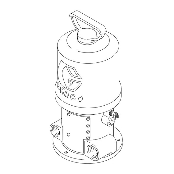
Instructions – Parts List
President
For Water Reducible Fluid Pump
180 psi (1.2 MPa, 12 bar) Maximum Working Pressure
Part No. 210007, Series F
For STANCHION TUBE mounting
Important Safety instructions
Read all warnings and instructions in this manual.
Save these instructions.
GRACO INC. P.O. BOX 1441 MINNEAPOLIS, MN 55440-1441
Copyright 1974, Graco Inc. is registered to I.S. EN ISO 9001
R
Air Motor
307157 rev.L
06714
Advertisement

Related Manuals for Graco President 210007


Summary of Contents for Graco President 210007
- Page 1 Part No. 210007, Series F For STANCHION TUBE mounting Important Safety instructions Read all warnings and instructions in this manual. Save these instructions. 06714 GRACO INC. P.O. BOX 1441 MINNEAPOLIS, MN 55440-1441 Copyright 1974, Graco Inc. is registered to I.S. EN ISO 9001...
- Page 2 D This equipment is for professional use only. D Read all instruction manuals, tags, and labels before operating the equipment. D Use the equipment only for its intended purpose. If you are not sure, call your Graco distributor. D Do not alter or modify this equipment.
- Page 3 WARNING FIRE AND EXPLOSION HAZARD Improper grounding, poor ventilation, open flames or sparks can cause a hazardous condition and re- sult in a fire or explosion and serious injury. D Ground the equipment and the object being sprayed. Refer to Grounding on page 4. D If there is any static sparking or you feel an electric shock while using this equipment, stop spray- ing/dispensing immediately.
- Page 4 NOTE: Always use Genuine Graco Parts and Acces- sories, available from your Graco distributor. 9. To maintain grounding continuity when flushing or relieving pressure, always hold a metal part of the...
- Page 5 Service Pressure Relief Procedure WARNING WARNING A bleed-type master air valve is required in your system, to reduce the risk of serious injury includ- SKIN INJECTION HAZARD ing injury from moving parts if you are adjusting or Fluid under high pressure can be in- repairing the air motor.
- Page 6 Service Servicing the Air Motor WARNING To reduce the risk of serious injury whenever you are instructed to relieve pressure, always follow the Pressure Relief Procedure on page 5. Relieve the pressure, then disconnect the air hose from the motor. Manually push on the piston rod to move the piston to the top of its stroke.
- Page 7 (34) when the toggle assemblies are in (3.68 mm) the down position. See Fig. 3. Special gauge, Part No. 171818, is available. Contact your Graco distributor. Be sure the toggle assemblies (E)are in the up position 06726 and then reinstall the cylinder (22) and the cap nut (24).
- Page 8 Parts Lips Face Down 18† 17† 28† 13† †16 27† 20† 06725 307157...
- Page 9 NUT, adjusting good visibility. DO NOT cover the air exhaust holes. 18† 160618 LOCKWIRE, transfer valve 160623 ARM, toggle Order the labels directly from Graco, free of charge. Toll Free: 20† 160896 STEM, air valve 1–800–367–4023 162628 ROD, piston 162629...
- Page 10 Mounting Hole Dimensions Layout 15.75” (400.1 mm) 161322 7.25” GASKET (146.1 mm ) DIA Three 0.34” (8.6 mm) Diameter Holes on 2.5” 6.38” (162.1 mm) (64 mm) Bolt Circle 06724 1” 3/4” npt 1” npt (25 mm) Fluid Outlet Fluid Return Radius 4”...
- Page 11 Notes 307157...
- Page 12 With the exception of any special, extended, or limited warranty published by Graco, Graco will, for a period of twelve months from the date of sale, repair or replace any part of the equipment determined by Graco to be defective.