
Related Manuals for LG MH-705A


Summary of Contents for LG MH-705A
- Page 1 MICROWAVE/GRILL OVEN SERVICE MANUAL MODEL : MH-705A CAUTION BEFORE SERVICING THE UNIT, READ THE SAFETY PRECAUTIONS IN THIS MANUAL.
-
Page 2: Safety Precautions
SAFETY PRECAUTIONS This device is to be serviced only by properly qualified service personnel. Consult the service manual for proper service procedures to assure continued safety operation and for precautions to be taken to avoid possible exposure to excessive microwave energy. PRECAUTIONS TO BE OBSERVED BEFORE AND DURING SERVICING TO AVOID POSSIBLE EXPOSURE TO EXCESSIVE MICROWAVE ENERGY... -
Page 3: Table Of Contents
CONTENTS (Page) SAFETY PRECAUTIONS - - - - - - - - - - - - - - - - - - - - - - - - - - - - - - - - - - - - - - - - - - - - - - - - - - - - - - - - - - - - - - - - - - - - - Inside front cover SPECIFICATIONS - - - - - - - - - - - - - - - - - - - - - - - - - - - - - - - - - - - - - - - - - - - - - - - - - - - - - - - - - - - - - - - - - - - - - - - - - - - - - - - - - - - - - - - - - - - - - - - - - - - - - 1-1 CAUTIONS - - - - - - - - - - - - - - - - - - - - - - - - - - - - - - - - - - - - - - - - - - - - - - - - - - - - - - - - - - - - - - - - - - - - - - - - - - - - - - - - - - - - - - - - - - - - - - - - - - - - - - - - - - - - - - 2-1 INSTALLATIONS - - - - - - - - - - - - - - - - - - - - - - - - - - - - - - - - - - - - - - - - - - - - - - - - - - - - - - - - - - - - - - - - - - - - - - - - - - - - - - - - - - - - - - - - - - - - - - - - - - - - - - 3-1... -
Page 4: Specifications
SPECIFICATIONS ITEM DESCRIPTION MODEL MH-705A Power Requirement 230 Volts AC 50 Hz Single phase, 3 wire grounded Microwave 1,350W Grill 1,250W Combination 2,550W Power Output 900 Watts full microwave power (IEC705) Microwave Frequency 2,450 MHz Magnetron 2M214 - 39F Timer 90 min. -
Page 5: Cautions
CAUTIONS Unlike other appliances, the microwave oven is MICROWAVE RADIATION high-voltage and high-current equipment. Personnel should not be exposed to the Though it is free from danger in ordinary use, microwave energy which may radiate from the extreme care should be taken during repair. magnetron or other microwave generating device if it is improperly used or connection. -
Page 6: Installations
INSTALLATIONS BEFORE YOU BEGIN, READ THE FOLLOWING INSTRUCTIONS COMPLETELY AND CAREFULLY. INSTALLING EARTHING INSTRUCTIONS 1. Empty the microwave oven and clean inside it with This microwave oven is designed to be used in a fully a soft, damp cloth. Check for damage such as earthed condition. -
Page 7: Operating Instructions
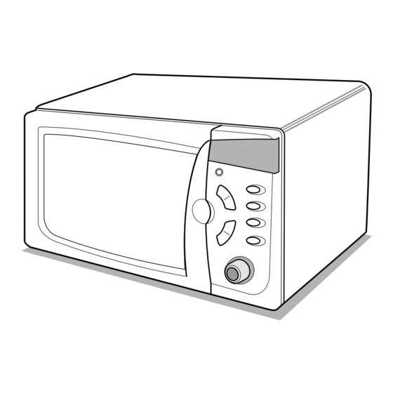
OPERATING INSTRUCTIONS FEATURES Oven Front Plate Window Door Screen Door Seal Display Window Control Panel Safety Door Lock System Grill Rack Glass Tray Rotating Ring CONTROL PANEL 1. INDICATORS 2. SET CLOCK: Used to set the time of day. 3. POWER: Used to select the desired power level for cooking. -
Page 8: Operating Sequence
Operating Sequence The following is a description of component functions 6. AUTO WEIGHT DEFROST during oven operation. Desired Food Stop/Clear defrost Start weight 1. SETTING THE CLOCK category 7. AUTO COOK Desired Stop/Clear Clock hour Desired Food Stop/Clear auto cook Start weight category... -
Page 9: Schematic Diagram
SCHEMATIC DIAGRAM... -
Page 10: Circuit Description
CIRCUIT DESCRIPTION power of microwave oven as POWER LEVEL. GENERAL DETAILS (refer to page 1-1) • The low voltage transformer supplies the necessary voltage to the micom controller when power cord is WHEN THE DOOR IS OPENED DURING plugged in. COOKING •... - Page 11 MICROWAVE/GRILL OVEN SERVICE MANUAL MODEL : MH-705A CAUTION BEFORE SERVICING THE UNIT, READ THE SAFETY PRECAUTIONS IN THIS MANUAL.
-
Page 12: Service Information
SERVICE INFORMATION TOOLS AND MEASURING INSTRUMENTS NECESSARY TOOLS NECESSARY MEASURING INSTRUMENTS Tools normally used for TV servicing are sufficient. • TESTER(VOLTS-DC, AC., Ohmmeter) Standard tools are listed below. • Microwave survey meter • Diagonal pliers - Holaday HI-1500 • Long nose pliers HI-1501 •... - Page 13 MEASUREMENT WITH OUTER CASE NOTES WHEN MEASURING REMOVED • Do not exceed meter full scale deflection. • The test probe must be removed no faster than • When you replace the magnetron, measure for 1 inch/sec (2.5 cm/sec) along the shaded area, microwave energy leakage before the outer case is otherwise a false reading may result.
-
Page 14: Measurement Of Microwave Power Output
MEASUREMENT OF MICROWAVE POWER OUTPUT • Microwave power output measurement is made with • The microwave power output P in watts is calculated the microwave oven supplied at its rated voltage and from the following formula : operated at its maximum microwave power setting with 4187 X (∆T) + 0.88 X (T ) X M a load of (1000±5) g of potable water. - Page 15 D. DOOR GROSS ASSEMBLY REMOVAL E. HIGH VOLTAGE TRANSFORMER 1) Open the door. REMOVAL 2) Remove the choke cover cap very carefully with a 1) Discharge the high voltage capacitor. flat-blade screwdriver. 2) Disconnect the leadwire from magnetron, high voltage CAUTION : Be careful not to damage door seal plate transformer, and capacitor.
- Page 16 H. AIR DUCT ASSEMBLY REMOVAL J. REMOVING THE TURNTABLE MOTOR 1) Remove the turntable. 1) Disconnect the leadwire from lamp and MGT 2) Remove the turntable shaft VERY CAREFULLY thermostat. with a slotted screwdriver. 2) Remove the mounting screw to the magnetron. 3) Lay the unit down on its back.
- Page 17 K. PCB ASSEMBLY REMOVAL 1) Remove the control panel assembly from the L. INTERLOCK SYSTEM cavity. (Refer to control panel assembly removal 1) INTERLOCK MECHANISM on previous page.) The door lock mechanism is a device which has 2) Remove screws which hold the PCB SUB ASS’Y to been specially designed to eliminate completely the control panel.
-
Page 18: Interlock Continuity Test
INTERLOCK CONTINUITY TEST WARNING : FOR CONTINUED PROTECTION AGAINST EXCESSIVE RADIATION EMISSION, REPLACE ONLY WITH IDENTICAL REPLACEMENT PARTS. TYPE NO. SZM-V 16-FA-63 OR VP-533A-OF FOR PRIMARY SWITCH TYPE NO. SZM-V 16-FA-62 OR VP-532A-OF FOR MONITOR SWITCH TYPE NO. SZM-V 16-FA-63 OR VP-533A-OF FOR SECONDARY SWITCH B. -
Page 19: Component Test Procedure
COMPONENT TEST PROCEDURE CAUTIONS 1. DISCONNECT THE POWER SUPPLY CORD FROM THE OUTLET WHENEVER REMOVING THE OUTER CASE FROM THE UNIT. PROCEED WITH THE TEST ONLY AFTER DISCHARGING THE HIGH VOLTAGE CAPACITOR AND REMOVING THE WIRE LEADS FROM THE PRIMARY WINDING OF THE HIGH VOLTAGE TRANSFORMER. - Page 20 COMPONENTS TEST PROCEDURE RESULTS Antenna Gasket Chassis Filament NOTE: When testing the magnetron, be sure to install the magnetron gasket in the correct position and be sure that the gasket is in good condition. HIGH VOLTAGE Measure the resistance. Normal: Momentarily indicates CAPACITOR (Ohm-meter scale: Rx1000) several ohms, and then...
- Page 21 COMPONENTS TEST PROCEDURE RESULTS FUSE Check for continuity of the fuse with an Normal Abnormal multi-meter. NOTE: If the fuse is blown, check the primary, the secondary, and the monitor switches, H.V.D. and H.V.C. before replacing the fuse. If the fuse is blown by improper switch operation replace the defective switch and the fuse at the same time.
- Page 22 COMPONENTS TEST PROCEDURE RESULTS Disconnect the 8 pin Cooking Start connector from P.C.B. (Refer to schemetic diagram on page 4-3) Cooking Start Relay 3 RELAY 2, RELAY 3 OF P.C.B. (Wire leads removed.) Note: Relay Relay 1: Fan motor Turntable motor Oven lamp Relay 2: Microwave Relay 2...
-
Page 23: Trouble Shooting
TROUBLE SHOOTING WHEN YOU GET A COMPLAINT FROM YOUR CUSTOMER, EVALUATE THE COMPLAINT CAREFULLY. IF THE FOLLOWING SYMPTOMS APPLY, PLEASE INSTRUCT THE CUSTOMER IN THE PROPER USE OF THE MICROWAVE OVEN. THIS CAN ELIMINATE AN UNNECESSARY SERVICE CALL. CAUTIONS 1. Check grounding before checking for trouble. 2. - Page 24 (TROUBLE 1) The following visual conditions indicate a probable defective control circuit. 1. Incomplete segments. • Segment missing. • Partial segment missing. • Digit flickering (NOTE: Slight flickering is normal.) 2. Colon does not turn on or blink. 3. A distinct change in the brightness of one or more numbers in display. 4.
- Page 25 (TROUBLE 2) Oven does not operate at all ; Display window does not display any figures and no input is accepted. CONDITION CHECK RESULT CAUSE REMEDY Replace primary Malfunction of the Check continuity 1. Fuse blows. Continuity. and monitor monitor switch. of monitor switches.
- Page 26 (TROUBLE 3) Display shows all figures set, but oven does not start cooking while desired program times are set and START pad is touched. CONDITION CHECK RESULT CAUSE REMEDY Defective Replace Check continuity 1.Setting time does No continuity. secondary switch. secondary switch.
- Page 27 (TROUBLE 5) No microwave oscillation even though oven lamp and fan motor run (Display operates properly) CONDITION CHECK RESULT CAUSE REMEDY No microwave Disconnect the Defective P.C.B Replace P.C.B No continuity. oscillation. wire leads from assembly assembly relay 2 and check continuity Continuity.
- Page 28 (TROUBLE 6) Oven does not cook properly when programmed for the set power level (Operates properly on HIGH) CONDITION CHECK RESULT CAUSE REMEDY Output is full when Defective P.C.B. Replace P.C.B. Disconnect the Abnormal. you set lower assembly. assembly. wire leads from power level.
-
Page 29: Exploded View
EXPLODED VIEW INTRODUCTION OVEN CAVITY PARTS INTERIOR PARTS BASE PLATE PARTS DOOR PARTS LATCH BOARD PARTS CONTROL PANEL PARTS... - Page 30 DOOR PARTS 13581A 15006A 13536A 13552A 13213A 14890A 14026A 14970A 13720D 13806D...
- Page 31 CONTROL PANEL PARTS 24781S 268711 268712 250202 23572A WTP018 250201 23790D 249401 250204 250203...
- Page 32 OVEN CAVITY PARTS WTT021 33112U WTT021 35264A 348102 35301A 33550H WMT002 35300A 348101 33052M WTT010 35026G WSZ092 33390G 34960A 34370T 34036W 35889A 36549S WTP013...
- Page 33 LATCH BOARD PARTS WSZ085 466001 43501A 43500A 466003 44510A 466001...
- Page 34 INTERIOR PARTS 568771 WSZ062 948502 56411A 56930V WSZ112 56930G 54826A 50FZZA WTT028 56201A 56549F 54974S WSZ002 55900A WTT037 WTP004 56930M 56851D 56912B WSZ002 WSZ002 50CZZH 56851C 55262A WTT028 54810C 56324A WSZ002 56201B...
- Page 35 BASE PLATE PARTS 56170D 63302A 63303A 948503 WTT021 647781 WTT030 WSZ002 WSZ062...
-
Page 36: Schematic Diagram Of P.c.b
SCHEMATIC DIAGRAM OF P.C.B... -
Page 37: Printed Circuit Board
PRINTED CIRCUIT BOARD...