Viessmann Vitocrossal 200 CM2 500 Service Instructions Manual
Gas condensing boiler with cylinder burner
Hide thumbs
Also See for Vitocrossal 200 CM2 500:
- Service instructions manual (72 pages) ,
- Installation instructions manual (36 pages) ,
- Operating instructions manual (12 pages)
Table of Contents
Advertisement
Quick Links
Service Instructions
for use by heating contractor
Vitocrossal 200
CM2 Series 400, 500 and 620
Gas condensing boiler with cylinder burner
Heating input:
1445 to 2245 MBH
(423 to 658 kW)
VITOCROSSAL 200
H
5546 489 - 15
05/2021
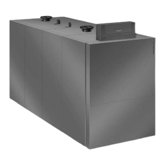
Product may not be exactly as shown
IMPORTANT
Read and save these instructions
for future reference.
Please file in Service Binder
Advertisement
Table of Contents

Related Manuals for Viessmann Vitocrossal 200 CM2 500


Summary of Contents for Viessmann Vitocrossal 200 CM2 500
- Page 1 Service Instructions for use by heating contractor Vitocrossal 200 CM2 Series 400, 500 and 620 Gas condensing boiler with cylinder burner Heating input: 1445 to 2245 MBH (423 to 658 kW) VITOCROSSAL 200 Product may not be exactly as shown IMPORTANT Read and save these instructions for future reference.
-
Page 2: Safety, Installation And Warranty Requirements
Follow the ultimate owner with all equipment, as well as safety Viessmann maintenance schedule of the boiler contained precautions/requirements, shutdown procedure, and in this manual. the need for professional service annually before the... -
Page 3: Safety
Safety Vitocrossal 200, CM2 400, 500 and 620 Service Safety, Installation and Warranty Requirements (continued) Suppliers of fiberglass wool products recommend the Fiberglass wool and ceramic fiber materials following precautions be taken when handling these materials: WARNING - Avoid breathing fiberglass dust and contact with Inhaling of fiberglass wool and/or ceramic fiber skin and eyes. -
Page 4: Table Of Contents
Table of Contents Vitocrossal 200, CM2 400, 500 and 620 Service Page Safety Safety, Installation and Warranty Requirements....2 About these Installation Instructions......3 General Information Equipment..............6 Product Information.............6 Important Regulatory and Installation Requirements..7 Safety Instructions............8 Target group............8 Regulations.............8 If you smell gas............8 If you smell flue gas..........8 Working on the system..........8 Repair work............8... - Page 5 Table of Contents Vitocrossal 200, CM2 400, 500 and 620 Service Page Burner Service Further Details Regarding the Individual Steps....31 Fan pressure monitoring function (air pressure switch 1) ..........31 Combustion chamber pressure monitoring (air pressure switch 2) .........31 Gas inlet pressure monitoring switch - GDW1...32 Valve seat gas pressure monitoring switch - GDW2...32 Auxiliary low gas pressure switch.......34 Burner Component Overview........35...
-
Page 6: General Information
This boiler does not require a flow switch. The Vitocrossal 200, CM2 boilers are CSA certified with WARNING Viessmann burners which must be used in conjunction with this boiler series. Exposing the boiler to pressures and temperatures in The proper burner size must be verified and the burner... -
Page 7: Important Regulatory And Installation Requirements
L eave all literature at the installation site and advise the Literature applicable to all aspects of the Vitocrossal 200, system operator/ultimate owner where the literature CM2: can be found. Contact Viessmann for additional copies. Technical Data Manual Installation Instructions Service Instructions... -
Page 8: Safety Instructions
■ Notify your gas or electricity supply utility from outside the building. VIESSMANN IS NOT RESPONSIBLE FOR ANY DAMAGES ■ Shut off the electricity supply to the building from a THAT THE FOLLOWING TEST PROCEDURE MAY RESULT safe place (outside the building). -
Page 9: Start-Up
Start-up Vitocrossal 200, CM2 400, 500 and 620 Service Safety Instructions (continued) 7. Once the temperature reached the fixed high limit setting, burner control will have a hard lock out with F F2 fault displayed. Burner fan stays on for 10 min. The fault can only be manually reset once the water temperature in the boiler drops. -
Page 10: Removing Covers
Start-up Vitocrossal 200, CM2 400, 500 and 620 Service Removing Covers Removing the front covers 1. Remove the M5 screw and set aside. 2. Lift and remove the top front panel. 3. Lift and remove the lower front panel. Removing the side covers 1. -
Page 11: Burner Overview
Start-up Vitocrossal 200, CM2 400, 500 and 620 Service Burner Overview CM2-400 burner Legend A Compensating tube CM2-500 burner Legend A Compensating tube CM2-620 burner Legend A Compensating tube Model CM2 30 o 20 o Rotary damper position degrees Compensation tubing connection Venturi mixing tube Adaptor plate Adaptor plate... -
Page 12: Commissioning, Inspection And Maintenance
Commissioning, Inspection, Maintenance Vitocrossal 200, CM2 400, 500 and 620 Service Steps – Commissioning, Inspection and Maintenance Commissioning the system 6. Match the coding card at the burner control unit WARNING according to the chart on this page. Also refer to page 55. -
Page 13: Conversion To Liquid Propane Gas (Lpg)
Commissioning, Inspection, Maintenance Vitocrossal 200, CM2 400, 500 and 620 Service Steps – Commissioning, Inspection and Maintenance (continued) Conversion to liquid propane gas (LPG) (The LPG conversion kit is supplied with the burner) 1. Close the gas shut-off valve. 2. Switch OFF the system ON/OFF switch at the boiler control unit. -
Page 14: Conversion To Natural Gas (Ng)
Commissioning, Inspection, Maintenance Vitocrossal 200, CM2 400, 500 and 620 Service Steps – Commissioning, Inspection and Maintenance (continued) Conversion to natural gas (NG) 11.Push compensation hose G on to the gas valve. 1. Close the gas shut-off valve. 12. Apply: 2. -
Page 15: Converting Gas Type On Burner Control Unit
Commissioning, Inspection, Maintenance Vitocrossal 200, CM2 400, 500 and 620 Service Steps – Commissioning, Inspection and Maintenance (continued) Converting gas type on burner control unit Altitude adjustment To implement the changes the burner has to be in To implement the changes the burner has to be in stand-by, Status “0”, Service “C”. -
Page 16: Reducing Operational Input (If Required)
Commissioning, Inspection, Maintenance Vitocrossal 200, CM2 400, 500 and 620 Service Steps – Commissioning, Inspection and Maintenance (continued) Checking the static and the supply pressure Reducing operational input (if required) To implement the changes the burner has to be in stand-by, Status “0”, Service “C”. -
Page 17: Supply Pressure For Ng And Lpg
Commissioning, Inspection, Maintenance Vitocrossal 200, CM2 400, 500 and 620 Service Steps – Commissioning, Inspection and Maintenance (continued) Supply pressure for NG and LPG. 1. Start the burner Note: The supply pressure should be between 4“w.c. and 14”w.c. The gas pressure switch for the inlet Note: For commissioning, see page 12. -
Page 18: Checking The Co Level
Commissioning, Inspection, Maintenance Vitocrossal 200, CM2 400, 500 and 620 Service Steps – Commissioning, Inspection and Maintenance (continued) Checking the CO level Test at the upper heating input Preparing the test 1. Press button E until the service display B has incremented to “100“(= 100%). -
Page 19: Co Test At The Lower Heating Output
Commissioning, Inspection, Maintenance Vitocrossal 200, CM2 400, 500 and 620 Service Steps – Commissioning, Inspection and Maintenance (continued) Displaying the ionization current Test at the lower heating output 1. Press button G until the service display B has counted down to “0“ (lower heating output). 2. -
Page 20: Shutting Down The System
Commissioning, Inspection, Maintenance Vitocrossal 200, CM2 400, 500 and 620 Service Steps – Commissioning, Inspection and Maintenance (continued) Shutting down the system 1. Close the gas shut-off valve. 2. Switch OFF the main circuit breaker or the power supply and safeguard against unauthorized reconnection. WARNING Mains voltage can be extremely dangerous. -
Page 21: Separating The Neutralizing System (If Installed) From The Boiler And Connecting The Drain Hose
Commissioning, Inspection, Maintenance Vitocrossal 200, CM2 400, 500 and 620 Service Steps – Commissioning, Inspection and Maintenance (continued) Separating the neutralizing system (if installed) from the boiler and connecting the drain hose 1. Separate hose A to the neutralizing system from siphon B. -
Page 22: Cleaning And Reconnecting The Condensate Drain System
See Neutralization System Operating Instructions. Note: You can obtain the neutralizing granulate from Viessmann. 4. Release and flush lower part D of siphon B. 5. Fill lower part D of siphon B with water and reassemble. -
Page 23: Checking The Cylinder Burner Assembly
Commissioning, Inspection, Maintenance Vitocrossal 200, CM2 400, 500 and 620 Service Steps – Commissioning, Inspection and Maintenance (continued) Checking the cylinder burner assembly WARNING Escaping gas leads to a risk of explosion. Close the gas shut-off valve. 1. Undo fitting on the gas supply pipe A. 2. -
Page 24: Checking The Ignition And Ionization Electrodes
Commissioning, Inspection, Maintenance Vitocrossal 200, CM2 400, 500 and 620 Service Steps – Commissioning, Inspection and Maintenance (continued) Checking the ignition and ionization electrodes Ionization electrode Check the ignition electrodes and the ionization electrode for correct gap towards the cylinder burner assembly and damage (replace if required). -
Page 25: Checking The 15A And 15B Flue Gas Sensor
Steps – Commissioning, Inspection and Maintenance (continued) Checking the 15A and 15B flue gas sensor Viessmann NTC 10 kΩ (blue identification) Note: The sensor is located on the flue gas collector and the connecting plug is located at the burner control unit. -
Page 26: 3A And 3B Boiler Temperature Sensor Description
Commissioning, Inspection, Maintenance Vitocrossal 200, CM2 400, 500 and 620 Service Steps – Commissioning, Inspection and Maintenance (continued) 3A and 3B boiler temperature sensor description 3A sensor (NTC 10k ) terminals 1 & 2 3B sensor (NTC 20k ) terminals 3 & 4... -
Page 27: Making The Electrical Burner Connection
Commissioning, Inspection, Maintenance Vitocrossal 200, CM2 400, 500 and 620 Service Steps – Commissioning, Inspection and Maintenance (continued) Making the electrical burner connection Note: Never allow cables/leads to come into contact with hot components. Secure all cables with cable ties if required. -
Page 28: Cleaning The Burner
Commissioning, Inspection, Maintenance Vitocrossal 200, CM2 400, 500 and 620 Service Steps – Commissioning, Inspection and Maintenance (continued) Cleaning the burner 1. Undo fitting C on gas supply pipe B. 2. Undo Venturi mixing pipe D from fan E. 3. Remove Venturi mixing pipe D with gas valve A and gas supply pipe B, and pull out connecting cables. -
Page 29: Checking All Gas Connections For Leaks
Commissioning, Inspection, Maintenance Vitocrossal 200, CM2 400, 500 and 620 Service Steps – Commissioning, Inspection and Maintenance Checking all gas connections for leaks The burner control unit automatically checks the valves for tightness when the burner is started. If the valves are gas tight, the burner enters standard mode and the burner starts. -
Page 30: Checking The Diaphragm Expansion Vessel And System Pressure
If in any doubt about the water quality, please have a be properly sized for the system. proper water analysis done. Check with regional chemical suppliers for boiler water treatment or with Viessmann Manufacturing Company Inc. directly. CAUTION Total output (MBH) Total Hardness (ppm as CaCO Damage on boiler or other system components may >... -
Page 31: Further Details Regarding The Individual Steps
Burner Service Vitocrossal 200, CM2 400, 500 and 620 Service Further Details Regarding the Individual Steps Fan pressure monitoring function (air pressure switch 1) Combustion chamber pressure monitoring (air pressure switch 2) The switching threshold of air pressure switch 1 (APS1) To monitor the combustion chamber pressure, the is monitored in all fan ramp-up phases and checked in switching threshold of air pressure switch 2 (APS2) -
Page 32: Gas Inlet Pressure Monitoring Switch - Gdw1
Burner Service Vitocrossal 200, CM2 400, 500 and 620 Service Further Details Regarding the Individual Steps (continued) Gas inlet pressure monitoring switch - GDW1 The factory default setting for the gas inlet pressure switch is 10 mbar (4” w.c.). This is the minimum gas pressure required for the burner to operate with natural gas fuel. - Page 33 Burner Service Vitocrossal 200, CM2 400, 500 and 620 Service Further Details Regarding the Individual Steps (continued) Gas inlet pressure monitoring switch - GDW1 Combustion chamber pressure monitoring (air pressure switch 2) The factory default setting for the gas inlet pressure switch is 10 mbar (4”...
-
Page 34: Auxiliary Low Gas Pressure Switch
Burner Service Vitocrossal 200, CM2 400, 500 and 620 Service Auxiliary Low Gas Pressure Switch Installation steps 1. Disconnect boiler power supply. 2. If the boiler has already been installed, shut off main gas supply to the boiler and disconnect gas supply piping. -
Page 35: Burner Component Overview
Burner Service Vitocrossal 200, CM2 400, 500 and 620 Service Burner Component Overview CM2 pre-mix cylinder burner 400/500/620 Legend A Burner frame J Manual shut-off valve B Air pressure switch 1 K Venturi mixing pipe C Air pressure switch 2 L Gas fan D Display and programming unit M Burner gauze assembly... -
Page 36: Accessing The Burner
Burner Service Vitocrossal 200, CM2 400, 500 and 620 Service Accessing the Burner 1. Close main gas supply valve. 2. Switch off main power switch. Ensure that main power to equipment being serviced is off. 3. Remove front panel and front side panels. Refer to the boiler Installation Instructions. -
Page 37: Burner Control Coding Card
Burner Service Vitocrossal 200, CM2 400, 500 and 620 Service Burner Control (continued) 4. Remove coding card from burner control sub-base and set aside. Note: Ensure there is no power to the burner control when replacing the coding card. 5. Loosen the four screws from the burner control sub-base. -
Page 38: Burner Control Programming Unit
Burner Service Vitocrossal 200, CM2 400, 500 and 620 Service Burner Control Programming Unit 1. Loosen the two programming unit screws. 2. Lift the programming unit off the burner control sub-base and disconnect the cable plug and replace. 3. Reinstall in reverse order. Gas Valve 1. -
Page 39: Ignition Unit
Burner Service Vitocrossal 200, CM2 400, 500 and 620 Service Ignition Unit 1. Remove plug from ignition unit. 2. Remove ignition cables from ignition unit. 3. Loosen screws of ignition unit. 4. Remove ignition unit. 5. Reinstall in reverse order. Ignition Cable 1. -
Page 40: Motorized Burner Inlet Damper
Burner Service Vitocrossal 200, CM2 400, 500 and 620 Service Motorized Burner Inlet Damper 1. Remove the four M6 (5 mm hex) bolts and nuts from the burner inlet damper and set aside. 2. Remove the burner inlet damper from the burner along with the servomotor and linkage. -
Page 41: Inlet Damper Linkage
Burner Service Vitocrossal 200, CM2 400, 500 and 620 Service Inlet Damper Linkage 1. Remove the M4 (8 mm hex) nut connecting the linkage to the inlet damper bracket. 2. Loosen the M5 (4 mm hex key) set screw connecting the linkage to the servomotor. -
Page 42: Burner Fan
Burner Service Vitocrossal 200, CM2 400, 500 and 620 Service Burner Fan 1. Loosen the retaining clamp and disconnect the combustion air flex hose and set aside. 2. Disconnect the gas line. 3. Disconnect electrical plugs 100 and 100A from the fan. 4. - Page 43 Burner Service Vitocrossal 200, CM2 400, 500 and 620 Service Burner Tube (continued) The electrodes 1. Disconnect both the ignition and ionization plugs from the electrodes and remove the nuts, retaining brackets and electrodes and set aside. 2. Once the burner is installed to the burner door (see page 39), install the electrodes in reverse order.
-
Page 44: Burner Door
Burner Service Vitocrossal 200, CM2 400, 500 and 620 Service Burner Tube (continued) The burner 1. Install the burner with frame to the boiler door with six M12 nuts and washers. Torque nuts to 177 lb.in (20 Nm). 2. Remove the six M12 bolts and washers and set aside. Open the boiler door and remove the plastic sleeve on the burner tube and check the electrode gaps (see electrodes on page 24). - Page 45 Burner Service Vitocrossal 200, CM2 400, 500 and 620 Service Burner Door (continued) 7. Disconnect electrical plugs 100 and 100A from the fan. Disconnect pressure switch tubes APS1 from the venturi and APS2 from the burner door. Remove the four M8 (13 mm hex) nuts connecting the fan to the burner door and set aside.
-
Page 46: Burner Door Refractory
Burner Service Vitocrossal 200, CM2 400, 500 and 620 Service Burner Door Refractory 1. Loosen the retaining clamp and disconnect the combustion air flex hose and set aside. 2. Disconnect the gas line. 3. Remove ionization electrode block. 4. Remove ignition electrode block. 5. -
Page 47: Further Installation And Initial Start Up Instructions
Boiler Service Vitocrossal 200, CM2 400, 500 and 620 Service Further Installation and Initial Start Up Instructions CAUTION Using leak detection spray may lead to a malfunction. Avoid contact between leak detection spray and electric contacts. 1. Ensure all connections are tight and all electrical plugs are connected. -
Page 48: Flue Gas Temperature Sensor
Burner Service Vitocrossal 200, CM2 400, 500 and 620 Service Flue Gas Temperature Sensor For Boilers Equipped with Individual Temperature Sensors Note: The flue gas temperature sensor is located on the flue gas collector. 1. Remove the screws, the cable strap and connector cover from the flue gas collector and set aside. -
Page 49: Burner Control Unit
Burner Control Unit Vitocrossal 200, CM2 400, 500 and 620 Service Burner Control Unit Display and programming unit Standby A display and programming unit is integrated into the burner control unit. The display indicates the relevant operating conditions, the service and parameter conditions as well as all fault and error messages. - Page 50 Burner Control Unit Vitocrossal 200, CM2 400, 500 and 620 Service Burner Control Unit (continued) Operating display (continued) Maintenance program Pre-ignition no air pressure Ignition Maintenance program Safety time no gas pressure or Flame established mains under voltage Flame stabilization Forced ventilation when no flame was recognized...
-
Page 51: Information And Configuration Display
Burner Control Unit Vitocrossal 200, CM2 400, 500 and 620 Service Burner Control Unit (continued) Information and configuration display The information display and the configuration display are Example: to delete the hours run meter, press the activated from the operating display. The menu selection following buttons: is activated by pressing button S for longer than 2 seconds. - Page 52 Burner Control Unit Vitocrossal 200, CM2 400, 500 and 620 Service Burner Control Unit (continued) Configurations: Menu item Description Changeover from the operating display of the burner control unit phase to other process information Configuration of control function operating parameters Menu item “5“...
-
Page 53: Resetting Operating Parameters To Their Factory Settings
Burner Control Unit Vitocrossal 200, CM2 400, 500 and 620 Service Burner Control Unit (continued) Example: to set the maximum operational burner input Example: to set the motorized flue damper (flue gas to between 0 and 100%, press the following buttons: cascade) press the following buttons: 1. -
Page 54: Burner Control Unit Flow Diagram
Flow Diagram Vitocrossal 200, CM2 400, 500 and 620 Service Burner Control Unit Flow Diagram... - Page 55 Flow Diagram Vitocrossal 200, CM2 400, 500 and 620 Service Burner Control Unit Flow Diagram (continued) State description: Phase Display Description Duration System start “A” System start 10 seconds Fan ramp-up, system start max. 20 seconds Forced ventilation, system start 20 seconds Relay test ”P“...
-
Page 56: Burner Control Unit Connection Diagram
Connection Diagram Vitocrossal 200, CM2 400, 500 and 620 Service Burner Control Unit Connection Diagram WARNING Disconnect power inside the boiler junction box, before CAUTION servicing boiler. Provide disconnect means and overload protection as A Burner control unit interface VUC 310/base required. -
Page 57: Faults
Troubleshooting Vitocrossal 200, CM2 400, 500 and 620 Service Faults Fault display Fault memory The fault display is activated automatically if the burner The ten most recent faults are saved and may be called control unit switches to a fault state. The most recent up. -
Page 58: Fault Codes
Troubleshooting Vitocrossal 200, CM2 400, 500 and 620 Service Fault Codes General process errors Fault display on the display interface and programming unit on the burner. Note: Carry out measures in the described order. All fault codes are saved to the fault memory and the last 10 can be called up. - Page 59 Troubleshooting Vitocrossal 200, CM2 400, 500 and 620 Service Fault Codes (continued) Displayed System Characteristics Cause Measures Fault Code F EE Burner control unit in a fault Internal error in feedback from Reset burner control unit; replace state gas safety valves; output relay burner control unit does not respond F EF...
- Page 60 Troubleshooting Vitocrossal 200, CM2 400, 500 and 620 Service Fault Codes (continued) Displayed System Characteristics Cause Measures Fault Code F F4 No flame builds during safety Combustion characteristics not Adjust the burner (see from page time; ionization flame monitor ideal 15, if necessary, also adjust the reports no signal setting screws when the burner is...
-
Page 61: Internal System Fault
Troubleshooting Vitocrossal 200, CM2 400, 500 and 620 Service Fault Codes (continued) Internal system fault Internal system faults are created if a perfect program sequence can no longer be guaranteed. Displayed Fault Code System Characteristics Cause Measures F E5, F EC, F ED, F Fault around burner Internal system fault and Reset burner control unit. -
Page 62: Installation Fittings
Please provide Model and Serial Number from the ASME rating plate B when ordering replacement parts. Order replacement components from your Viessmann distributor. 0401 Pressure relief valve, 75 psi 0402 Nipple 1 in. x 2 in. 0403 90° Street elbow 1 in. -
Page 63: Parts Lists
Boiler 7513668 Ordering Replacement Parts: Please provide Model and Serial Number from the ASME rating plate B when ordering replacement parts. Order replacement components from your Viessmann distributor. Parts for Boiler Assembly 0001 Flue gas collector with gasket (see page 64) - Page 64 Boiler 7513668 Ordering Replacement Parts: Please provide Model and Serial Number from the ASME rating plate when ordering replacement parts. Order replacement components from your Viessmann distributor. Parts for Flue Gas Collector Assembly - 2 x single-flue gas sensor version...
- Page 65 Boiler 7513668 Ordering Replacement Parts: Please provide Model and Serial Number from ASME rating plate when ordering replacement parts. Order replacement components from your Viessmann distributor. Parts for Insulation Assembly 0001 Side panel, front left 0002 Side panel, front right...
- Page 66 Burner 7542297 Ordering Replacement Parts: Please provide Model and Serial Number from ASME rating plate when ordering replacement parts. Order replacement components from your Viessmann distributor. Parts for Burner Assembly 0001 Burner chassis 0002 Accessory pack (burner parts) 0003 Burner tube with gasket...
- Page 67 Ordering Replacement Parts: Please provide Model and Serial Number from ASME rating plate when ordering replacement parts. Order replacement components from your Viessmann distributor. Parts for Electrical Box Assembly 0001 Electrical box without harnesses * 0002 Accessory pack (sensors, harnesses) *...
- Page 68 Specifications Vitocrossal 200, CM2 400, 500 and 620 Service Technical Data Boiler Model 1445 1800 2245 Input (kW) (423) (527) (658) Minimum Input NG (kW) (84) (105) (132) Minimum Input LPG (kW) (103) (129) (160) Output* 1372 1710 2132 (kW) (402) (501) (625)
-
Page 69: Technical Data
Specifications Vitocrossal 200, CM2 400, 500 and 620 Service Technical Data (continued) Boiler Model Boiler Water Content (395) (425) (495) Heat exchanger surface 166.6 208.6 water cooled (15.5) (19.4) (21.7) Maximum Operating Temperature °F (°C) 210 (99) 210 (99) 210 (99) °F (°C) 95 (203) 95 (203) -
Page 70: Cylinder Burner
Specifications Vitocrossal 200, CM2 400, 500 and 620 Service Cylinder Burner Specifications Boiler Model CM2 Voltage Frequency Power consumption NG at max. input at min. input Power consumption LPG at max. input at min. input Version modulating Dimensions ¾ Length in. -
Page 71: Maintenance Record
Inspection and Maintenance Vitocrossal 200, CM2 400, 500 and 620 Service Maintenance Record Setting and Test Values Commissioning Maintenance/Service Static Pressure mbar(”w.c.) Supply Pressure (running pressure) mbar(”w.c.) for natural gas NG mbar(”w.c.) . for liquid propane gas LPG Tick gas type Carbon Dioxide Content CO actual % by vol. - Page 72 Inspection and Maintenance Vitocrossal 200, CM2 400, 500 and 620 Service Maintenance Schedule The following is an overview of scheduled service steps. Regular service work ensures reliable, energy-efficient, and environmentally friendly operation. IMPORTANT Keep boiler and boiler room clear and free from combustible materials, gasoline and other flammable vapors and liquids.
-
Page 73: Maintenance Schedule
Inspection and Maintenance Vitocrossal 200, CM2 400, 500 and 620 Service Maintenance Schedule (continued) Frequency Performed by Service Annually Owner / Ensure service work/test is conducted at least annually by qualified personnel, Operator and that any deficiencies are corrected immediately. Heating Test functionality of safety high limits. - Page 74 Vitocrossal 200, CM2 400, 500 and 620 Service...
- Page 75 Vitocrossal 200, CM2 400, 500 and 620 Service...
- Page 76 Vitocrossal 200, CM2 400, 500 and 620 Service...