
Related Manuals for Whirlpool Maytag MVWP576KW


Summary of Contents for Whirlpool Maytag MVWP576KW
- Page 1 M-17 TECHNICAL MANUAL Maytag® 3.5 cu. ft. Commercial-Grade Residential Agitator Washer W11441706...
- Page 2 • Successfully perform necessary repairs. • Successfully return the top load washer to its proper operational status. WHIRLPOOL CORPORATION assumes no responsibility for any repairs made on our products by anyone other than authorized In-Home Service Professionals. ©2020 Whirlpool Corporation. Benton Harbor, MI 49022 Maytag 3.5 cu.ft.
-
Page 3: Table Of Contents
TABLE OF CONTENTS Maytag 3.5 cu. ft. Commercial-Grade Residential Agitator Washer ® SECTION 1: GENERAL INFORMATION ................. 1-1 SAFETY ..............................1-2 GENERAL THEORY OF OPERATION ..................... 1-3 MODEL AND SERIAL NUMBER LABEL LOCATION ................1-5 TECH SHEET LOCATION ........................1-5 MODEL AND SERIAL NUMBER NOMENCLATURE ................ - Page 4 Notes Maytag 3.5 cu.ft. Commercial-Grade Residential Agitator Washer ®...
-
Page 5: Section 1: General Information
GENERAL INFORMATION Section 1: General Information This section provides general safety, parts, and information for the “Maytag® 3.5 cu. ft. Commercial-Grade Residential Agitator Washer.” ■ Safety ■ General Theory of Operation ■ Model and Serial Label Location ■ Tech Sheet Location ■... -
Page 6: Safety
GENERAL INFORMATION (Cont.) Safety Your safety and the safety of others are very important. We have provided many important safety messages in this manual and on your appliance. Always read and obey all safety messages. This is the safety alert symbol. This symbol alerts you to potential hazards that can kill or hurt you and others. -
Page 7: General Theory Of Operation
GENERAL INFORMATION (Cont.) General Theory of Operation Introduction Splutch The Maytag® 3.5 cu. ft. Commercial-Grade Residential Agitator Spring Washer has several familiar features and some new designs integrating them into this totally new design. Drive System Motor Basket Drive Gear Bi-directional PSC (Permanent Split Capacitor) 120 VAC. - Page 8 GENERAL INFORMATION (Cont.) Shifter/Actuator Lid Lock The actuator serves several functions. It has a synchronous motor that shifts the splutch slider and monitors the position of the splutch. It also houses a transmission speed/position optical sensor. A. Shifter/Actuator The shifter motor rotates a cam, attached to the shifter arm which moves between two positions.
-
Page 9: Model And Serial Number Label Location
GENERAL INFORMATION (Cont.) Model and Serial Number Label Location Model and Serial Number plate Tech Sheet Location Tech Sheet Location Maytag 3.5 cu.ft. Commercial-Grade Residential Agitator Washer ®... -
Page 10: Model And Serial Number Nomenclature
GENERAL INFORMATION (Cont.) Model and Serial Number Nomenclature Maytag Top Load Washer Model ® MODEL NUMBER INTERNATIONAL SALES OR MARKETING CHANNEL Brand M = Maytag® Categories VW = Top Load Washer Model P = Professional Feature Pack Ranges from 215–955 (The higher the number the more features available.) Year Model Introduced K = 2020... -
Page 11: Product Specifications
GENERAL INFORMATION (Cont.) Product Specifications Maytag 3.5 cu. ft. Commercial-Grade Residential Agitator Washer ® Dimensions Capacity (DOE) US (cu. ft.) Capacity IEC CAN (cu. ft.) Depth With Door Open 90 Degree (IN, inches) Depth (IN, inches) Door Opening Height (IN, inches) Door Opening Width (IN, inches) Height with Lid Open Maximum Height (IN, inches) - Page 12 GENERAL INFORMATION (Cont.) Product Specifications (Continued) Cycles Number of Wash Cycles Washer Cycle Selections Bulky Items Delicates Drain and Spin Mixed Normal Powerwash® Rinse and Spin Options Number of Washer Options Washer Option Selections Presoak and Extra Rinse Extra Rinse Presoak Modifiers Number of Wash/Rinse Temperatures...
-
Page 13: Product Features
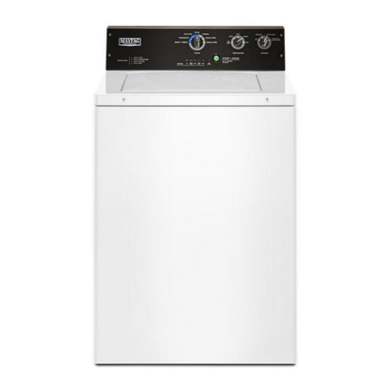
GENERAL INFORMATION (Cont.) Product Features Control Panel 1. Wash Cycle Knob 4. Start/Pause Button Use the Wash Cycle knob to select cycles on your washer. Knob does Press to start the selected cycle. To unlock the lid during Final Spin, press not advance during the progress of the cycle see cycle status lights for to pause the cycle. - Page 14 GENERAL INFORMATION Notes 1-10 Maytag 3.5 cu.ft. Commercial-Grade Residential Agitator Washer ®...
-
Page 15: Section 2: Diagnostics And Troubleshooting
DIAGNOSTICS AND TROUBLESHOOTING Section 2: Diagnostics and Troubleshooting This section provides diagnostic, fault codes, and troubleshooting information for the “Maytag® 3.5 cu. ft. Commercial-Grade Residential Agitator Washer.” ■ Safety ■ Cycle Guide ■ Diagnostic Guide ■ Diagnostic LED – Main Control ■... -
Page 16: Safety
DIAGNOSTICS AND TROUBLESHOOTING (Cont.) For Service Technician Use Only Safety DANGER WARNING Electrical Shock Hazard Electrical Shock Hazard Only authorized technicians should perform Disconnect power before servicing. diagnostic voltage measurements. Replace all parts and panels before operating. After performing voltage measurements, Failure to do so can result in death or disconnect power before servicing. - Page 17 DIAGNOSTICS AND TROUBLESHOOTING (Cont.) For Service Technician Use Only Cycle Guide For best fabric care, choose the cycle that best fits the load being washed. Not all cycles and options are available on all models. Items to wash: Cycle: Wash Spin Cycle Details: Temperature:*...
-
Page 18: Diagnostic Guide
DIAGNOSTICS AND TROUBLESHOOTING (Cont.) For Service Technician Use Only Diagnostic Guide Failure Mode If the incoming water supply is restricted or off, the cycle will end and Before Servicing, check the following: the following three LEDs will be lit. Opening and closing the lid will reset n Make sure there is power at the wall outlet. - Page 19 DIAGNOSTICS AND TROUBLESHOOTING (Cont.) For Service Technician Use Only n Successful activation of Diagnostic Test Modes will be indicated by n Factory Calibration Test Mode all status LEDs (except for LID LOCKED) flashing ON and OFF in half- n Clean Washer Cycle second intervals.
- Page 20 DIAGNOSTICS AND TROUBLESHOOTING (Cont.) For Service Technician Use Only Fault/Error Code Display Method Manual Overview Test Mode Fault/error codes are displayed by alternating the state of the Status To access Manual Overview Test Mode, perform steps 1 and 2 of LEDs in one second intervals.
- Page 21 DIAGNOSTICS AND TROUBLESHOOTING (Cont.) For Service Technician Use Only Drain and Spin Cycle Software Version Display Mode To access the Drain and Spin Cycle, perform steps 1 and 2 of Activating To access Software Version Display Mode, perform steps 1 and 2 the Service Diagnostic Test Modes.
- Page 22 DIAGNOSTICS AND TROUBLESHOOTING (Cont.) For Service Technician Use Only Tachometer Verification Mode Clean Washer Cycle To access Tachometer Verification Mode, perform steps 1 and Puts washer into the Washer Cleanout Cycle. To access the Clean 2 of Activating the Service Diagnostic Modes. Toggle the cycle Washer Cycle, perform steps 1 and 2 of Activating the Service selector knob until the status LEDs correspond as follows: Diagnostic Test Modes.
-
Page 23: Fault/Error Codes
DIAGNOSTICS AND TROUBLESHOOTING (Cont.) For Service Technician Use Only Fault/Error Codes = ON See page to access Fault Code Display Mode. Fault/Error Code – Description Fault Number Error Number Status LEDs Status LEDs Explanation and Recommended Procedure (Status LED names may vary between makes and models) F0E0 –... - Page 24 DIAGNOSTICS AND TROUBLESHOOTING (Cont.) For Service Technician Use Only Fault/Error Code – Description Fault Number Error Number Status LEDs Status LEDs Explanation and Recommended Procedure (Status LED names may vary between makes and models) F5E1 – LID SWITCH FAULT Fault is displayed if lid is in locked state, but lid switch is open. n User presses START with lid open.
- Page 25 DIAGNOSTICS AND TROUBLESHOOTING (Cont.) For Service Technician Use Only Fault/Error Code – Description Fault Number Error Number Status LEDs Status LEDs Explanation and Recommended Procedure (Status LED names may vary between makes and models) F7E7 – MOTOR UNABLE TO REACH TARGET RPM Fault is displayed when basket speed sensor detects that target RPM was not reached.
-
Page 26: Quick Overview Test Mode
DIAGNOSTICS AND TROUBLESHOOTING (Cont.) For Service Technician Use Only Fault/Error Code – Description Fault Number Error Number Status LEDs Status LEDs Explanation and Recommended Procedure (Status LED names may vary between makes and models) F9E1 – LONG DRAIN Fault is displayed when the water level does not change after the drain pump is on for 10 minutes. n Is the drain hose or the drain pump clogged? Check tub sump under impeller for obstructions. -
Page 27: Manual Overview Test Mode
DIAGNOSTICS AND TROUBLESHOOTING (Cont.) For Service Technician Use Only Manual Overview Test Mode Pressing the START button will activate/deactivate each output. When the output is activated, the corresponding Status LEDs will flash. See page access Manual Overview Test Mode. IMPORTANT: Lid must be closed and locked to perform SPIN and AGITATE tests. = ON OUTPUT Status LEDs... -
Page 28: Troubleshooting Guide
DIAGNOSTICS AND TROUBLESHOOTING (Cont.) For Service Technician Use Only OUTPUT Status LEDs Output Details NOTE: Outputs will time-out after 5 minutes. GENTLE AGITATION – To perform test, lid must be closed and locked. Shifts from idle motor to gentle CW/CCW agitation. NOTE: Allow up to 15 seconds for shifter to reposition. - Page 29 DIAGNOSTICS AND TROUBLESHOOTING (Cont.) For Service Technician Use Only Problem Possible Cause Checks and Tests UI WILL NOT ACCEPT User Interface problem. TEST #4: Console and Indicators. SELECTIONS Main control problem. TEST #1: Main Control. WILL NOT FILL 1. Check water connections to washer. No water supplied to washer.
- Page 30 DIAGNOSTICS AND TROUBLESHOOTING For Service Technician Use Only Problem Possible Cause Checks and Tests CYCLE TIME LONGER THAN 1. Verify use of HE detergent. Oversuds. EXPECTED 2. Excessive detergent usage. Off balance. 1. Load is off balance. 2. Balance ring water leak. Weak suspension.
-
Page 31: Section 3:Component Testing
COMPONENT TESTING Section 3: Component Testing This section provides the wiring diagram and component location for the “Maytag® 3.5 cu. ft. Commercial-Grade Residential Agitator Washer.” ■ Safety ■ Wiring Diagram ■ Troubleshooting Tests ■ Component Location Maytag 3.5 cu.ft. Commercial-Grade Residential Agitator Washer ®... -
Page 32: Safety
COMPONENT TESTING (Cont.) For Service Technician Use Only Safety WARNING DANGER Electrical Shock Hazard Electrical Shock Hazard Only authorized technicians should perform Disconnect power before servicing. diagnostic voltage measurements. Replace all parts and panels before operating. After performing voltage measurements, Failure to do so can result in death or disconnect power before servicing. -
Page 33: Wiring Diagram
COMPONENT TESTING (Cont.) For Service Technician Use Only Wiring Diagram IMPORTANT: Electrostatic discharge may cause damage to machine control electronics. See page for ESD information. NOTE: Schematic shows shifter in SPIN position, lock switch open, and motor off. Legend Maytag 3.5 cu.ft. -
Page 34: Troubleshooting Tests
COMPONENT TESTING (Cont.) For Service Technician Use Only Troubleshooting Tests TEST #1: Main Control 7. With a voltmeter set to DC, connect black probe to This test checks for incoming and outgoing supplies to and from the main control. This test assumes that proper voltage is present at the J2-3 (Circuit Gnd) and red probe to J2-4 (+13 VDC). - Page 35 COMPONENT TESTING (Cont.) For Service Technician Use Only 9. Main Control has malfunctioned. Functional Check: a. Unplug washer or disconnect power. 1. Check the shifter and electrical connections by performing both the Spin AND Agitate test under Manual Overview b. Replace the main control. Test Mode.
- Page 36 COMPONENT TESTING (Cont.) For Service Technician Use Only 15. Replace the shifter assembly. SPIN = +5 VDC AGITATE = 0 VDC a. Unplug washer or disconnect power. n If voltage corresponds to setting, go to step 10. b. Replace shifter assembly. n If voltage does not switch, go to step 12.
- Page 37 COMPONENT TESTING (Cont.) For Service Technician Use Only 8. With a voltmeter set to AC, connect black probe to motor n If a steady increase in resistance is noted, continue to step 16. relay pin 2, red probe to J16-7 (CW Winding). n If the capacitor is either shorted or open, replace capacitor, calibrate the washer, and repeat step 1.
- Page 38 COMPONENT TESTING (Cont.) For Service Technician Use Only NOTE: Most thermistor errors are a result of the resistor NOTE: Status LED names may vary between makes and models. Use LED # identification. being out of range. If the temperature thermistor malfunctions, the washer will default to pre-programmed wash settings.
- Page 39 COMPONENT TESTING (Cont.) For Service Technician Use Only TEST #8: Lid Lock 8. Visually check the electrical connections at the drain pump. n If visual check passes, go to step 9. Perform the following checks if the washer does not lock (or unlock). n If connections are loose, reconnect the electrical connections 1.
-
Page 40: Component Location
COMPONENT TESTING (Cont.) For Service Technician Use Only Component Location Console and Valves A. Motor Relay (not present on all models) B. Hot Water Valve C. Temperature Thermistor D. Cold Water Valve E. Pressure Hose F. Main Control Board G. Water Temperature Encoder H. - Page 41 COMPONENT TESTING (Cont.) For Service Technician Use Only Component Location (cont.) Drive System and Drain Pump A. Drive Motor B. Motor Pulley C. Drive Belt D. Shaft Pulley E. Motor Capacitor F. Drain Hose G. Drain Pump H. Shifter Assembly Connector I.
- Page 42 COMPONENT TESTING Notes 3-12 Maytag 3.5 cu.ft. Commercial-Grade Residential Agitator Washer ®...
-
Page 43: Section 4: Component Access
COMPONENT ACCESS Section 4: Component Access This section provides service parts access, removal, and installation instructions for the “Maytag® 3.5 cu. ft. Commercial-Grade Residential Agitator Washer.” n Console Open and Components n Components Accessible under Top Panel n Components Accessible from the Bottom Maytag 3.5 cu.ft. -
Page 44: Console Open And Components
COMPONENT ACCESS (Cont.) Console Open and Components Upper Back Panel Upper Front Panel and Supporting Panels WARNING 6. Complete the steps 1-5 from Upper Back Panel removal instructions. 7. To avoid damage, lay a towel on the washer and place tools or removed parts on towel. - Page 45 COMPONENT ACCESS (Cont.) 11. Components located in the console are the: 4. Disconnect the power connector to the transformer by lifting the locking tab and separating the connector. A. Power Connector B. Transformer 5. Remove the 5/16" (8 mm) hex head screw securing the A.
- Page 46 COMPONENT ACCESS (Cont.) Motor Relay 6. Pull the wire harness connector off the cold water inlet valve. 1. Complete the steps 1-10 from Panels removal instructions. 2. Remove the Power cord. 3. Remove the Water Inlet Valve and Thermistor. 4. Slide the motor relay out from under the screw and remove it from the console.
- Page 47 COMPONENT ACCESS (Cont.) Temperature Selector Switch Central Control Unit Connections 1. Complete the steps steps 1-10 from Panels removal 1. Complete the steps 1-10 from Panels removal instructions. instructions. 2. Remove the Power Cord. 2. Remove the Power Cord. 3. Remove the Water Inlet Valve and Thermistor. 3.
- Page 48 COMPONENT ACCESS (Cont.) 9. Pull the pressure switch air hose off the connection on the CCU. A. Pressure Switch Air Hose B. J20 Cable Connector 10. Release the locking tab and disconnect the communication cable Rast connector at J20. 11. Press the two locking tabs and pull the plug for the shifter off of connector at J2.
-
Page 49: Components Accessible Under Top Panel
COMPONENT ACCESS (Cont.) Components Accessible under Top Panel 7. Tape the lid so it will not open when lifting the top panel. WARNING Electrical Shock Hazard Disconnect power before servicing. Replace all parts and panels before operating. Failure to do so can result in death or electrical shock. - Page 50 COMPONENT ACCESS (Cont.) 9. Attach the hook on one end of the cord to the cabinet and 14. The support can be removed or replaced by removing four the hook on the other end to the front corner of the top to 1/4"...
- Page 51 COMPONENT ACCESS (Cont.) Lid Lock 10. Pry the two spring clips out to release the wire harness from the right edge of the top. 1. Disconnect the power from washer. 2. Complete the steps of removing the console and components. 3.
- Page 52 COMPONENT ACCESS (Cont.) Lid Strike 13. Lower the top panel of the washer and open the lid. 1. Disconnect the power from washer. 2. Complete the steps of removing the console and components. 3. Complete the steps 1-16 from Top Panels opening instructions.
- Page 53 COMPONENT ACCESS (Cont.) Agitator 7. Press the locking tab and disconnect the 12 pin connector. 1. Disconnect the power from washer. 2. Complete the steps of removing the console and components. 3. Complete the steps 1-16 from Top Panels opening instructions.
- Page 54 COMPONENT ACCESS (Cont.) Clothes Guard 7. Lift the tabs securing the tub ring to the outer tub. There are 8 tabs around the outer tub that need to be released. 1. Disconnect the power from washer. 2. Complete the steps of removing the console and components.
- Page 55 COMPONENT ACCESS (Cont.) 8. Place a spanner wrench on the spanner nut. Tap the spanner 13. Reinstall the drive block so the notches are on the tabs of the wrench with a mallet until the nut is loose enough to spin by basket drive.
- Page 56 COMPONENT ACCESS (Cont.) 8. Remove three 1/4" hex head screws along the bottom edge. 12. The front support bracket can be removed or replaced by removing four 1/4" hex head screws, one in each side panel and two in the middle from the top support bracket. 9.
- Page 57 COMPONENT ACCESS (Cont.) 10. Slide ball up off the suspension rod. 11. Lower suspension rod down through hole in cabinet top brace. 12. Lift bottom of tub and pull suspension rod down through hole at bottom of tub. 13. Repeat with the other suspension rods. 14.
-
Page 58: Components Accessible From The Bottom
COMPONENT ACCESS (Cont.) Components Accessible from the Bottom Drive Belt WARNING 1. Unplug washer or disconnect power. 2. Remove Console and Top panel components. 3. Remove Bottom Panel components. 4. Remove the front panel or lay the washing machine on its back. - Page 59 COMPONENT ACCESS (Cont.) 7. To remove the belt, grasp the belt and work it off the edge 8. Twist the capacitor approximately 45 degrees and pull it out while turning the pulley. of the hole in the transmission housing. Drive Motor NOTE: The belt is ribbed on the inside which faces the pulley.
- Page 60 COMPONENT ACCESS (Cont.) Drive Pulley 6. Press the locking tab and disconnect the wire harness from the shifter. 1. Unplug washer or disconnect power. 2. Remove Console and Top panel components. 3. Remove the Back panel and it's component. 4. Remove the front panel or lay the washing machine on its back.
- Page 61 COMPONENT ACCESS (Cont.) Splutch Assembly 10. Remove the spring from the shaft after removing the splutch assembly. 1. Unplug washer or disconnect power. 2. Remove Console and Top panel components. 3. Remove the Back panel and it's component. 4. Remove the front panel or lay the washing machine on its back.
- Page 62 COMPONENT ACCESS (Cont.) 11. Remove 5/6" of hex head screws securing the pump to the 10. Pull the outlet hose off the pump. bottom of the outer tab These screws have high/low threads 11. In the lower back corner of the washer, use a large flat blade for use in plastic.
- Page 63 COMPONENT ACCESS (Cont.) 10. If removing the transmission with all the components on it, 14. Slide the transmission and basket drive out of the outer tub pull the two wire retainer clips out of the holes in the and spin basket. transmission housing.
- Page 64 COMPONENT ACCESS (Cont.) Outer Tub 10. Pull the wire retainer clip out of the hole in the top of the washer. 1. Unplug washer or disconnect power. 2. Remove Console and Top panel components. 3. Remove the Back panel and it's component. 4.
- Page 65 27. When removing the last suspension rod, support the outer 32. The air hose is attached to the wire harness with two clips tub so it does not drop. and tape. To remove the hose from the wire harness pry open the two white clips and remove the tape.
- Page 66 INFORMATION SOURCES IN THE UNITED STATES: FOR PRODUCT SPECIFICATIONS AND WARRANTY INFORMATION CALL: FOR WHIRLPOOL PRODUCTS: 1-800-253-1301 FOR TECHNICAL ASSISTANCE WHILE AT THE CUSTOMER’S HOME CALL: THE TECHNICAL ASSISTANCE LINE: 1-800-832-7174 HAVE YOUR STORE NUMBER READY TO IDENTIFY YOU AS AN...
- Page 67 Maytag® 3.5 cu. ft. Commercial-Grade Residential Agitator Washer W11441706...