Advertisement
Quick Links
Installation, Operation, and Maintenance
IntelliPak™ Commercial Self-
Contained
Modular Series – 20 to 35 Tons
SCWG, SIWG – 20 to 35 Tons
Only qualified personnel should install and service the equipment. The installation, starting up, and servicing of heating, ventilating, and air-conditioning equipment
can be hazardous and requires specific knowledge and training. Improperly installed, adjusted or altered equipment by an unqualified person could result in death or
serious injury. When working on the equipment, observe all precautions in the literature and on the tags, stickers, and labels that are attached to the equipment.
December 2022
SAFETY WARNING
SCXG-SVX01Q-EN
Advertisement

Related Manuals for Trane IntelliPak SIWG


Summary of Contents for Trane IntelliPak SIWG
- Page 1 Installation, Operation, and Maintenance IntelliPak™ Commercial Self- Contained Modular Series – 20 to 35 Tons SCWG, SIWG – 20 to 35 Tons SAFETY WARNING Only qualified personnel should install and service the equipment. The installation, starting up, and servicing of heating, ventilating, and air-conditioning equipment can be hazardous and requires specific knowledge and training.
- Page 2 (HCFCs). Not all refrigerants containing these compounds bump cap, fall protection, electrical PPE and arc have the same potential impact to the environment. Trane flash clothing). ALWAYS refer to appropriate advocates the responsible handling of all refrigerants-...
- Page 3 Follow EHS Policies! This document and the information in it are the property of Trane, and may not be used or reproduced in whole or in Failure to follow instructions below could result in part without written permission. Trane reserves the right to death or serious injury.
- Page 4 Table of Contents Overview........8 Duct Connections.
- Page 5 Table of Contents Operating Principles ......58 Standard with All Units: BAYSENS077 ......48 Control Sequences of Operation .
- Page 6 Option ....... 71 Waterside Economizer Option ..64 Trane Communications Modules ..72 Waterside Economizer Flow Exhaust/Comparative Enthalpy Control .
- Page 7 Table of Contents Operating and Programming Components ......90 Instructions ......80 Cleaning Coil Fin .
- Page 8 Control Options Refer to previous IOM versions for R-407C and R-22 units, or contact your local Trane representative. Units may be ordered with conventional thermostat Refer to IntelliPak™ controls programming guide (PKG- interface or IntelliPak™ Direct Digital Control (DDC). The SVP01*-EN).
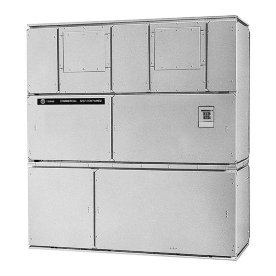
- Page 9 Overview this manual, the acronym UCM refers to the entire control Figure 1. IntelliPak CSC Modular Series Unit system network. These modules perform specific unit functions using proportional/integral control algorithms. They are mounted in the unit control panel and are factory wired to their respective internal components.
- Page 10 Model Number Description Commercial Self-Contained Modular Series Digit 1 — Unit Model Digit 13— Flexible Horizontal Discharge Digit 20— Heating Type Plenum Type S = Self-Contained A = Steam coil, LH B = STD plenum w/ factory-cut holes B = Hot water coil, LH C = Low plenum w/ factory-cut holes C = Electric heat, 1 stage E = Std plenum w/ field-cut holes...
- Page 11 Model Number Description Digit 27 — Waterside Economizer Digit 33 — Control Interface Options A = Mechanical clean full capacity (4-row) A = Generic BAS Module; 0-5 Vdc (GBAS) B = Mechanical clean low capacity (2-row) B = Ventilation Override Module (VOM) C = Chemical clean full capacity (4-row) D = Remote Human Interface (RHI) D = Chemical clean low capacity (2-row)
- Page 12 20 x 25 x 2 Notes: Compressors are Trane 3-D™ scroll. All units operate with R-410A. Water Cooled units that ship together ship with full operating charge. Ship-separate water-cooled units ship with dry nitrogen charge. Field refrigerant system charge required.
- Page 13 11219 x 1575 Notes: Hot water and steam heating coils have Prima-Flo® fins and do not have turbulators. For coil capacities, use TOPSS™ (Trane Official Product Selection Program). Table 3. Waterside economizer coil physical data—SCXG 20, 25, 30, 35 Type...
- Page 14 Specify Note: Notify your Trane representative of the damage and the type and extent of the damage on the bill of lading arrange for repair. Have the carrier inspect the before signing.
- Page 15 Pre-Installation Unit Protective Covers • Do not remove damaged material from receiving location. Remove shipping protection coverings from human • Take photos of the damage, if possible. interface panel (HI) at control panel, filter box (or air inlet opening), discharge air opening, and optional variable •...
- Page 16 Pre-Installation Figure 3. Fan Isolator Locations Figure 4. Supply fan horizontal isolation shipping bracket SCXG-SVX01Q-EN...
- Page 17 Dimensional Data Figure 5. SCWG/SIWG (in.) SCXG-SVX01Q-EN...
- Page 18 Dimensional Data Figure 6. SCWG/SIWG detail “A” (in.) Note: When unit is ordered with horizontal supply, ensure that all applicable codes are considered when installing equipment. Special attention should be made to over head clearances of unit/ducting to meet code requirements. Table 4.
- Page 19 Dimensional Data Steam, Hot Water and Electric Heat Coils Steam Coils Figure 8. Steam coil: left connections 92 3/4" 22 1/2" 73 1/2" 53 13/16" 3 5/16" VERTICAL 15 7/8" DISCHARGE 1" 3/4" (4X) ISOLATOR ELECTRICAL 30 7/8" MOUNTING LOCATION 40 15/16"...
- Page 20 Dimensional Data Hot Water Coils Figure 10. Hot water coil: left-hand connections Figure 11. Hot water coil: right-hand connections Table 5. Hot water coil dimensions and weight (in) (lbs) Weight Coil One Row 53-3/4 4-7/8 73-1/2 16-5/8 6-3/4 7-1/2 23-1/8 37-1/4 1-3/4 2-1/2...
- Page 21 Dimensional Data Waterside Economizer Electric Heat Coils Figure 12. Electric Heat Coil Figure 14. Waterside Economizer Table 6. Electric heat coil dimensions and weight (in) (lbs) Weight Unit Size Table 8. Waterside economizer weights (in)(lbs) 20 tons 70-1/4 4-7/8 11-1/2 25 tons 70-1/4 4-1/8...
- Page 22 Dimensional Data Airside Economizer Figure 16. Airside economizer Figure 15. Detail “B” (top) and detail “A” (bottom) Table 9. Airside economizer sizes and dimensions (in.) F (1) F (2) G (1) G (2) H (1) Size SCWG/SIWG 65-5/8 74-1/4 39600 56-1/2 49-3/4 23-1/4...
- Page 23 Dimensional Data Service Clearances See figure and table below for recommended service and code clearances. Figure 17. Top view of self-contained unit showing recommended service and code clearances air inlet 18” minimum 36” table minimum Control Panel 42” minimum Table 10. Service and code clearance requirements Purpose Side Distance...
- Page 24 Installation - Mechanical Unit Handling WARNING Heavy Objects! WARNING Placing, assembling, and/or suspending more than Improper Unit Lift! one module/subassembly at a time could result in Failure to properly lift unit in a LEVEL position could death, serious injury, or equipment damage. result in unit dropping and possibly crushing Always place, assemble, and suspend modules/ operator/technician which could result in death or...
- Page 25 Installation - Mechanical Figure 19. Split-apart unit gravity block location Figure 20. Split-apart modular unit proper rigging (L) and fan section (R) Figure 21. Assembled modular unit proper rigging SCXG-SVX01Q-EN...
- Page 26 Installation - Mechanical Skid Removal 4. Remove the protective shipping covers from the unit. 5. Verify isolators are properly tightened for operation. The unit ships on skids to provide forklift locations from the front or rear. The skid allows easy maneuverability of the Notes: unit during storage and transportation.
- Page 27 CPC to the internal CPC in the top control panel. depending upon unit options. 14. If the unit has the mixed air temperature option, route Note: Trane strongly recommends you consult a vibration the capillary tube on back of the filter rack. specialist before double-isolating the unit. Double Units with Thermostat Only isolation is not recommended.
- Page 28 Air Heating and Air Conditioning Systems (NFPA 90B). Make duct connections to the unit with a flexible material such as heavy canvas. If a fire hazard exists, Trane recommends using Flexweave 1000, type FW30 or equivalent canvas. Use three inches for return duct and three inches for discharge duct.
- Page 29 Installation - Mechanical Figure 25. Duct connection recommendations Unit Preparation 3. Open the access door and remove the damper cabinet’s support legs and its hanging bracket. The Discharge Duct support legs are secured to the skid, and the hanging 3 Fan bracket is secured with wire ties to an inside flange 3-inch Diameters...
- Page 30 Installation - Mechanical of pneumatic tubing located inside damper cabinet. Note: Four (4) condenser waterline drain plugs ship in a Route tubes through cabinet’s front upper panel (0.25 bag in the left end of the unit. The installer must field dia.
- Page 31 Installation - Mechanical Water Temperature Requirements Figure 28. Direct condenser connections Do not allow the entering water temperature to go below 54°F (12.2°C) on units with constant water flow (basic piping).This will cause the compressors to shut down and the mechanical cooling function will lockout. However, the economizer (if enabled) will continue to function.
- Page 32 Installation - Mechanical 10. Install the pipe insulation on all pipe line to prevent Figure 32. Waterside economizer with left-hand factory piping tubing assembly sweating 11. Install the rear panels. 12. Re-install the filter rack on the back of the economizer coil box and affix with screws provided.
- Page 33 Installation - Mechanical Table 14. Waterside economizer part descriptions— Figure 34. Detail view of ship-separate tubing left-hand piping (continued) assemblies for waterside economizer right-hand piping Part Description Item Assembly #3 Assembly #4 Tube; 2-5/8" x 16-7/8" Tube; 2-5/8" x 22-5/8" Waterside Economizer with Right-hand Factory Piping Components Figure 33.
- Page 34 Actuator Assembly Refrigerant System Installating the Hydronic Coil Trane Water Cooled Self-Contained units are available in complete system or a “Split Apart” configuration. Complete WARNING systems are factory charged with R-410A refrigerant. Split...
- Page 35 Installation - Mechanical NOTICE WARNING Explosion Hazard! Compressor Damage! Failure to properly regulate pressure could result in a Failure to follow these instructions could result in violent explosion, which could result in death, serious compressor failure. injury, or equipment or property-only-damage. If it becomes necessary to remove or recharge the system with refrigerant, it is important that the When using dry nitrogen cylinders for pressurizing...
- Page 36 Installation - Electrical Unit Wiring Diagrams Voltage Range Voltages must be within ±10% the nameplate voltage. Specific unit wiring diagrams are provided on the inside of Ensure the unit voltage is balanced by measuring at the the control panel door. Use these diagrams for connections compressor terminals.
- Page 37 Installation - Electrical Selection Procedures Table 17. Number of compressors per unit RLA = rated load amps SCWG/SIWG Compressor LRA = locked rotor amps 10 HP Fan motor LRA = locked rotor amps, N.E.C. Table 430 - 15 HP FLA = full load amps, N.E.C. Table 430 - 150 Table 18.
- Page 38 Variable Frequency Drive Without or other energy storing components provided by Bypass Trane or others, refer to the appropriate manufacturer’s literature for allowable waiting periods Table 22. W/O Bypass VFD Frame Sizes for discharge of capacitors. Verify with a CAT III or IV...
- Page 39 Installation - Electrical Figure 35. Frame A3: without bypass Weight = 14 lbs (6.350 Kg) SCXG-SVX01Q-EN...
- Page 40 Installation - Electrical Figure 36. Frame B1: without bypass Weight = 51 lbs (23.133 Kg) SCXG-SVX01Q-EN...
- Page 41 Installation - Electrical Figure 37. Frame B2: without bypass Weight = 60 lbs (27.216 Kg) SCXG-SVX01Q-EN...
- Page 42 Installation - Electrical Figure 38. Frame C1: without bypass Weight = 91 lbs (41.277 Kg) Variable Frequency Drive With Bypass Table 23. With bypass VFD frame sizes 200V 460V 575V Notes: Figure 39, p. 43 through Figure 42, p. 46 for frame size details.
- Page 43 Installation - Electrical Figure 39. Frame A3: with bypass Weight = 35 lbs (15.876 Kg) SCXG-SVX01Q-EN...
- Page 44 Installation - Electrical Figure 40. Frame B1: with bypass Weight = 85 lbs (38.555 Kg) SCXG-SVX01Q-EN...
- Page 45 Installation - Electrical Figure 41. Frame B2: with bypass Weight = 105 lbs (47.627 Kg) SCXG-SVX01Q-EN...
- Page 46 Installation - Electrical Figure 42. Frame C1: with bypass Weight = 145 lbs (65.771 Kg) Static Pressure Transducer exceed 250ft for 1/4” OD tubing or 500ft for 3/8” OD tubing. Installation (VAV units only) Installing the Transducer Supply air static pressure controls the inverter option. A static pressure head assembly ships separate in control Use the following procedure to properly install the static panel for field installation in the supply air duct work.
- Page 47 For variable frequency drives or other energy storing components provided by Trane or others, refer to the appropriate manufacturer’s literature for allowable waiting periods for discharge of capacitors. Verify with a CAT III or IV voltmeter rated per NFPA 70E that all capacitors have discharged.
- Page 48 “Unitary Accessories (ACC)”/“UPG Rooftop, Packaged Heat Pump, Split System Accessories (ACC)”. Contact your local Trane sales office. Following is a full description of zone sensors and their functions. Following is a full description of zone sensors and their functions. See Table 33, p.
- Page 49 Installation - Electrical remote sensors. When this sensor is wired to one of these • Zone sensor for ICS™ systems remote zone sensors, wiring must be 18 AWG shielded • Zone temperature averaging twisted pair (Belden 8760 or equivalent). Refer to the When used as a remote sensor for standard zone sensor, specific zone sensor for wiring details.
- Page 50 Zone temperature sensor with timed override This electronic analog sensor features single setpoint Zone Sensor Installation capability and timed override with override cancellation. It is used with a Trane® Integrated Comfort™ system. WARNING BAYSENS073 features and system control functions Hazardous Voltage w/Capacitors!
- Page 51 Installation - Electrical Mounting Location Table 26. Zone sensor maximum lengths and wire size Mount the sensor on the wall in an area with good air circulation at an average temperature. Avoid mounting Distance from Unit to Recommended Wiring Size Controller space temperature sensor is areas subject to the following conditions:...
- Page 52 Installation - Electrical Remote Human Interface Panel The time clock, a “Digi 20” by Grasslin, is inside the control panel, but accessible with the control panel door closed. Installation This same type timer is also used for programmable night setback/morning warm up. Programming instructions for Human Interface (HI) Panel the “Digi 20”...
- Page 53 Installation - Electrical Location Recommendations Procedure The HI microprocessor module is mounted inside a molded Refer to Figure 48, p. 54 and follow the procedure below plastic enclosure for surface mounting. It is not for mounting the remote HI panel on a 4" x 4" electrical weatherproof.
- Page 54 Installation - Electrical Wall Mounting the RHI Panel 4. With the enclosure in the correct position, remove the enclosure and drill the necessary holes in the surface 1. Prior to mounting the panel, the microprocessor module for the appropriate fasteners, (plastic anchors, molly must be removed from the enclosure.
- Page 55 Installation - Electrical Communication Link (Shielded Twisted unit. Pair) Wiring Field wiring for both the low voltage power and the shielded twisted pair must meet the following requirements: 1. Trim the outer covering of the shielded cable back Important: To prevent control malfunctions, do not run low approximately 1 inch.
- Page 56 The “Digi 20” electronic time switch is freely programmable or other energy storing components provided by for each day of the week in one minute increments. For Trane or others, refer to the appropriate easy and quick programming, the following 4 block manufacturer’s literature for allowable waiting periods programs are available: for discharge of capacitors.
- Page 57 Installation - Electrical 2. To change a program, select that program as outlined is on, or switch it on if it is off). A hand symbol appears in in step 1. Enter the time of day and days of week just as the display to indicate the override is active.
- Page 58 Operating Principles Control Sequences of Operation Figure 50. Typical cycling morning warm-up cycle Occupied/Unoccupied Switching • Night setback zone sensor • Field-supplied contact closure (hard wired binary input Ventilation to RTM) Enable • Tracer Summit Morning • Factory-mounted time clock Warmup Temperature Field-Supplied Occupied/Unoccupied...
- Page 59 Operating Principles Timed Override Activation—ICS™ Zone Temperature Control (Unit Model Number Digit 9 = 4 or 5) This function is operational whenever the unit’s RTM module is used as the zone temperature sensor source, A zone sensor located directly in the space sends input to which can be set at the HI panel.
- Page 60 Operating Principles with the highest priority attempts cooling first. Once it is ensure it is greater than 54°F or if not, it will lock out operating at its maximum, and if additional cooling is cooling. necessary, the other economizer enables before Auto Changeover (Units with Heat Only) mechanical cooling begins.
- Page 61 Operating Principles Thermostatic Expansion Valve For both outdoor air cooling reset and heating reset, there are three user defined parameters that are adjustable NOTICE through the human interface panel: Compressor Damage! • Beginning reset temperature • Ending reset temperature Do not operate with water loops with less than five minutes circulation time as it could result in poor •...
- Page 62 Operating Principles not turn on until they have been off for at least three The supply air temperature control band is centered around minutes. Normal operating conditions are established on supply air temperature setpoint and is adjustable from 2 to an individual compressor basis.
- Page 63 UCM will not shut the compressor required. Trane assumes no responsibility for off during the first two to three minutes after startup. This equipment failures which result from untreated or prevents possible nuisance trips during low ambient start improperly treated water, or saline or brackish water.
- Page 64 Operating Principles Constant water flow is for condenser pumping systems that entering water temperature is not below the unit’s entering are not capable of unloading the water-pumping system. mixed air temperature by at least the water economizer Variable water flow maximizes energy saving by unloading approach temperature.
- Page 65 Operating Principles saturated condenser temperatures change again. Both valves close whenever mechanical cooling is not required, and in the event of a power failure. If the unit does not have a waterside economizer then variable water flow is automatically active with intermediate piping.
- Page 66 Operating Principles and the HI will display a diagnostic. The unit will continue to BTUs/lb. default (adjustable 19-28 BTUs/lb). During run until you replace the air filters. occupied mode, the outside air damper opens to 15% (adjustable 0-100% at the HI) for ventilation purposes. A field installed indicator device may be wired to relay Also, the ability to alter the outside air damper position to terminals to indicate when filter service is required.
- Page 67 Operating Principles steel and rotate on rustproof nylon bushings. A factory field-provided modulating actuator. In occupied mode, the installed 24V modulating spring return actuator controls output drives to the maximum position. both damper positions. Airside Economizer Interface Airside Economizers with Traq Damper Units with airside economizer interface are equipped with Outside air enters the unit through the Traq™...
- Page 68 Controls Points List ECEM Module Analog Inputs RTM Module • Return air temperature Binary Inputs • Return air humidity • Emergency stop In addition, units with a VOM have: • External auto/stop Binary Inputs • Unoccupied/occupied • VOM mode A, unit off •...
- Page 69 Controls on information received from other unit modules, sensors, manual reset diagnostic. External control of the fan is not remote panels, and customer supplied binary inputs. It recommended. initiates supply fan, exhaust fan, exhaust damper, or VAV Drive Max Output variable frequency drive output, and airside economizer operation based on that information.
- Page 70 Controls @ 24 Vdc minimum. This input will override all VOM inputs, Table 33. RTM sensor resistance vs. temperature (continued) if the VOM option is on the unit. Occupied/Unoccupied Contacts Resistance Resistance Temp °F Temp °F V ohms V ohms To provide night setback control if a remote panel with night 46.94 9.30...
- Page 71 (IPCB). Model number digit 32 (=2) indicates if the ICPB be changed unless they are locked using the HI. Once was ordered with the unit. If not, contact your local Trane locked, the ventilation sequences cannot be unlocked. representative to order an ICPB kit for field installation. The The compressors and condenser fans disable during the RHI can be located up to 1,000 feet (304.8 m) from the unit.
- Page 72 EXHAUST Sequence “C” Module With the building’s exhaust fans running and the unit’s (LCI/BCI - Optional - used on units with Trane ICS™ or 3rd supply fan off, the conditioned space becomes negatively party Building Automation Systems) pressurized. This is desirable for clearing the area of smoke when necessary;...
- Page 73 Generic Building Automation System Module Option Generic building automation system module (GBAS) provides broad control capabilities for building automation systems other than Trane’s Tracer® system. A field Figure 57. Velocity pressure transducer/solenoid provided potentiometer or a 0-5 Vdc signal can be applied assembly...
- Page 74 Controls GBAS Demand Limit Relay (Binary Input) unit wiring diagram for GBAS input wiring and the various desired setpoints with the corresponding DC voltage The GBAS allows the unit to utilize the demand limit inputs. function by using a normally open (N.O.) switch to limit the Any of the setpoint or output control parameters can be electrical power usage during peak periods.
- Page 75 Trane assumes no responsibility for current exceeds the breakers “must trip” value. During a equipment failures which result from untreated or request for compressor operation, if the Compressor improperly treated water, or saline or brackish water.
- Page 76 Controls Low Ambient Compressor Lockout Module detects a problem outside normal parameters, it turns any operating compressor(s) on that circuit “Off”, Utilizes an analog input device. When the system is locks out all compressor operation for that circuit, and configured for low ambient compressor lockout, the initiates a manual reset diagnostic.
- Page 77 The static limit is adjustable at the HI. High Duct Temp Thermostat Option On Units with a LCI-I The high duct temperature thermostats are binary input devices used on units with a Trane communication SCXG-SVX01Q-EN...
- Page 78 Pre-Startup Pre-Startup Checklist • Verify that all ductwork conforms to NFPA 90A or 90B and all applicable local codes Complete this checklist after installing unit to verify all recommended installation procedures are complete before Water-Cooled Unit Piping startup. This does not replace the detailed instructions in the appropriate sections of this manual.
- Page 79 Start-up WARNING SLOWLY meter into the suction line only as much R- 410A as needed to close the low pressure cutout. Use Live Electrical Components! the VAPOR charging connection. If possible, plan to Failure to follow all electrical safety precautions when use this entire refrigerant bottle on the same unit in exposed to live electrical components could result in order to minimize fractionalization.
- Page 80 Start-up NOTICE NOTICE Compressor Damage! Compressor Damage! Failure to follow instructions below could result in Failure to follow instructions below could result in compressor damage. compressor failure and/or reduced compressor life. Improper power phasing will cause compressor to run To prevent compressor liquid slugging, only add backwards.
- Page 81 Start-up Startup Log Unit: Unit Location: Unit Voltage Evaporator Evaporator fan motor horsepower: Evaporator fan motor amps: Evaporator fan rpm (actual): Evaporator system static (from test and balance Supply duct static: Return duct static: report or actual readings) Evaporator system cfm (test and balance sheet or actual tested): Evaporator Air Conditioners (with all compressor operating) Entering...
- Page 82 Follow proper lockout/ Trane or others, refer to the appropriate tagout procedures to ensure the power cannot be manufacturer’s literature for allowable waiting periods inadvertently energized.
- Page 83 Disconnect all electric power, including remote or other energy storing components provided by disconnects and discharge all motor start/run Trane or others, refer to the appropriate capacitors before servicing. Follow proper lockout/ manufacturer’s literature for allowable waiting periods tagout procedures to ensure the power cannot be for discharge of capacitors.
- Page 84 For variable frequency drives or other energy storing components provided by Trane or others, refer to the appropriate manufacturer’s literature for allowable waiting periods for discharge of capacitors. Verify with a CAT III or IV...
- Page 85 Maintenance Table 40. AO smith bearing lubrication schedule Table 43, p. 85. If necessary, readjust belt tension. (continued) Table 43. Fan shaft bearing torques 1800 rpm 3 yrs 1 yr 140-180 6 mths Recommended Torque Setscrew Hex-Size 1 1/2 yrs 400-440 8 mths 4 mths...
- Page 86 Maintenance To adjust belt tension see Figure 59, p. 85 and perform the 5. Verify tension is adjusted properly. following procedure: Recommended belt tension range values are on the unit 1. Loosen bolts A, B, and E on both sides of the sliding fan scroll.
- Page 87 Do not work in confined spaces where refrigerant or concerns with R-410A, please contact your local other hazardous, toxic, or flammable gas may be Trane representative. leaking. Refrigerant or other gases could displace available oxygen to breathe, causing possible Note: These service procedures require working with refrigerant.
- Page 88 Maintenance design pressures. If testing complete system, low side Note: Use 40-45% silver brazing alloy (BAg-7 or BAg- design pressure is maximum. 28) on dissimilar metals. Use BCup-6 brazing alloy on copper-to-copper joints. 4. Check piping and/or components as appropriate for leaks.
- Page 89 Maintenance • Start vacuum pump. After several minutes the gauge read the actual system pressure. Let system equalize for reading will indicate the maximum vacuum the pump is approximately 15 minutes. This is referred to as a “standing capable of pulling. Rotary pumps should produce vacuum test”...
- Page 90 Maintenance Compressors Scroll Compressor Failure Diagnosis and Replacement If compressor failure is suspected, refer to COM-SVN01 for detailed information regarding compressor failure diagnosis and replacement of scroll compressors. Components Figure 64. Typical water-cooled compressor section components SCXG-SVX01Q-EN...
- Page 91 Maintenance Note: Tighten bolts to 38 ft. lbs. evaporator is directly behind the economizer. To clean between the coils, remove the sheet metal block off. Access the block off by removing the corner panels on Cleaning Coil Fin the left or right rear side of the unit. WARNING •...
- Page 92 8. Straighten any coil fins that may be damaged with a fin equipment damage. rake. Drain and vent coils when not in use. Trane recommends glycol protection in all possible freezing 9. Replace all panels and parts and restore electrical applications.
- Page 93 For variable frequency drives or other energy storing components provided by 1. Inspect unit air filters. Clean or replace if airflow is Trane or others, refer to the appropriate blocked or if filters are dirty. manufacturer’s literature for allowable waiting periods 2.
- Page 94 Maintenance 8. Check and record operating pressures. sheaves. 1. Inspect, clean, and tighten all electrical connections. Semi-Annual Maintenance 2. Visually inspect the entire unit casing for chips or 1. Verify the fan motor is properly lubricated. Follow corrosion. Remove rust or corrosion and repaint lubrication recommendations on the motor tag or surfaces.
- Page 95 Diagnostics Troubleshooting charge, malfunctioning of expansion valves, damaged compressors, etc. will result in pressure variations which System Checks are outside the normal range. Note: If phasing at the main incoming power terminal is WARNING incorrect, switch two of the three incoming power Live Electrical Components! leads.
- Page 96 Diagnostics Additional Diagnostic Resources Menu” and “Diagnostic Menu” sections in the programming guide. Refer to the following text for general diagnostic and Refer to the Self-Contained Programming Guide, PKG- troubleshooting procedures. SVP01, for specific unit programming and troubleshooting information. In particular, reference the “Service Mode Category Diagnostic Auto Reset S/A Static Pressure Limit...
- Page 97 Diagnostics Category Diagnostic Condenser Temp Sensor Failure—Circuit 1, 2, 3, or 4 The saturated condenser temperature input is out of range for circuit #1, 2, 3, or 4. Problem Sensor resistance should be between 830 ohms (200°F) and 345.7 ohms (-40°F). If so, check field/unit wiring between sensor and MCM/SCM. Check Reason for The unit is reading a signal that is out of range for the circuit #1, 2, 3, or 4 saturated condenser temperature sensor.
- Page 98 Diagnostics Category Diagnostic Time to React 10 sec < T < 20 sec Diagnostic Text (Human “ENT COND WATER TEMP SENSOR FAIL” Interface Display) Actions to be A “Lockout All Ckts” request is issued to the “Compressor Staging Function” Initiated An automatic reset occurs after the entering condenser water temperature input returns to within range continuously for 15 seconds.
- Page 99 Diagnostics Category Diagnostic Heat Failure The heat has failed. (Electric heat unit)Typically, this is because the electric heat section became too hot. Problem The heat fail input on the heat module was closed: Reason for • For more than 80 seconds, Diagnostic •...
- Page 100 Diagnostics Category Diagnostic Low Pressure Control Open—Circuit 1, 2, 3, or 4 The Low Pressure Control (LPC) for Ckt #1, 2, 3, or 4 is open. Problem State of refrigerant charge for ckt #1, 2, 3, or 4. Check Reason for The Ckt # 1 LPC input is detected open as described in the compressor protection function.
- Page 101 Diagnostics Category Diagnostic If have an external sensor connected to the NSB panel zone sensor input, then the internal NSB panel zone sensor should be disabled. Verify Check sensor resistance. If in valid range, check wiring between the sensor and NSB panel. NSB Panel Comm Failure The RTM has lost communications with the night setback panel (programmable zone sensor).
- Page 102 Diagnostics Category Diagnostic Reason for The unit is reading a signal that is out of range for the return air humidity sensor (humidity < 5% or humidity > 100%). Diagnostic The economizer enable r.e. enthalpy function reverts to reference enthalpy changeover (“Level 2”) control. Reaction Reset (PMR) An automatic reset occurs after the RA humidity input returns to its allowable range continuously for 10 seconds.
- Page 103 Diagnostics Category Diagnostic Reason for The RTM has lost communication with the SCM. Diagnostic A “lockout” request is sent to the compressor staging control function. A fail-safe function in the SCM will cause all SCM outputs to be zeroed Controls and de-energized.
- Page 104 Diagnostics Category Diagnostic Controls The default HI-set SA temp heating setpoint becomes the active SA temp heating setpoint. Reaction Reset (PAR) An automatic reset occurs after the SA temp heating setpoint input returns to within range for 10 continuous seconds, or after a different Required SA temp heating setpoint selection source is user-defined.
- Page 105 Diagnostics Category Diagnostic The INFO diagnostic is cleared when the supply fan VFD bypass is deactivated. Reset LCI Module Comm Failure Problem The RTM has lost communication with the LCI. Check field/unit wiring between RTM and LCI module. Check Reason for The RTM has lost communication with the LCI module.
- Page 106 Diagnostics Category Diagnostic Controls The active unoccupied zone heating setpoint reverts to the default value. Reaction Reset (PAR) An automatic reset occurs after the designated unoccupied zone heat setpoint input returns to its allowable range for 10 continuous Required seconds, or after the user defines a different, valid unoccupied zone heating setpoint selection source. VCM Communication Failure Problem The RTM has lost communication with the VCM.
- Page 107 Diagnostics Category Diagnostic Reset An automatic reset occurs after one complete set of IPC packets is received. Required WSM Mixed Air Temp Sensor Fail Activation Temperature <-50°F or temperature >209°F, and sensor is selected for use by “waterside economizer temperature enable function” or “preheat Conditions function”...
- Page 108 Wiring Diagrams Note: For easier access, published unit wiring diagrams lines) will become available via e-Library instead of (individual, separate diagrams for unitary product through wiring manuals after 2007. Description Number Field Wiring Diagram W/VFD S*WG 20 -35T 2307-8264 Schematic Diagram With VFD W/Bypass RTM Module S*WG 20-35T 2307-8266 Schematic Diagram With VFD W/Bypass S*WG 20-35T 2307-8272...
- Page 109 Notes SCXG-SVX01Q-EN...
- Page 110 Notes SCXG-SVX01Q-EN...
- Page 111 Notes SCXG-SVX01Q-EN...
- Page 112 For more information, please visit trane. com or tranetechnologies.com. Trane has a policy of continuous product and product data improvements and reserves the right to change design and specifications without notice. We are committed to using environmentally conscious print practices.