Trane IntelliPak I Programming, Troubleshooting Manual
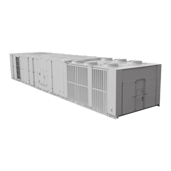
Commercial single zone rooftop air conditioner with variable air volume (vav) controls
Hide thumbs
Also See for IntelliPak I:
- Installation, operation and maintenance manual (192 pages) ,
- Installation operation & maintenance (116 pages) ,
- User manual (109 pages)
Table of Contents
Advertisement
Programming
Troubleshooting
Guide
IntelliPak™ I and II
Commercial Single Zone Rooftop Air
Conditioner with Variable Air Volume (VAV)
Controls
Model Number
IntelliPak I models
IntelliPak II models
April 2010
S*HF*20-75, S*HL*20-75, S*HG*90-130, S*HK*90-130 Ton
W*HB, W*HE
S*HJ090-162, W*HCA-C
RT-SVP04F-EN
Advertisement
Table of Contents
Troubleshooting

Related Manuals for Trane IntelliPak I


Summary of Contents for Trane IntelliPak I
-
Page 1: Troubleshooting Guide
Programming Troubleshooting Guide IntelliPak™ I and II Commercial Single Zone Rooftop Air Conditioner with Variable Air Volume (VAV) Controls Model Number IntelliPak I models S*HF*20-75, S*HL*20-75, S*HG*90-130, S*HK*90-130 Ton W*HB, W*HE IntelliPak II models S*HJ090-162, W*HCA-C RT-SVP04F-EN April 2010... -
Page 2: Table Of Contents
UCM Control System Human Interface Module (Local = 1U2, Remote = 9U13 IntelliPak II) (1U65 IntelliPak I) ..........13 Unit Operation Keys . -
Page 3: General Information
General Information Commonly Used Acronyms For convenience, a number of acronyms and abbreviations are used throughout this manual. These acronyms are alphabetically listed and defined below. Table 1. Acronyms Act = active HGBP = Hot Gas Bypass AH = Air Handler HGP = Hot Gas Bypass Annunc = Annunciator Hi = high... -
Page 4: Glossary Of Terms
General Information Pot = potentiometer SZ = single-zone (unit airflow) PPM = parts per million TCI = Tracer communications interface (module) HEAT = where all caps HEAT (module) Press = pressure Propor = proportional Temp = temperature psig = pounds-per-square-inch gauge pressure UCM = Unit Control (Module) PWS = part-winding start Unocc = unoccupied... - Page 5 SETPOINT. The purpose is to prevent no-flow scroll compressor operation. Comm3/4. Trane proprietary network communication protocol. Comm5. Trane's implementation of LonTalk or BACnet (an open network communication protocol). Condenser Pressure. The saturated condenser pressure measured on each circuit's(2) condenser section on Evaporative Condenser units.
- Page 6 General Information Evap Diff. Evap Diff is a calculated value indicating performance of a refrigeration system. It is calculated by determining the difference between the Entering and Leaving temperatures of the evaporator. If this value rises too high it may indicate a problem with the system.
-
Page 7: Ucm Control System
Target. Dynamic control point the unit is controlling to at any given time. UCM Control System Trane Large Commercial Rooftop Units are controlled by a microelectronic control system that consists of a network of modules and are referred to as Unit Control Modules (UCM). - Page 8 VCM Auxiliary Temperature input. The preheat unit is user-supplied. Multi Purpose Module (1U9 IntelliPak II) (1U105 IntelliPak I) (Optional - used with Return Fan Control) The MPM supports the function of return plenum pressure control by providing inputs...
- Page 9 Switches 1 and 2 “Off” , Switch 3 “On” . BACnet Communication Interface Module (BCI) (1U66 IntelliPak II) (1U104 IntelliPak I) (Optional - used on units with Trane ICS or 3rd party Building Automation Systems) The BACnet Communication Interface module expands communications from the unit...
- Page 10 General Information Human Interface Module (Local = 1U2, Remote = 9U13 IntelliPak II) (1U65 IntelliPak I) The Human Interface (HI) Module illustrated in Figure 1 is the device which enables the customer, building owner, or contractor, to communicate to the Rooftop unit the necessary parameters for unit operation such as cooling and heating SETPOINTs, demand limiting, ventilation override modes, etc.
- Page 11 General Information Figure 1. Human Interface Module Menu Keys The six keys illustrated in Figure 2 in the MENU area (STATUS, SETPOINTS, SETUP , CONFIGURATION, DIAGNOSTICS, and SERVICE MODE) are used to bring up the various interactive menus where the user inputs and accesses unit operating data. Pressing these keys will display the initial screen for the menu designated by the key’s name.
- Page 12 General Information SETPOINTS Key Pressing the SETPOINTS key will cause the LCD screen to display the first of the SETPOINT screens where the operator will designate default temperature and pressure SETPOINTs. While scrolling through the SETPOINT screens, pressing this key again will cause the LCD to display the first SETPOINT screen.
-
Page 13: Unit Operation Keys
General Information ENTER Key This key will confirm the new values that were designated by pressing the + (Plus) or - (Minus) keys at all edit points. When viewing status and diagnostics screens, it has no function. CANCEL Key After changing data, at an editable screen, but before confirming it with the ENTER key, pressing the CANCEL key will return the data to its previous value. - Page 14 General Information STOP Key Pressing the STOP key will cause the unit to transition to the stop state. If the current display is editable, pressing the STOP key will cancel the desired edit. TEST START Key (SERVICE) Pressing this key while viewing any screen in the SERVICE Mode menu will start the service test.
- Page 15 General Information General Status Display Anytime the rooftop unit is powered up, or the STATUS, AUTO, or STOP keys are pressed, the unit mounted Human Interface will display one of the following four general status display screens. The operator will then be able to enter keystrokes which will allow him to navigate through a set of menus and submenus in order to provide/ access various monitoring, SETUP , and configuration information.
- Page 16 General Information Stop by Network Supply Fan ON Used With: Top Status Display (Shown when unit is off or stopped) Initializing Diagnostics Possible Values: Top/Left field: Unit Off, Unit Stopped, External Stop, Emergency Stop, Stop by Network, Unit Starting, Service Mode Off; Top/Right field: Supply Fan OFF, Supply Fan ON;...
- Page 17 General Information Freeze Avoidance OA Flow Range (Blank) 0-5980 CCFM (Blank) CVZT VVDA CVDA VVDA OA Flow ___ CCFM Supply Fan ________ ______ ____ ___________ Occupied Heat Unoccupied Cool (Blank) Morning WU 0-100% OA Dmpr Diagnostics Daytime WU Dehumid Standby Purge Shutdown Humidify...
- Page 18 General Information VOM Active If at power up the unit is running and has entered a Ventilation Override mode of operation, the following display will appear on the Human Interface LCD screen. VO Mode in Operation (A,B,C,D,E) Ventilation Override Mode ______ _____________ Trouble Indicator...
- Page 19 General Information To adjust Adjustable Function Factory Preset Changed To Press... Control Parameters Default system mode Auto SETUP Demand limit definition for cooling None SETUP Demand limit definition for heating None SETUP Economizer control enable type Drybulb SETUP Exhaust enable point SETUP Morning Warmup type Full...
- Page 20 General Information Design Min CO (DCV) 1000 PPM SETPOINTS DCV Min CO /400 SETPOINTS DCV Min OA Flow Deadband 5 CCFM SETPOINTS Design Min OA Flow (DCV) 220 CCFM SETPOINTS DCV Min OA Flow 67 CCFM SETPOINTS Design Min OA Damper Position(DCV) SETPOINTS DCV Min OA Damper Position SETPOINTS...
- Page 21 General Information Occupied zone heating Default SETUP Space Pressure Default SETUP Unoccupied zone cooling Default SETUP Unoccupied zone heating Default SETUP Economizer Dry Bulb Enable Default SETUP Occupied Dehumidification Default SETUP Unoccupied Dehumidification Default SETUP Supply Air Reheat Default SETUP OA Damper Actuator (if equipped) Actuator SETUP DIRECT...
- Page 22 General Information Supply Fan IGV/VFD (if equipped) Actuator SETUP Direct Acting SETUP Max Stroke Time 30 sec SETUP Max Voltage 10 VDC SETUP Min Voltage 2 VDC SETUP Exhaust Damper/VFD (if equipped) Actuator SETUP Direct Acting SETUP Max Stroke Time 60 sec SETUP Max Voltage...
-
Page 23: Password Protected Screens
SETUP Ventilation override definition See Definitions SETUP Reference note applies to IntelliPak I units only. Note 1. Note 2. Reference note applies to IntelliPak II units only. Password Protected Screens Some of the operating displays on the Human Interface LCD screens and require a password to change. - Page 24 General Information Diagnostic Reset is Password Protected Please Enter Password: ____________ Press the + or - keys in this sequence ( - + + ) to access this restricted screen. 2. Press the ENTER key to confirm the password and Lock the definitions. 3.
-
Page 25: System Operating Status
System Operating Status STATUS Menu The STATUS menu is used to view various operating conditions such as temperatures and humidity levels. It’s used to view unit component status such as fan, compressor, heater, and economizer operation, as well as SETPOINT status. The screens shown in this section are for example only. - Page 26 System Operating Status RTM Supply Fan Relay: Used With: All Units RTM Supply Airflow Proving: FLOW Possible Values: Fan = ON, OFF Airflow = FLOW, NO FLOW 1. Pressing the NEXT key will scroll forward through the screens. 2. Pressing the PREVIOUS key will scroll backwards to view the previously displayed screen. 3.
- Page 27 System Operating Status Electric Heat: ENABLED Used With: All units with Electric Heat installed. Stage: 6 K11: ON K12: ON K1: ON Possible Values: Electric Heat: ENABLED, DISABLED By Setup, 1. Press the NEXT key until the following screen is displayed. LIMITED By Demand Limit (If applicable) Stage: 0,1,2,3,4,5,6...
- Page 28 System Operating Status Dehumidification Status: DISABLED Used With: All IntelliPak with Dehumidification option installed. by Comfort Control Override is Active 1. Pressing the NEXT key will scroll forward through the screens. Top Line Possible Values: ENABLED, DISABLED 2. Pressing the PREVIOUS key will scroll backwards to view the Bottom line Possible Values: See previously displayed screen.
- Page 29 1. Pressing the NEXT key will bypass this section. Compressor Relay KXX XXXXXX Used With: IntelliPak I Rooftop Units and Air Handlers with DX XXXXXXXXXXXXXXXXXXXXXXXXXXXXXXXXX (MORE) Cooling installed. 1. Pressing the NEXT key will scroll forward through the screens.
- Page 30 System Operating Status Compressor Relay K3 XXXXXX Used With: All IntelliPak I Rooftop Units and Air Handlers with DX XXXXXXXXXXXXXXXXXXXXXXXXXXXXXXXXX (MORE) Cooling installed. 1. Pressing the NEXT key will scroll forward through the screens. Possible Values: Second Field: ON, 2. Pressing the PREVIOUS key will scroll backwards to view the OFF, LOCKED previously displayed screen.
- Page 31 Disabled By Bad Cond Temp Sensor (Temp Sensor is out of -40 F to 200 F range) IntelliPak I, or in the second Disabled By Demand Limit (From GBAS or BAS/Network) field for IntelliPak II.
- Page 32 System Operating Status Circuit 2 Evap Diff: 12.0 Used With: All Rooftops or Air Handlers with DX Cooling. Enter Evap: 40.0 Leave Evap: 52.0 Possible Values: Evap Diff. = 0.0 1. Press the NEXT key until the following screen is displayed. to 200.0 ºF, Enter Evap= -40.0 to 200.0 ºF, Leave Evap: 40.0 to 200.0 Note: "Evap Diff"...
- Page 33 System Operating Status Condenser Sump Pump Relay Command: Used With: All IntelliPak II units with water-cooled condensers Condenser Sump Pump Proving: FLOW installed. 1. Pressing the NEXT key will scroll forward through the screens. Possible Values: Sump Pump 2. Pressing the PREVIOUS key will scroll backwards to view the Relay: ON, OFF;...
- Page 34 System Operating Status Cond Sump Water Level Max Input: OPEN Used With: All IntelliPak II units with water-cooled condensers Cond Sump Water Level Min Input: CLOSED installed. 1. Pressing the NEXT key will scroll forward through the screens. Possible Values: Max Input: 2.
- Page 35 System Operating Status End of Submenu (NEXT) to Enter STATUS 1. Press the NEXT key to leave the submenu and show following screen. 2. Press PREVIOUS to page back through the submenu. ECONOMIZER STATUS SUBMENU SCREENS Economizer Status Submenu Used With: All Units when an economizer is installed Press ENTER to View Data in This Submenu 1.
- Page 36 System Operating Status OUTSIDE AIR VENTILATION STATUS SUBMENU SCREENS Outside Air Ventilation Status Submenu Used With: All Units with fresh air configuration set to any option other Press ENTER to View Data in this Submenu than NONE 1. Press the NEXT key until the following screen is displayed. Demand Control Ventilation is ENABLED Used With: All Units...
- Page 37 System Operating Status End of Submenu (NEXT) to Enter STATUS 1. Press the NEXT key to leave the submenu and show following screen. 2. Press PREVIOUS to page back through the submenu. RETURN FAN STATUS SUBMENU SCREENS Note: Return Fan and Energy Recovery are mutually exclusive features.
- Page 38 System Operating Status Return Plenum Pressure Target: 0.8 IWC Used With: All units with Return Fan installed. Return Fan VFD Pos: Opening to Possible Values: 0.1 to 2.5 IWC; 1. Pressing the NEXT key will scroll forward through the screens. Return Fan VFD= Opening to/Closing 2.
- Page 39 System Operating Status Outside Air Bypass Damper Pos: Used With: All IntelliPak II units with Energy Recovery installed. Exhaust Air Bypass Damper Pos: Possible Values: 0-100% 1. Pressing the NEXT key will scroll forward through the screens. 2. Pressing the PREVIOUS key will scroll backwards to view the previously displayed screen.
- Page 40 System Operating Status Active Supply Air Heating STP From Used With: All Units when Hydronic Heat, Electric Heat, or HI (KEYPAD) SETPOINT MENU 100 F Modulating Gas Heat is installed. 1. Pressing the NEXT key will scroll forward through the screens. Possible Values: HI (Keypad) 2.
- Page 41 System Operating Status Active Unoccupied Zone Heating STP From Used With: All Units when Gas, Electric, Hydronic or External Heat is HI (KEYPAD) SETPOINT MENU 60 F installed 1. Pressing the NEXT key will scroll forward through the screens. Possible Values: HI (Keypad) 2.
- Page 42 System Operating Status Active Occ Humidification Setpt From Used With: All units with Occupied Humidification option enabled. HI (Keypad) Setpoint Menu is _________ Possible Values: HI (KEYPAD) 1. Pressing the NEXT key will scroll forward through the screens. SETPOINT MENU, GBAS 0-5VDC 2.
- Page 43 System Operating Status Active Min OA Flow SETPOINT From Used With: All Units when Fresh Air Measurement VCM is installed HI (KEYPAD) SETPOINT MENU 34.2 CFM Possible Values: HI (Keypad) SETPOINT Menu, GBAS 0 - 5 VDC 1. Press the NEXT key until the following screen is displayed. (if applicable) Module, BAS Network GBAS 0-10 VDC Module SETPOINT range: 0 to Max Unit Airflow...
- Page 44 System Operating Status Active Space Pressure SETPOINT From Used With: All Units when Power Exhaust with Statitrac is installed or HI (KEYPAD) SETPOINT MENU 0.08 IWC Return Fan with Statitrac installed 1. Press the NEXT key until the following screen is displayed. (if applicable) Possible Values: HI (Keypad) SETPOINT Menu, GBAS 0-5 VDC Module, BAS/Network, GBAS 0-10...
- Page 45 System Operating Status Active Morning WU Temp Sensor Input From Used With: All Units when Gas, Electric, Hydronic or External Heat is RTM ZONE TEMP INPUT 82.0 F installed and Morning Warmup is enabled 1. Press the NEXT key until the following screen is displayed. Possible Values: RTM Zone Temp Input, NSB Panel Temp Sensor (if applicable)
- Page 46 System Operating Status Active Zone Reset Temp Sensor Input From Used With: All Units with Reset Select not selected as None. RTM ZONE TEMP INPUT 82.0 F Possible Values: RTM Zone Temp 1. Press the NEXT key until the following screen is displayed. Input NSB Panel Temp Sensor Input, (if applicable) RTM Aux Temp Input, Heat Module...
- Page 47 System Operating Status Temp Measured By Sensor Connected To Used With: All Units—EER = No sensor connected or sensor failure RTM SUPPLY AIR TEMP INPUT 50.0 1. Press the NEXT key until the following screen is displayed. (if applicable) Temp Measured By Sensor Connected To Used With: All Units—EER = No sensor connected or sensor failure RTM ZONE TEMP INPUT...
- Page 48 System Operating Status End of Submenu (NEXT) to Enter STATUS 1. Press the NEXT key to leave the submenu and show following screen. 2. Press PREVIOUS to page back through the submenu. Local Hardwired Input Status Submenu Used With: All Units Press ENTER to View Data in This Submenu 1.
- Page 49 System Operating Status RTM Outside Air Humidity Used With: All units with AS Economizer installed. ECEM Return Air humidity "RA Humidity" shown only if 1. Pressing the NEXT key will scroll forward through the screens. Comparative Enthalpy is installed 2. Pressing the PREVIOUS key will scroll backwards to view the Possible Values: 10 - 90% previously displayed screen.
- Page 50 System Operating Status MPM Return Plenum Pressure Input 0.0 IWC Screen shown only if unit with Return Fan installed Possible Values: -0.7 to 3.5 IWC 1. Pressing the NEXT key will scroll forward through the screens. 2. Pressing the PREVIOUS key will scroll backwards to view the previously displayed screen.
- Page 51 System Operating Status GBAS 0-5 VDC Module Relay Output Status Used With: All Units when GBAS 0- 5 VDC is installed Output 1 1. Press the NEXT key to display GBAS 0-5 VDC Outputs 2, 3, 4 and 5. Possible Values: ON, OFF 2.
- Page 52 System Operating Status GBAS 0-10 VDC Analog Output 1 0.00 VDC Used With: With GBAS 0-10 VDC Module Assigned: NOT ASSIGNED Possible Values: 0.0 to 10.0 VDC 1. Press the NEXT key to display Generic BAS Analog Output screens 2, Assignment: Outdoor air 3 &...
-
Page 53: System Programming Setup
System Programming SETUP After the unit is installed, the control module must be programmed with certain SETUP information in order to operate and function properly. The data necessary for unit operation will vary depending on certain factors such as unit size, type, and installed options. - Page 54 System Programming SETUP Display Text in: ENGLISH LANGUAGE Used With: All Units Display Units Using: ENGLISH NOTATION Factory Presets: Text and Units: ENGLISH Language, ENGLISH 1. Press the + or - key until the proper value is displayed. ENGLISH, Notation Possible Values: Text: ENGLISH, 2.
- Page 55 System Programming SETUP Morning Warmup Function: ENABLED Used With: All Units when Gas, Electric, or Hydronic Heat is Morning Warmup Type: FULL CAPACITY installed. 1. Press the + or - key until the proper value is displayed. Factory Presets: Function: 2.
- Page 56 System Programming SETUP Occ Humidification Function: DISABLED Used With: All units with Humidification option enabled. Unocc Humidification Function: DISABLED Factory Presets: ENABLED 1. Press the + or - key until the proper value is displayed. Possible Values: ENABLED, 2. Press the ENTER key to confirm this choice. DISABLED 3.
- Page 57 System Programming SETUP Evap Temperature Limit. Shut Off Circuit Used With: All Units if (Leaving - Entering) Exceeds: 35ºF Factory Preset: 35º F Possible Values: 25-40º F 1. Press the + or - key until the proper value is displayed. 2.
- Page 58 System Programming SETUP Supply Air Temp Zone Reset For Cooling: Used With: All Units when Zone Cooling Reset is selected. Start Temp: 72 F End Temp: 69 F Factory Presets: StartTemp= 78F 1. Press the + or - key until the proper value is displayed. EndTemp= 75F 2.
- Page 59 System Programming SETUP Supply Air Temp Zone Reset For Heating: Used With: All Units when Zone Heating reset is selected. Start Temp: 65 F End Temp: 68 F Factory Presets: 1. Press the NEXT key until the following screen is displayed. Start Temp: 65 F, End Temp: 68 F Possible Values: Start: 50 - 89 F...
- Page 60 System Programming SETUP Economizer Control Functions Submenu Used with: All Units when an economizer is installed. Press ENTER to Review or Adjust 1. Pressing the NEXT key will bypass this section. Economizer Cntrl Enable Type: REFERENCE Used With: All Units when an economizer is installed When Comparative Enthalpy Not Available Factory Presets: REFERENCE...
- Page 61 System Programming SETUP Sump Water Heater Setpoint: 38°F Used With: All IntelliPak II units with water-cooled condensers and Low Sump Temp Activates Heater Output sump heat installed. 1. Press the + or - key until the proper value is displayed. Factory Preset: 38 F 2.
- Page 62 System Programming SETUP Sensor Source Selections Submenu Used with: All Units. Press ENTER to Review or Adjust 1. Pressing the NEXT key will bypass this section. For Daytime Warmup Temp Crtl, Use sensor Used With: All Units Gas, electric, Hydronic or External Heat is Connected to: RTM ZONE TEMP INPUT installed.
- Page 63 System Programming SETUP For Dehumid OVRD Zone Temp, Use Sensor Used With: All units with Dehumidification installed. Connected To: RTM ZONE TEMP INPUT Factory Preset: RTM Zone Temp input Possible Values: RTM Zone Temp input, NSB Panel Temp Sensor input, RTM Aux Temp input, Heat Module Aux Temp input, ECEM Return Air Temp input (See below for detail)
- Page 64 System Programming SETUP OA flow Compensation Function: DISABLED Used With: All Units without Fresh Air measurement (VCM) with an Use fixed OA Damper Minimum Position economizer when IGF/VFD is 1. Press the + or - key until the proper value is displayed. installed 2.
- Page 65 System Programming SETUP Maximum OA Flow at Design Conditions XXX CCFM Used With: All units with OA Normalization: Return Fan and units with Fresh Air Measurement w/DCV 1. Pressing the NEXT key will scroll forward through the screens. (VCM) installed. 2.
-
Page 66: Ventilation Override Definitions (With Vom Installed)
System Programming SETUP End of Submenu (NEXT) to Enter SETUP 1. Press the NEXT key to leave the submenu and show following screen. 2. Press PREVIOUS to page back through the submenu. Ventilation Override Definitions (with VOM installed) Each of the five VOM modes have factory presets, that when initiated by a VOM contact closure, will accomplish five predefined operations (listed below). - Page 67 System Programming SETUP Ventilation Override Mode C - (Exhaust) Supply Fan - Off Inlet Vanes - Closed (if equipped) Return Fan/Exhaust Damper - On/Open (if equipped) Return Fan VFD - Max OA Dampers - Closed Heat - All heat stages Off (staged gas and elec.), Hydronic heat & Mod Gas Heat output at 0%.
- Page 68 System Programming SETUP PRESSURIZE Supply Fan - On Inlet Vanes - Open (if equipped) Return Fan VFD - Min Return Fan/Exhaust Damper - Off/Closed (if equipped) OA Dampers - Open Heat - All heat stages Off (staged gas and elec.), Hydronic heat & Mod Gas Heat output at 0%.
- Page 69 System Programming SETUP FIRE Supply Fan - Off Inlet Vanes - Closed (if equipped) Return Fan/Exhaust Damper - Off/Closed (if equipped) Return Fan VFD - Min OA Dampers - Closed Heat - All heat stages Off (staged gas and elec.), Hydronic heat & Mod Gas Heat output at 0%.
- Page 70 System Programming SETUP Ventilation Override Definition Mode A Used With: All units with VOM installed with Return Fan. Return Fan/Exhaust Dampers OFF/CLOSED Possible Values: Return Fan/ 1. Press the + or - key until the proper value is displayed. Exhaust Damper: OFF/CLOSED, ON/ 2.
- Page 71 System Programming SETUP Ventilation Override Definition Mode A Used With: All Units when VOM is installed and OA preheater function VCM Preheater State IN CONTROL is enabled 1. Press the + or - key until the proper value is displayed. Factory Presets: Refer to 2.
- Page 72 System Programming SETUP GBAS 0 - 5 VDC Module I/O Assignments Used with: All Units when GBAS 0- 5 VDC is installed. Press ENTER to Review or Adjust 1. Pressing the NEXT key will bypass this section. GBAS (0 - 5 VDC) Analog Input 1 Assignment Used with: All Units when GBAS 0- 5 VDC is installed.
- Page 73 System Programming SETUP GBAS 0-10 VDC Module I/O Assignments Press ENTER to Review or Adjust 1. Pressing the NEXT key will bypass this section. GBAS (0-10 VDC) Analog Input 1 Assignment Used with: All Units when GBAS 0- 10 VDC Module is installed NOT ASSIGNED Factory Presets: Not Assigned 2.
- Page 74 System Programming SETUP GBAS (0-10 VDC) Analog Output 1 Assignment NOT ASSIGNED 1. Press the + or - key until the proper value is displayed. 2. Press the ENTER key to confirm this choice. Used with: All units when GBAS 0- 10 VDC Module Factory Presets: Not Assigned GBAS (0-10 VDC) Analog Output 2 Assignment...
- Page 75 System Programming SETUP Assign Diagnostic to Alarm Output? Possible values: RTM Zone Temp Sensor Failure ____________________ Supply Air Temp Sensor Failure 1. Press the + or - key until the proper value is displayed. RTM Aux Temp Sensor Failure 2. Press the ENTER key to confirm this choice. OA Temp Sensor Failure Mode Input Failure 3.
- Page 76 System Programming SETUP Assign Diagnostic to Alarm Output? Used With: All units. (if ENTER pressed above) ________________________ Possible values: YES/NO; Lvg Evap Temp Sensor Fail - Ckt 1, Lvg Evap 1. Press the + or - key until the proper value is displayed. Temp Sensor Fail - Ckt 2, Low Pres Control Open - Ckt 1, Low Pres 2.
- Page 77 System Programming SETUP Assignment Submenu - VOM Alarms Used With: All units. (if "Any Active Diagnostic" NO is selected above) Press ENTER to Review or Adjust 1. Pressing the NEXT key will bypass this section. Assign Diagnostic to Alarm Output? Used With: All units with VOM installed.
- Page 78 System Programming SETUP Assign Diagnostic to Alarm Output? Used With: All units with GBAS 0- 10VDC installed. (if ENTER pressed GBAS 0-10VDC Module Comm Failure above) 1. Press the + or - key until the proper value is displayed. Possible values: YES/NO 2.
-
Page 79: Temperature Input Calibration
System Programming SETUP End of Submenu (NEXT) to Enter SETUP 1. Press the NEXT key to leave the submenu and show following screen. 2. Press PREVIOUS to page back through the submenu. Temperature Input Calibration The following five (5) Offset screens are used only if calibration of a sensor designated to perform the listed function is necessary. - Page 80 System Programming SETUP Temperature Calibration Offset For Used With: All Units when Gas, Electric, or Hydronic Heat is installed Heat Module Aux Temp Input 0.0 F Factory Presets: 0.0 F 1. Press the + or - key until the proper value is displayed. Possible Values: Plus or Minus 5.0 2.
- Page 81 System Programming SETUP Actuator Setup OA Damper Used With: All Units when an economizer is installed Direct/Reverse Act DIRECT ACTING Factory Presets: DIRECT ACTING 1. Press the + or - key until the proper value is displayed. Possible Values: DIRECT ACTING, 2.
- Page 82 System Programming SETUP Actuator Setup Return Fan VFD Used With: All units with Return Fan installed. Min Voltage 0.0 VDC 0.0 VDC Factory Presets: 1. Press the + or - key until the proper value is displayed. Possible Values: 0.0 - 9.9 (Default 2.
- Page 83 System Programming SETUP Actuator Setup Exhaust Damper/VFD Used With: All Units when Power Exhaust with Statitrac is installed or Max Voltage 10.0 VDC Return Fan is installed. 1. Press the + or - key until the proper value is displayed. Factory Presets: 10.0 VDC 2.
- Page 84 System Programming SETUP Actuator Setup Num 1 Low Ambient Used With: All Rooftop Units and Air Handlers when DX Cooling is Max Stroke Time 60 Sec installed with air-cooled condensers. 1. Press the + or - key until the proper value is displayed. Factory Presets: 60 Seconds 2.
- Page 85 System Programming SETUP Actuator Setup Num 1 Low Ambient Used With: All Rooftop Units and Air Handlers when DX Cooling is Direct/Reverse Act DIRECT ACTING installed with air-cooled condensers. 1. Press the + or - key until the proper value is displayed. Factory Presets: Direct Acting 2.
- Page 86 System Programming SETUP Actuator Setup Num 2 Low Ambient Used With: All Units with Air- Cooled Condensers installed Max Voltage 10.0 VDC Factory Presets: 10.0 VDC 1. Press the + or - key until the proper value is displayed. Possible Values: 0.1 to 10.0 Volts 2.
- Page 87 System Programming SETUP Actuator Setup Modulating Gas Heat Used With: All Rooftop Units and Air Handlers when Modulating Gas is Max Voltage 10 VDC installed 1. Press the + or - key until the proper value is displayed. Factory Presets: 10 VDC 2.
- Page 88 2. Press PREVIOUS to page back through the submenu. Control Algorithm Tuning Parameters Press ENTER to Review or Adjust Note: Contact the Trane Company before making any adjustment to these settings 1. Pressing the NEXT key will bypass this section.
-
Page 89: System Programming Setpoints
System Programming SETPOINTS SETPOINT Menu The SETPOINT menu is used to designate default zone temperature SETPOINTs, supply air and space pressure SETPOINTs, and low ambient compressor lockout SETPOINTs. These SETPOINTs will be active (in use) for the “SETPOINT Source Selection” designated as “DEFAULT”... - Page 90 System Programming SETPOINTS Supply Air Temperature Deadband Used With: All Units with Electric, Hydronic, or Modulating Gas Cooling: 8.0 F Heating: 4.0 F Factory Presets: Cooling: 8 F, heat: 4 F 1. Press the + or - key until the proper value is displayed. Possible Values: 2.
- Page 91 System Programming SETPOINTS Derived Zone stp Dead: xx.xF Used With: CV units w/ one stp only 2.0 -10F DEFAULT 4.0 USED WHEN ONE SETPOINT IS AVAIL. 1. Pressing the NEXT key will scroll forward through the screens. Humidity Control SETPOINT Submenu Used With: All units with Dehumidification or Humidification Press ENTER to Review or Adjust...
- Page 92 System Programming SETPOINTS Default Supply Air Reheat Stpt: 70°F Used With: All IntelliPak units with Dehumidification option installed Supply Air Reheat Deadband: 4°F Factory Preset: Reheat Setpoint: 1. Press the + or - key until the proper value is displayed. 70 F;...
- Page 93 System Programming SETPOINTS Humidify if Space Humidity Below Used With: All units with Unoccupied Humidification option Unocc Humidification SETPOINT: installed. 1. Press the + or - key until the proper value is displayed. Factory Preset: 30% 2. Press the ENTER key to confirm this choice. Possible Values: 20-50% 3.
- Page 94 System Programming SETPOINTS Supply Air Low Limit - Modulate Economizer Used With: All Units when an economizer is installed Toward Min Pos if SA Temp below: 50 F Factory Presets: 50 F 1. Press the + or - key until the proper value is displayed. Possible Values: 40 to 65 F 2.
- Page 95 System Programming SETPOINTS Default Design Min OA Damper Pos: Used With: All units with DCV enabled and 0-100% OA Damper Default DCV Min OA Damper Pos Stp: installed. Possible Values: Default Design= 0-100% (default 15%); Default DCV= 0-100% (Default 10%) Default OA Damper Min Position: Used With: VAV units with IGV/VFD and 0-100% OA Damper and OA...
- Page 96 System Programming SETPOINTS Default Supply Air Pressure: 2.0 IWC Used With: All Units when IGV/VFD is installed. High Limit shown when High Limit: 4.0 IWC Deadband: 0.5 IWC VAV without IGV/VFD & Supply Air 1. Press the + or - key until the proper value is displayed. Pressure Sensor is installed.
- Page 97 System Programming SETPOINTS For Standby Freeze Avoidance, Open the Used With: All units with Hydronic Heat installed. Hydronic Heat Valve (s) To: Factory Preset: 0% 1. Press the + or - key until the proper value is displayed. Possible Values: 0-100% 2.
- Page 98 System Programming SETPOINTS For Unocc Zone Temp Cooling Control, Use Used With: All Units Factory Presets: HI (KEYPAD) SETPOINT From: HI (KEYPAD) SETPOINT MENU SETPOINT MENU 1. Press the + or - key until the proper value is displayed. Possible Values: HI (KEYPAD) 2.
- Page 99 System Programming SETPOINTS Humidity Ctrl Stpt Source Select Submenu Used With: All Units Press ENTER to Review or Adjust 1. Pressing the NEXT key will bypass this section. For Occ Dehumidification Control, Use Used With: All IntelliPak units with Dehumidification option installed Setpoint From: HI(KEYPAD) SETPOINT Menu and GBAS 0-5Vdc or GBAS 0-10Vdc 1.
- Page 100 System Programming SETPOINTS Used With: All units. End Of Submenu (NEXT) To ENTER SRC SEL 1. Press the NEXT key to leave the submenu and show following screen. 2. Press PREVIOUS to page back through the submenu. For Min Outside Air Flow Rate Ctrl, Use Used With: All Units when VCM and GBAS is installed SETPOINT From: HI (KEYPAD) SETPOINT MENU...
-
Page 101: System Configuration
Possible Values: IntelliPak I, IntelliPak Press (NEXT) (Previous) to Continue Note: This screen is not adjustable. Configuration is based on the presence (IntelliPak II) or absence (IntelliPak I) of a configuration jumper on the RTM. Configuration - Model Num Digit Used With: All Units... - Page 102 System Configuration Configuration - Model Num Digit 5, 6, 7 Used With: Rooftop Units and Air Handlers with DX Cooling Unit Capacity: Possible Values: 20-162 Tons Configuration - Model Num Digit 5, 6, 7 Used With: Screen shown only for RT AH units with None or Chilled Water Unit Capacity CFM: 16100-45000...
- Page 103 System Configuration Note: For DISCH TEMP CTRL (VAV) possible value, this indicates with IGV/VFD. Note: For DISCH TEMP CTRL (CV) possible value, this indicates without IGV/VFD. Configuration - Model Num Digit 21 or 16 Used With: All Units Fresh Air Section: No Fresh Air Possible Values: CONFIG REQ'D, NO FRESH AIR, 0-100% ECONOMIZER, 0-...
- Page 104 System Configuration Configuration - Model Num Digit Used With: All IntelliPak II Units Condenser Type: Air-Cooled Possible Values: CONFIG REQ'D, AIR- COOLED, WATER-COOLED W/O SUMP 1. Press the + or - key until the proper value is displayed. HT, WATER-COOLED WITH SUMP HT 2.
- Page 105 System Configuration Configuration - Model Num Digit 34 or 35 Used With: All Units BAS Communication Module INSTALLED Possible Values: CONFIG REQ’D, NOT INSTALLED, INSTALLED 1. Press the + or - key until the proper value is displayed. 2. Press the ENTER key to confirm this choice. 3.
- Page 106 System Configuration Software Revision Number: INVALID Used With: Screen always shown on Ipak II and MCM Installed (DX Cooling) Multiple Compressor Module (MCM) 15.00 Possible Values: Software Revision 1. Pressing the NEXT key will scroll forward through the screens. Number: See note below; MCM (before 2.
- Page 107 System Configuration Software Revision Number: INVALID Used With: Screen always shown Unit Human Interface (HI) 32.00 Possible Values: Software Revision Number: See note below; HI (before 1. Pressing the NEXT key will scroll forward through the screens. the period): 0-255; HI (after the 2.
-
Page 108: System Testing & Troubleshooting
System Testing & Troubleshooting SERVICE MODE Menu (Local Human Interface only) The SERVICE MODE menu is used to input operating parameters for unit operation during a service test. Depending on the particular test being conducted, the user will cycle through all unit outputs (compressors, fans, dampers, heaters, etc.) and selectively turn them On or Off for the test. - Page 109 System Testing & Troubleshooting Humidification Relay Used With: All units with RTM, MCM, and HI. Possible Values: ON, OFF 1. Press the + or - key until the proper value is displayed. 2. Press the ENTER key to confirm this choice. 3.
- Page 110 System Testing & Troubleshooting Used With: All IntelliPak II units with Energy Recovery installed End Of Submenu (NEXT) For Service Mode 1. Press the NEXT key to leave the submenu and show following screen. 2. Press PREVIOUS to page back through the submenu. Compressor and Condenser Fan Submenu Used With: All Rooftops or Air Handlers with DX Cooling.
- Page 111 System Testing & Troubleshooting Sump Fill Relay: Used With: All IntelliPak II units with water-cooled condensers Sump Drain Relay: installed 1. Press the + or - key until the proper value is displayed. Factory Preset: OFF 2. Press the ENTER key to confirm this choice. Possible Values: ON, OFF 3.
- Page 112 System Testing & Troubleshooting Compressor Relays (MCM 1) Used With: All Rooftops or Air Handlers with DX Cooling. K11 OFF K12 OFF K3 OFF K4 OFF Possible Values: OFF, ON 1. Press the + or - key until the proper value is displayed. 2.
- Page 113 System Testing & Troubleshooting Relay State = HEAT ON Used With: Air Handlers with Chilled Water Cooling and Mod Gas Heat/Chilled Water Output Modulating Gas Heat installed. 1. Press the + or - key until the proper value is displayed. Possible Values: Relay State= 2.
- Page 114 System Testing & Troubleshooting OA Damper Pos Exhaust Damper: 0% Used With: All units; OA Damper Pos (Fresh Air) shown if 100% Exhaust Fan: OFF Economizer* or 25% Motorized OA 1. Press the + or - key until the proper value is displayed. Damper installed 2.
- Page 115 System Testing & Troubleshooting GBAS 0-10 VDC Module Analog Outputs Used With: All Units when GBAS 0- 10 VDC is installed #1 0 v Possible Values: 0-10.0 v 1. Press the + or - key until the proper value is displayed. 2.
-
Page 116: Diagnostics Menu
System Testing & Troubleshooting DIAGNOSTICS Menu The DIAGNOSTICS menu is used to view diagnostics that have resulted from system failures within the unit. There are two lists where diagnostics reside; the Active list, and the Diagnostic Event Log. The Active list is used for viewing all active diagnostics and for clearing diagnostics that can be manually reset. - Page 117 System Testing & Troubleshooting One of the following screens will be the first screen displayed when the DIAGNOSTIC" key is pressed Diagnostic Menu ---- Info No Active Diagnostics (NEXT) History Log Press CANCEL to Clear All Active Manual Diagnostics, or Press NEXT to View 1.
- Page 118 System Testing & Troubleshooting Active Diagnostic -- Manual Reset Used With: All units Factory Presets: N/A ___________________ More The word MORE will only appear if more than one failure has occurred. Possible Values: Blocked Air Return Compressor Contactor Fail - Ckt 1 Low Air Temperature Limit Trip Compressor Contactor Fail - Ckt 2 Low Pressure Control Open - Ckt 1...
- Page 119 System Testing & Troubleshooting Possible Values Auto Reset SA Static Pres Limit RA Humidity Sensor Failure, Velocity Pressure Sensor Failure Sensor Failure Return Air Temp Sensor Failure, VOM Communications Failure, Cond Temp Sensor Failure - Ckt 1, RTM AUX Temp Sensor Failure, Entering Evap Temp Sensor Fail - Ckt 1 Cond Temp Sensor Failure - Ckt 2, RTM Zone Temp Sensor Entering Evap Temp Sensor Fail - Ckt 2 Failure,...
- Page 120 System Testing & Troubleshooting Pressing the "NEXT" key to view the diagnostics will prompt the following screen if a "Information Only" failure has occurred. Active Diagnostic -- Info Used With: All units Factory Presets: N/A ___________________ More Possible Values: Heat Fail, Dirty The word MORE will only appear if more than one failure has occurred.
-
Page 121: Failure Modes
System Testing & Troubleshooting Failure Modes When any condition results in the rooftop unit’s inability to perform a normal function, it is said to have entered a failure mode. There are two types of failure modes. An “Analog input out of range” failure mode. This failure mode occurs when a sensing device such as a zone temperature sensor or a humidity sensor begins to transmit information that is outside its allowable range. - Page 122 System Testing & Troubleshooting REMOTE HI COMMUNICATIONS LOSS Used With: All Units with Remote Human Interface CHECK COMM LINK WIRING TO UNIT NUMBER 3 Possible Values: Unit Number 1 through 4 Problem: The Remote Human Interface has lost communications with the unit whose number is specified (#3 in this example).
- Page 123 System Testing & Troubleshooting MODULE SOFTWARE VERSION MISMATCH Used With: All Units with Local HI Problem: One or more control PRESS CONFIG TO REVIEW, SEE LITERATURE modules are installed that have a version of software that does not match the required versions for the installed features.
-
Page 124: Diagnostics
System Testing & Troubleshooting Diagnostics There are four types of diagnostics: (PMR) Partial System Disable, Manual Reset 2. (PAR) Partial System Disable, Auto Reset 3. (INFO) Information Only 4. (HO) History Only The following Troubleshooting chart list possible Failure Modes and: The Diagnostic Displayed on the Human Interface’s LCD screen and if it is a PMR, PAR, INFO or HO diagnostic. - Page 125 System Testing & Troubleshooting DIAGNOSTIC DISPLAYED REASON FOR DIAGNOSTIC UCM’S REACTION RESET REQUIRED BAS Module The RTM has lost All active commands and (PAR) An automatic reset Communications Failure communications with the LCI SETPOINTs provided by the occurs after communication or BCI Module.
- Page 126 System Testing & Troubleshooting DIAGNOSTIC DISPLAYED REASON FOR DIAGNOSTIC UCM’S REACTION RESET REQUIRED Compressor Trip - Circuit 1 The circuit #1 compressor A “Lockout circuit #1” request (PMR) A manual reset is proving input is detected open is issued to the Compressor required after this diagnostic Problem: The Compressor continuously for more than 3...
- Page 127 System Testing & Troubleshooting DIAGNOSTIC DISPLAYED REASON FOR DIAGNOSTIC UCM’S REACTION RESET REQUIRED Condenser Pessure Sensor Input voltage is out of range: Compressor and condenser (PAR) An automatic reset Failure Ckt #2 Input < 0.625 V or Input > operation for Circuit -2 is occurs after the Circuit-2 4.80 V.
- Page 128 System Testing & Troubleshooting DIAGNOSTIC DISPLAYED REASON FOR DIAGNOSTIC UCM’S REACTION RESET REQUIRED Condenser Sump Temp The unit is reading a signal A compressor lockout is (PAR) An automatic reset Sensor Failure that is out of range for this generated on all circuits and occurs and the sump is input (Temperature <...
- Page 129 System Testing & Troubleshooting DIAGNOSTIC DISPLAYED REASON FOR DIAGNOSTIC UCM’S REACTION RESET REQUIRED ECEM Communications The RTM has lost If the unit has the (PAR) An automatic reset Failure communications with the Comparative Enthalpy option, occurs after communication ECEM. the Economizer Enable r.e. has been restored.
- Page 130 System Testing & Troubleshooting DIAGNOSTIC DISPLAYED REASON FOR DIAGNOSTIC UCM’S REACTION RESET REQUIRED Evaporator Temperature The unit is reading a signal The Coil Frost Protection (PAR) An automatic reset Sensor Failure - Circuit 1 that is out of range for the function for refrigeration occurs after the #1 Evaporator Evaporator Temperature...
- Page 131 System Testing & Troubleshooting DIAGNOSTIC DISPLAYED REASON FOR DIAGNOSTIC UCM’S REACTION RESET REQUIRED GBAS 0-5VDC Module The RTM has lost The UCM will initiate the (PAR) An automatic reset Communications Failure communications with the following actions; occurs after communication GBAS Module. has been restored.
- Page 132 System Testing & Troubleshooting DIAGNOSTIC DISPLAYED REASON FOR DIAGNOSTIC UCM’S REACTION RESET REQUIRED HEAT Mod Aux Temp At least one enabled unit The functions that designated (PAR) An automatic reset Sensor Fail (formerly: MWU function has the HEAT Module the Heat Module Auxiliary occurs after the Heat Module Zone Sensor Fail) Auxiliary Temperature input...
- Page 133 System Testing & Troubleshooting DIAGNOSTIC DISPLAYED REASON FOR DIAGNOSTIC UCM’S REACTION RESET REQUIRED Improper Airflow for IGV/VFD control output did The Dehumidification function (PMR) A manual reset is Dehumidification not increase above 80% within is disabled required the VAV Box Drive Open stroke anytime after the Diagnostic is time + 5 minutes.
- Page 134 System Testing & Troubleshooting DIAGNOSTIC DISPLAYED REASON FOR DIAGNOSTIC UCM’S REACTION RESET REQUIRED Low Air Temperature Limit A Low Air Temperature Limit The UCM will initiate the (PMR) A manual reset is Trip(formerly: Freezestat Trip is detected continuously following actions; required after the Low Air Trip) for more than one second.
- Page 135 System Testing & Troubleshooting DIAGNOSTIC DISPLAYED REASON FOR DIAGNOSTIC UCM’S REACTION RESET REQUIRED Manual Reset Supply Air The Auto Reset Supply Air A "Supply Air Pressure (PMR) A manual reset is Static Pressure Limit Static Pressure Limit Shutdown" signal is sent to required and can be diagnostic has occurred for the the following functions;...
- Page 136 System Testing & Troubleshooting DIAGNOSTIC DISPLAYED REASON FOR DIAGNOSTIC UCM’S REACTION RESET REQUIRED MPM Communications MPM Communications Failure. MPM Communication Failure. (PAR) An automatic reset Failure The RTM lost communications All active commands and occurs after one complete set to the MPM for 60 seconds. SETPOINTs provided by the of the required IPC packets MPM module will be canceled...
- Page 137 System Testing & Troubleshooting DIAGNOSTIC DISPLAYED REASON FOR DIAGNOSTIC UCM’S REACTION RESET REQUIRED OA Temperature Sensor The unit is reading a signal Unit functions that are (PAR) An automatic reset Failure that is out of range for the disabled include; occurs after the OA Temp Outside Air Temperature input returns to its allowable...
- Page 138 System Testing & Troubleshooting DIAGNOSTIC DISPLAYED REASON FOR DIAGNOSTIC UCM’S REACTION RESET REQUIRED RA Humidity Sensor Failure The unit is reading a signal The Economizer Enable r.e. (PMR) An automatic reset that is out of range for the Enthalpy function reverts to occurs after the RA Humidity Problem: On units with both Return Air humidity sensor...
- Page 139 System Testing & Troubleshooting DIAGNOSTIC DISPLAYED REASON FOR DIAGNOSTIC UCM’S REACTION RESET REQUIRED Rooftop Module Data An error occurred while the A manuel reset diagnostic will (PMR) A manual reset is Storage Error RTM was writing data to its be displayed at the Human required anytime after the internal non-volatile memory Interface and unit operation...
- Page 140 System Testing & Troubleshooting DIAGNOSTIC DISPLAYED REASON FOR DIAGNOSTIC UCM’S REACTION RESET REQUIRED SCM Communications The RTM has lost A “Lockout” request is sent to (PAR) An automatic reset Failure communications with the SCM. the Compressor Staging occurs after communication Control function.
- Page 141 System Testing & Troubleshooting DIAGNOSTIC DISPLAYED REASON FOR DIAGNOSTIC UCM’S REACTION RESET REQUIRED Supply Air Reheat Setpoint Supply Air Reheast SETPOINT The active Supply Air Reheat (PAR) An automatic reset Failure is out of range: SETPOINT occurs after the Supply Air Temperature <...
- Page 142 System Testing & Troubleshooting DIAGNOSTIC DISPLAYED REASON FOR DIAGNOSTIC UCM’S REACTION RESET REQUIRED Unoccupied Unoccupied Dehumidification The active Unoccupied (PAR) An automatic reset Dehumidification SETPOINT input is out of Dehumidification SETPOINT occurs after the Unoccupied SETPOINT Failure range: Humidity <40% or reverts to the default Dehumidification SETPOINT Problem: The input designated...
- Page 143 System Testing & Troubleshooting DIAGNOSTIC DISPLAYED REASON FOR DIAGNOSTIC UCM’S REACTION RESET REQUIRED Unit HI Communications The RTM has lost A fail-safe function in the HI (INFO) An automatic reset Failure communications with the unit- will; occurs after communication mounted Human Interface. has been restored between a.
- Page 144 System Testing & Troubleshooting DIAGNOSTIC DISPLAYED REASON FOR DIAGNOSTIC UCM’S REACTION RESET REQUIRED Velocity Pressure Sensor The Velocity pressure voltage Minimum air flow and Demand (PAR) An automatic reset Failure (Front or Back) input is out of range. During Control Ventilation functions occurs after the Velocity the calibration cycle if the revert to OA Damper Min...
- Page 145 System Testing & Troubleshooting UNIT MODULE ANALOG INPUTS ANALOG OUTPUTS BINARY INPUTS BINARY OUTPUTS Rooftop Module • Zone Temperature • Outside Air Damper • Emergency Stop • Occupied/Unoccupied Sensor Output • Dehumidification Relay • S/A Temperature • IGV/VFD Outputs Configuration Input •...
- Page 146 System Testing & Troubleshooting UNIT MODULE ANALOG INPUTS ANALOG OUTPUTS BINARY INPUTS BINARY OUTPUTS Generic BAS Module There are 4 analog • There are 4 analog • GBAS Demand Limit Active Diagnostic inputs. Each input outputs--each output Input Output can be configured as can be configured as defined in GBAS Analog one of the...
- Page 147 Active Setpoint 4, 5 AUTO Key See Figure 2 13 BACnet 3, 4, 5, 9 BCI 3, 9, 17 CANCEL Key See Figure 2 13 central processor of the system See Rooftop Module 8 Comm3/4 5 Comm5 5 Commonly 3 Compressor lead/lag 20 Compressor Module See SCM and MCM Communication Failure 8...
- Page 148 Index Generic BAS Module (1U51) 9 Heat Module (1U50) 8 Human Interface Keypad See Figure 2 15 Human Interface Module See Figure 1 11 Interprocessor Communications Bridge Module 9 LCI, LCI-I 9 LonTalk 67, 133 Low Ambient Compressor Lockout 6 Menu Keys See Figure 2 11 NEXT Key...
- Page 149 See Figure 2 14 Supply Air Pressure 7 Supply Air Temperature Control Point 7 Supply Air Temperature Reset 7 Supply Air Tempering 7 TEST START Key (SERVICE) See Figure 2 14 UCM Control System 7 Unit Operation Keys See Figure 2 13 Unit Status (Unit Off or Stopped) 10 Unit Status (Unit On) 10 Ventilation Override Mode A - (Unit Off) 66...
- Page 150 Supersedes RT-SVP04F-EN (December 2009) www.trane.com For more information, contact your local Trane Trane has a policy of continuous product and product data improvement and reserves the right to office or e-mail us at comfort@trane.com change design and specifications without notice.