ION SYST0101CW Installation Instructions Manual
Hide thumbs
Also See for SYST0101CW:
- Owner's manual (72 pages) ,
- Installation & quick start manual (2 pages)
Advertisement
Quick Links
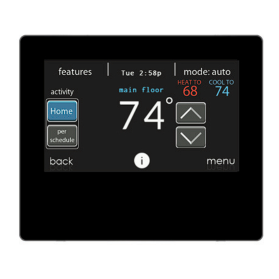
SYST0101CW
Ion™ System Control
NOTE: Read the entire instruction manual before starting the installation.
My Learning Center is your central location for professional residential HVAC training
resources that help strengthen careers and businesses. We believe in providing high quality
learning experiences both online and in the classroom.
NOTE: Please refer to the literature provided with the connected HVAC equipment for more
details on system operations with specific pieces of equipment.
The features and functions outlined in the Installation Instructions reflect Version 1 software.
See the Downloads section of the www.IonComfort.com website for the latest software release
and literature.
US Patents: U.S. Pat No. 7,243,004, U.S. Pat No. 7,775,452, pointSET™ U.S. Pat No.
7,415,102
Installation Instructions
™
A180023
Advertisement

Related Manuals for ION SYST0101CW


Summary of Contents for ION SYST0101CW
- Page 1 SYST0101CW Ion™ System Control ™ Installation Instructions A180023 NOTE: Read the entire instruction manual before starting the installation. My Learning Center is your central location for professional residential HVAC training resources that help strengthen careers and businesses. We believe in providing high quality learning experiences both online and in the classroom.
- Page 2 Table of Contents 1. Safety Considerations ..............5 2.
- Page 3 6.3.1.2. Heat/Cool Deadband ..........20 6.3.1.3.
- Page 4 6.4.1. Electric Heat ............. . 35 6.4.2.
- Page 5 Ion System Control (or User Interface), communicating variable speed furnace or FCM4 fan coil, single stage AC and HP, 2-stage AC and HP, and multi-stage AC and HP. The Ion System Control continually communicates with each ICP communicating HVAC unit via a four-wire connection called the communications bus.
- Page 6 Ion Communicating Relay Module or “CRM” (P/N SYST0101RM) may be required to provide additional control outputs. All system components are controlled through the wall mounted Ion System Control, which replaces the conventional thermostat and provides the homeowner with a single wall control for all features of the system.
- Page 7 • Touch the SERVICE icon for about 10 seconds, touch DEALER CONTACT INFORMATION, and then touch UPLOAD DEALER INFORMATION. • Place the micro SD card into the micro SD card slot on the bottom of the Ion System Control and follow the on screen prompts.
- Page 8 All wiring must comply with national, state, and local codes. 4.3.1. Wall Control The Ion System Control is the command center for the Ion System. It should be located where it is easily accessible and visible to the adult homeowner or end user. For accurate temperature...
- Page 9 4.3.2. Wired Remote Room Sensors A Remote Room Sensor can be used with the Ion System Control to take the place of the control’s internal temperature sensor. This allows the Ion System Control to be mounted in areas with less than optimal airflow (such as near an exterior door, window or in a closet). The remote sensor can be wired to the terminal block connectors labeled S1 and S2 at the control’s...
- Page 10 The shield wire should be connected to the C terminal, or ground, AT THE INDOOR UNIT, ONLY. The shield wire should NOT be connected to any terminal at the Ion System Control. Connecting the shield to ground at both ends can cause current loops in the shield, reducing shield effectiveness.
- Page 11 4.4.2. Damper Control Module (zoning systems only) When used, all wiring is run back to the Ion System Damper Control Module (SYST0101ZP). Select a location near the furnace or fan coil where wiring from the control, each Remote Room Sensor or Smart (Zone) Sensor (when available), each damper actuator, and the equipment itself can come together easily.
- Page 12 • Attach Ion System Control to the mounting plastic by lining up the plastic guides on the back of the control with the opening on the mounting plastic and push on.
- Page 13 Applying 24VAC isolation relay coil to furnace or fan coil HUM and COM terminals will allow the Ion System Control to automatically energize the HUM output during a call for humidification. The N.O.
- Page 14 5.2. Searching for Outdoor Unit NOTE: The Ion System Control will then proceed to communicate with the outdoor unit by displaying “Searching for outdoor unit”. If the outdoor unit cannot be found, the control will display “Outdoor unit not found”.
- Page 15 A13119 5.4.1. Hydronic Heat Application The Ion System Control supports two types of Hydronic Heat applications: 1. Hot water coil in combination with an FCM4 fan coil and heat pump, or hot water coil as sole heat source with an FCM4 fan coil.
- Page 16 A12185i 5.6. Filter Type Selection The installer will next be prompted to select the air filter type installed with the Ion System. After the selection is made, touch NEXT. • Air Filter: 1-in. to 4-in. media filter • EAC: high voltage electronic air cleaner •...
- Page 17 5.10. Airflow Verification Check NOTE: This feature is only available with specific ICP communicating indoor units. See the Ion System Control Product Data for compatible units and more information. The airflow verification check screen will appear next, as the system performs this operation.
- Page 18 If the Ion System Control detects an error (damper not moving or damper wired backwards), it will perform the duct assessment again. If it still detects a damper problem, it will default the measurements into equal sizes, with 10% leakage, and display the zone number for the suspected zone damper.
- Page 19 – Furnace – Fan coil • Outdoor: – AC/Heat pump Once the equipment has been selected, the appropriate menus will be displayed. 6.3.1. Thermostat First touch SETUP, then touch THERMOSTAT to set up the parameters for the Ion System Control.
- Page 20 NOTE: This feature is only available with specific ICP communicating indoor units. See the Ion System Control Product Data for compatible units and more information. • If Simultaneous Heat/Cool is turned ON, Auto changeover time is grayed out and shows N/A.
- Page 21 Offsets Section. When the correct offsets are made, touch SAVE. If the system is non-zoned, the indoor temperature offset is found on this screen. If the system is zoned, the indoor temperature offset is found in the Zoning, Offsets screen. •...
- Page 22 6.3.1.6. Smart Recovery On/Off NOTE: ”Smart Recovery” refers to transitions between and among the Home, Sleep and Wake modes. Moving from the Away mode to any other mode is covered by the “Smart Setback” feature. Smart Recovery applies to programmable operation only. Smart Recovery causes the system to ramp the system target setpoints to those for the next programmed schedule period to help save energy during period transitions.
- Page 23 NOTE: This feature is only available with specific ICP communicating indoor units. See the Ion System Control Product Data for compatible units and more information. 6.3.2.3. Dehumidification Options The Dehum Drain Time option turns off the continuous fan at the end of cooling for fifteen minutes in order to drain the indoor coil of water.
- Page 24 A13229 6.3.2.5. Fan Coil G-Terminal Alert Use the alert function to select the contact state for an alert. Select Normally Open or Normally Closed, and then save your selection. A13230 Shutdown: This setup option selects the change of state required for shutdown. Select Normally Open or Normally Closed, and then save your selection.
- Page 25 A14225A_2 6.3.3.1. Furnace Airflow Selects the airflow of the furnace when heating. EFFICIENCY is the airflow used to meet specified ratings, COMFORT is a decreased airflow used to increase the output air temperature and provide increased comfort. For the Low heat rise option, set to ON if the system contains a bypass humidifier. The ON setting will increase the furnace low heat airflow.
- Page 26 This option controls the staging of the furnace and selects the minimum amount of time low stage must operate before high stage is activated. SYSTEM setting will allow the Ion Zone Control to determine furnace staging. LOW will only run the low stage of furnace heat. HIGH will only run the high stage of furnace heat.
- Page 27 6.3.3.8. Furnace G Terminal This setup option selects desired operation when the R-G circuit changes state on the furnace control board depending on setup. Under the function option, FAN turns on fan to selected fan speed when G terminal is energized.
- Page 28 A170248 6.3.4. AC/Heat Pump First touch SETUP, then touch AC/HEAT PUMP to set up the parameters for the AC/Heat Pump unit. A14227A_2 6.3.4.1. Latching High Cool Latch A13227A • System in Control: The system will decide which stage should be running to satisfy the cooling demand.
- Page 29 Defrost. 6.3.4.4. Low Ambient Cooling See Ion System Control Product Data for compatible units and more information. Selecting YES will enable the low ambient cooling operation in the outdoor unit. This setting is only available with compatible communicating outdoor units and with Cooling Lockout set to NONE.
- Page 30 6.3.4.5. Quiet Shift This option turns on Quiet Shift function in 1-stage or 2-stage communicating heat pumps. After the selection is made, touch SAVE. NOTE: This option is not available with SmartSense heat pumps. • Quiet Shift: On or Off. Default = Off 6.3.4.6.
- Page 31 NOTE: This feature is only available with specific ICP communicating indoor units. See the Ion System Control Product Data for compatible units and more information. First touch SETUP, then touch ZONING to set up the parameters for the zoning system (if applicable).
- Page 32 • Disable Zoning: Yes or No. Default = No 6.3.7.2. Zone Offsets This option allows actual temperature offset for each zone, allowing calibration (or deliberate miscalibration) of each sensor. Use the Left (<) or Right (>) buttons to change the zone. After the selection is made, touch SAVE.
- Page 33 After the selections are made, touch SAVE. • Pressure Monitoring (not available or effective with air cleaners that do not use filter media, such as Electric Air Cleaners): Enable or Disable. See Ion System Control Product Data for compatible units and more information. Default = Enable •...
- Page 34 has a utility saver input (refer to outdoor equipment installation instructions). This setup controls the response of the equipment when the utility saver input is active. DISABLED means that the curtailment function is not active. TURN OFF means the outdoor unit is to be turned off when the curtailment function is active.
- Page 35 Before running Check Out mode, make sure that all HVAC equipment is properly installed. See the equipment installation instructions for details and additional safety information. See the Ion System Control Product Data for compatible units and more information. Touch CHECKOUT to view the equipment installed in the system. Perform checkout test to make sure each piece of equipment is operating properly.
- Page 36 • High Heat: Selectable from 0 to 120 minutes. Default = 5 minutes 6.4.3. Hydronic This option allows the hydronic heat relay to be exercised. First, it will energize the relay and turns on the blower. This sequence will be displayed on the screen. After the selections are made, touch START.
- Page 37 For SmartSense heat pumps, you can select the stage at which the heat pump will exercise. During the checkout, the stage and time can be changed by pressing the Change button on the checkout status screen. After the selections are made, touch START. NOTE: Airflows during Checkout modes are fixed to the EFFICIENCY setting and are independent of other airflow settings.
- Page 38 After proper damper operation has been verified, the installer can now check and verify that each Remote Room Sensor corresponds to the proper zone damper in the same zone. For systems with remote room sensor, temporarily disconnect any other zone Remote Room Sensor (at sensor location).
- Page 39 A12197 6.5.3. Furnace Status See the Ion System Control Product Data for compatible units and more information. The furnace status screen displays relevant information about the furnace operation. To return to the previous screen, touch BACK. To exit the Service menus, touch DONE.
- Page 40 6.5.6. Zoning Status NOTE: This feature is only available with specific ICP communicating indoor units. See the Ion System Control Product Data for compatible units and compatible units and more information. The zoning status screen displays relevant information about the zoning operation. To return to the previous screen, touch BACK.
- Page 41 A12151 6.5.8. Run/Fault History This information is stored in the equipment circuit boards (if communicating) and displayed on the control. The indoor unit and outdoor unit (if communicating) have the following histories. To return to the previous screen, touch BACK. To exit the Service menus, touch DONE. •...
- Page 42 A14231 6.6. Refrigerant Charging: SmartSense Systems This feature is only available on specific units. See the Ion System Control Product Data for compatible units and more information. For multi-stage heat pumps and AC units, a refrigerant charging menu is available to aid in the proper charging of the system. Enter the menu from the service screens by touching REFRIGERANT CHARGING.The option for HTG CHECK...
- Page 43 Next, the installer will enter the WEIGH IN screen to verify the current total charge is accurate. Once the installer has confirmed, touch DONE. Next, the installer will enter the SERVICE VALVE SUBCOOL screen. This screen will show the current liquid line subcool target (in °F). To begin the charging, touch START. If the outdoor temperatures are not in the required range, Service Valve Subcool may not be available.
- Page 44 • Set desired time period. Default time period for procedure is 120 minutes. • Touch START on Ion System Control or service tool to open the valve. • Begin evacuation or refrigerant recovery as required for the procedure after control indicates the EXV is open.
- Page 45 Once the dealer logo and contact information have been properly loaded onto the micro SD card, insert the micro SD card into the bottom edge of the Ion System Control. The control will prompt you whether or not to upload the dealer information. Once complete, you will receive a confirmation that your upload was successful.
- Page 46 Please call 1-877-591-8908 for support network with Wi-Fi network set-up and connection to the Ion Server. The ability to remotely access and adjust the settings of the Ion System Control with the Ion® Home mobile application is dependent on the compatibility of the user’s mobile device, the Ion System Control, and/or the Ion web server with, and the availability of the user’s mobile device...
- Page 47 7.1. Setup and Status Information (Homeowner’s Router) To establish Wi-Fi® connectivity to the Ion System Control using the in-home router or wireless access point, the wireless access point SSID and password/passkey must be known for set-up. A170241I • Select WIRELESS from the menu screen.
- Page 48 • After the control has connected to the network, go to www.IonComfort.com to register the unit or you can use the Ion® Home mobile app to begin remote access. This requires the MAC address and serial number of the Ion System Control. If using the Ion® Home mobile app you can just scan the QR Code on the wall control and it will fill in the control information.
- Page 49 • If you have any issues, please contact your servicing dealer or contact the support desk at 1-877-591-8908. • When the connection to the Ion web server has been established, the status screen will show Connected for both Wi-Fi and the server.
- Page 50 A180093...
- Page 51 8. Wiring Diagrams Variable-Speed Furnace/ Fan Coil Communicating AC, HP or GHP* User Interface Green - Data A Green Yellow - Data B Yellow White - COM White Red - 24VAC Optional Remote Room Sensor Communications Humidifier Connections Connection Sensor (Optional) *NOTE: Some outdoor units do not require the “C ”...
- Page 52 Variable-Speed Furnace/Fan Coil User Interface Green - Data A Yellow - Data B Communications White - COM Connection Red - 24VAC 1-Spd. Optional Remote Non-Communicating Room Sensor Humidifier Connection Y/Y2 Sensor A12354I Connection Diagram for Furnace or FCM4 Fan Coil with 1-Stage Air Conditioning...
- Page 53 Variable-Speed Fan Coil User Interface Green - Data A Yellow - Data B Communications White - COM Connection Red - 24VAC 1-Spd. Optional Remote Non-communicating Room Sensor Humidifier Connection Sensor A12355I Connection Diagram for FCM Fan Coil with Non-communication 1-Stage Heat Pump...
- Page 54 Indoor Communicating Unit AC or HP Zone Control User Interface & Smart Sensor(s) Green Yellow DX+ DX- White Humidifier Connection Damper Control module Sensor (Optional) A04018I Zoning Connection for Communicating Indoor Unit with 2-Stage Communicating Outdoor Unit NOTE: Some outdoor units do not require “C” and “R” connections. Please see outdoor unit Installation Instructions.
- Page 55 Indoor Unit Zone Control User Interface & Smart Sensor(s) Green Yellow White 1-Stage AC DX+ DX- DX+ DX- Humidifier Connection Damper Y/Y2 Control module Sensor A04019I Zoning Connection Diagram for ICP Communicating Furnace or FCM4 Fan Coil with Non-Communicating 1-Stage Air Conditioning...
- Page 56 Variable-Speed Zone Control Fan Coil User Interface & Smart Sensor(s) Green Yellow White 1-Spd. HP DX+ DX- Humidifier Connection Damper Control module Sensor A07149I Zoning Connection diagram for FCM4 Fan Coil with Non-communicating 1-Stage Heat Pump Non-comm ODU CRM required? Furnace 1-stage A/C Furnace...
- Page 57 A160171i Wiring Diagram Single-Stage Non-Communicating Heat Pump A160172i Wiring Diagram Two-Stage Non-Communicating Heat Pump CRM...
- Page 58 FCM4 Fan Coil or ICP Communicating Gas Furnace A07114i G Input Wiring for Blower Operation...
- Page 59 FCM4 Fan Coil or ICP Communicating Gas Furnace *NOTE: For gas furnaces, use the communicationbus “R” connection for best results. Using the thermostat “R” connection will cause an extraneous “G Input” alert when limit switches open. This is not normally a problem when using the normally open configuration on the previous page.
- Page 60 2) ce dispositif doit accepter toute interférence, y compris les interférences qui peuvent causer un mauvais fonctionnement de l’appareil. Ion and SmartSense are trademarks of International Comfort Products Corporation in the United States and other countries. Other brands and product names are trademarks of their respective holders.
- Page 64 © 2020 Carrier. All rights reserved. A Carrier Company Catalog No: 6160116003 997-018020-4-R 61601160002 Edition Date: 12/20 Replaces: Manufacturer reserves the right to change, at any time, specifications and designs without notice and without obligations.