Advertisement
Quick Links
SECTION 1 GENERAL
Group 1 Safety hints - - - - - - - - - - - - - - - - - - - - - - - - - - - - - - - - - - - - - - - - - - - - - - - - - - - - - - - - - - - - - - - - - - - - - - - - - - - - - - - - - - - - - - - - - - - - - - - - - - - - 1-1
Group 2 Specifications - - - - - - - - - - - - - - - - - - - - - - - - - - - - - - - - - - - - - - - - - - - - - - - - - - - - - - - - - - - - - - - - - - - - - - - - - - - - - - - - - - - - - - - - - - - - - - - - 1-5
Group 3 Periodic replacement - - - - - - - - - - - - - - - - - - - - - - - - - - - - - - - - - - - - - - - - - - - - - - - - - - - - - - - - - - - - - - - - - - - - - - - - - - - - - - - - - - - - - 1-13
SECTION 2 REMOVAL & INSTALLATION OF UNIT
Group 1 Major components - - - - - - - - - - - - - - - - - - - - - - - - - - - - - - - - - - - - - - - - - - - - - - - - - - - - - - - - - - - - - - - - - - - - - - - - - - - - - - - - - - - - - - - - 2-1
Group 2 Removal and Installation of Unit - - - - - - - - - - - - - - - - - - - - - - - - - - - - - - - - - - - - - - - - - - - - - - - - - - - - - - - - - - - - - - - - - - - 2-2
SECTION 3 POWER TRAIN SYSTEM
Group 1 Structure and operation - - - - - - - - - - - - - - - - - - - - - - - - - - - - - - - - - - - - - - - - - - - - - - - - - - - - - - - - - - - - - - - - - - - - - - - - - - - - - - - - - 3-1
Group 2 Troubleshooting - - - - - - - - - - - - - - - - - - - - - - - - - - - - - - - - - - - - - - - - - - - - - - - - - - - - - - - - - - - - - - - - - - - - - - - - - - - - - - - - - - - - - - - - - - - - - 3-3
Group 3 Disassembly and assembly - - - - - - - - - - - - - - - - - - - - - - - - - - - - - - - - - - - - - - - - - - - - - - - - - - - - - - - - - - - - - - - - - - - - - - - - - - 3-5
SECTION 4 BRAKE SYSTEM
Group 1 Structure and function - - - - - - - - - - - - - - - - - - - - - - - - - - - - - - - - - - - - - - - - - - - - - - - - - - - - - - - - - - - - - - - - - - - - - - - - - - - - - - - - - - - 4-1
SECTION 5 STEERING SYSTEM
Group 1 Structure and function - - - - - - - - - - - - - - - - - - - - - - - - - - - - - - - - - - - - - - - - - - - - - - - - - - - - - - - - - - - - - - - - - - - - - - - - - - - - - - - - - - - 5-1
SECTION 6 HYDRAULIC SYSTEM
Group 1 Structure and function - - - - - - - - - - - - - - - - - - - - - - - - - - - - - - - - - - - - - - - - - - - - - - - - - - - - - - - - - - - - - - - - - - - - - - - - - - - - - - - - - - - 6-1
Group 2 Operational checks and troubleshooting - - - - - - - - - - - - - - - - - - - - - - - - - - - - - - - - - - - - - - - - - - - - - - - - - - - - - - - 6-9
Group 3 Disassembly and assembly - - - - - - - - - - - - - - - - - - - - - - - - - - - - - - - - - - - - - - - - - - - - - - - - - - - - - - - - - - - - - - - - - - - - - - - - - - - 6-13
SECTION 7 ELECTRICAL SYSTEM
Group 1 Component location - - - - - - - - - - - - - - - - - - - - - - - - - - - - - - - - - - - - - - - - - - - - - - - - - - - - - - - - - - - - - - - - - - - - - - - - - - - - - - - - - - - - - - 7-1
Group 2 Electrical circuit - - - - - - - - - - - - - - - - - - - - - - - - - - - - - - - - - - - - - - - - - - - - - - - - - - - - - - - - - - - - - - - - - - - - - - - - - - - - - - - - - - - - - - - - - - - - - - 7-2
Group 3 Electric components - - - - - - - - - - - - - - - - - - - - - - - - - - - - - - - - - - - - - - - - - - - - - - - - - - - - - - - - - - - - - - - - - - - - - - - - - - - - - - - - - - - - - - 7-3
SECTION 8 MAST
Group 1 Structure - - - - - - - - - - - - - - - - - - - - - - - - - - - - - - - - - - - - - - - - - - - - - - - - - - - - - - - - - - - - - - - - - - - - - - - - - - - - - - - - - - - - - - - - - - - - - - - - - - - - - - - - 8-1
Group 2 Operational checks and troubleshooting - - - - - - - - - - - - - - - - - - - - - - - - - - - - - - - - - - - - - - - - - - - - - - - - - - - - - - - 8-3
Group 3 Adjustment - - - - - - - - - - - - - - - - - - - - - - - - - - - - - - - - - - - - - - - - - - - - - - - - - - - - - - - - - - - - - - - - - - - - - - - - - - - - - - - - - - - - - - - - - - - - - - - - - - - - - 8-6
Group 4 Removal and installation - - - - - - - - - - - - - - - - - - - - - - - - - - - - - - - - - - - - - - - - - - - - - - - - - - - - - - - - - - - - - - - - - - - - - - - - - - - - - - - - 8-9
CONTENTS
Advertisement

Related Manuals for Hyundai 10BOP-7


Summary of Contents for Hyundai 10BOP-7
- Page 1 CONTENTS SECTION 1 GENERAL Group 1 Safety hints - - - - - - - - - - - - - - - - - - - - - - - - - - - - - - - - - - - - - - - - - - - - - - - - - - - - - - - - - - - - - - - - - - - - - - - - - - - - - - - - - - - - - - - - - - - - - - - - - - - - 1-1 Group 2 Specifications - - - - - - - - - - - - - - - - - - - - - - - - - - - - - - - - - - - - - - - - - - - - - - - - - - - - - - - - - - - - - - - - - - - - - - - - - - - - - - - - - - - - - - - - - - - - - - - - 1-5 Group 3 Periodic replacement - - - - - - - - - - - - - - - - - - - - - - - - - - - - - - - - - - - - - - - - - - - - - - - - - - - - - - - - - - - - - - - - - - - - - - - - - - - - - - - - - - - - - 1-13 SECTION 2 REMOVAL &...
- Page 2 SECTION 8 MAST This section explains the structure of mast, carriage, backrest and forks. The specifications contained in this service manual are subject to change at any time and without any advance notice. Contact your HYUNDAI distributor for the latest information.
- Page 3 When a manual is revised, an edition mark is Any additions, amendments or other changes will recorded on the bottom outside corner of the be sent to HYUNDAI distributors. pages. Get the most up-to-date information before you start any work.
- Page 4 3. CONVERSION TABLE Method of using the Conversion Table The Conversion Table in this section is provided to enable simple conversion of figures. For details of the method of using the Conversion Table, see the example given below. Example Method of using the Conversion Table to convert from millimeters to inches Convert 55mm into inches.
- Page 5 Millimeters to inches 1mm = 0.03937in 0.039 0.079 0.118 0.157 0.197 0.236 0.276 0.315 0.354 0.394 0.433 0.472 0.512 0.551 0.591 0.630 0.669 0.709 0.748 0.787 0.827 0.866 0.906 0.945 0.984 1.024 1.063 1.102 1.142 1.181 1.220 1.260 1.299 1.339 1.378 1.417 1.457...
- Page 6 Liter to U.S. Gallon = 0.2642 U.S.Gal 0.264 0.528 0.793 1.057 1.321 1.585 1.849 2.113 2.378 2.642 2.906 3.170 3.434 3.698 3.963 4.227 4.491 4.755 5.019 5.283 5.548 5.812 6.6076 6.340 6.604 6.869 7.133 7.397 7.661 7.925 8.189 8.454 8.718 8.982 9.246 9.510...
- Page 7 m to lbf ft 1kgf m = 7.233lbf ft 14.5 21.7 28.9 36.2 43.4 50.6 57.9 65.1 72.3 79.6 86.8 94.0 101.3 108.5 115.7 123.0 130.2 137.4 144.7 151.9 159.1 166.4 173.6 180.8 188.1 195.3 202.5 209.8 217.0 224.2 231.5 238.7 245.9 253.2...
- Page 8 kgf/cm to lbf/in 1kgf / cm = 14.2233lbf / in 14.2 28.4 42.7 56.9 71.1 85.3 99.6 113.8 128.0 142.2 156.5 170.7 184.9 199.1 213.4 227.6 241.8 256.0 270.2 284.5 298.7 312.9 327.1 341.4 355.6 369.8 384.0 398.3 412.5 426.7 440.9 455.1 469.4...
- Page 9 TEMPERATURE Fahrenheit-Centigrade Conversion. A simple way to convert a fahrenheit temperature reading into a centigrade temperature reading or vice verse is to enter the accompanying table in the center or boldface column of figures. These figures refer to the temperature in either Fahrenheit or Centigrade degrees. If it is desired to convert from Fahrenheit to Centigrade degrees, consider the center column as a table of Fahrenheit temperatures and read the corresponding Centigrade temperature in the column at the left.
- Page 10 SECTION 1 GENERAL SECTION 1 GENERAL Group 1 Safety hints --------------------------------------------------------------------------------------------------------- Group 2 Specifications ----------------------------------------------------------------------------------------------------- Group 3 Periodic replacement ----------------------------------------------------------------------------------------- 1-13...
- Page 11 GROUP 1 SAFETY HINTS Careless performing of the easy work may cause injuries. Take care to always perform work safely, at least observing the following. Oil is a dangerous substance. Never handle oil, grease or oily clothes in places where there is any fire of flame.
- Page 12 Hand a caution sign in the operator's compartment (For example Do not start or Maintenance in progress). This will prevent anyone from starting or moving the machine by mistake. D50ASF07 When inspecting running parts or near such parts, always stop the machine first. Before checking or servicing accumulator or piping, depress brake pedal repeatedly to release pressure.
- Page 13 Unless you have special instructions to the contrary, maintenance should always be carried out with the machine stopped. maintenance is carried out with the machine running, there must be two men present : one sitting in the operator's seat and the other one performing the maintenance.
- Page 14 Way to use dipstick Push the dipstick fully into the guide, and then pull out. Carrying out other difficult maintenance work carelessly can cause unexpected accidents. If you consider the maintenance is too difficult, always request the HYUNDAI Forklift distributor to carry out...
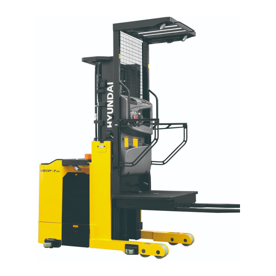
- Page 15 GROUP 2 SPECIFICATIONS 1. GENERAL LOCATIONS 10BOP7OM51 Mast Steering wheel Fork and platform Overhead guard Load tire Guide roller Drive unit and tire...
- Page 16 2. SPECIFICATIONS 10/13BOP-7 H2 H1 H3 H4 W3 W2 10BOP7SP01 Model Unit 10BOP-7 13BOP-7 Capacity 1000 1360 Load center Weight 2691 2831 Max lifting height 3275 Min lifting height Fork Max spread width Dimensions (T W L) 100 1200 3440...
- Page 17 3. SPECIFICATION FOR MAJOR COMPONENTS CONTROLLER Item Unit Traction motor Pump motor Eps motor Nominal battery voltage 350/3 45/2 Maximum output current 180/2 0~200 Output frequency range Dimensions (L W H) 200 150 105 200 150 120 144 180 64.8 Weight 0.72 2 2 )
- Page 18 B B RAKES Item Unit Specification Type Electromagnetic brake BATTERY Dimensions Voltage Capacity Weight Length (L) Width (W) Height (H) Model 38.3 14.4 31.1 10BOP-7 38.3 14.4 31.1 725 35 38.3 16.3 31.1 730 35 13BOP-7 38.3 16.3 31.1 830 40...
- Page 19 4. TIGHTENING TORQUE FOR MAJOR COMPONENTS 10/13BOP-7 Items Size kgf m lbf ft Hyd pump motor mounting bolt Electric system Traction motor mounting bolt 4.1 0.4 29.7 2.9 M 8 1.25 Hydraulic pump mounting bolt M10 1.5 Hydraulic MCV mounting bolt, nut 6.9 1.4 50 10 M10 1.5...
- Page 20 5. TORQUE CHART Use following table for unspecified torque. BOLT AND NUT - Coarse thread Bolt size kgf m lbf ft kgf m lbf ft 0.85 ~ 1.25 6.15 ~ 9.04 1.14 ~ 1.74 8.2 ~ 12.6 1.25 2.0 ~ 3.0 14.5 ~ 21.7 2.7 ~ 4.1 19.5 ~ 29.7...
- Page 21 PIPE AND HOSE(FLARE TYPE) Thread size(PF) Width across flat kgf m lbf ft 1/4" 28.9 3/8" 36.2 1/2" 68.7 3/4" 130.2 1" 151.9 1-1/4" 253.2 IPE AND HOSE(ORFS TYPE) Thread size(UNF) Width across flat mm kgf m lbf ft 9/16-18 28.9 11/16-16 36.2...
- Page 22 6. RECOMMENDED LUBRICANTS Use only oils listed below or equivalent. Do not mix different brand oil. Ambient temperature C( F) Service Kind of Capacity (U.S. gal point fluid (-31) (-4) (14) (32) (50) (68) (86) (104) Drive Gear oil SAE 80W/90 unit (0.58) ISO VG 22...
- Page 23 GROUP 3 PERIODIC REPLACEMENT For operation safety, never fail to perform periodic maintenance or make periodic replacement of the consumable parts listed in the following. These parts may deteriorate in time and are susceptible to wear. It is difficult to estimate the degree of wear at time of periodic maintenance;...
- Page 24 SECTION 2 REMOVAL AND INSTALLATION OF UNIT SECTION 2 REMOVAL AND INSTALLATION OF UNIT Group 1 Major components------------------------------------------------------------------------------------------ 2-1 Group 2 Removal and installation of unit --------------------------------------------------------------------- 2-2...
- Page 25 SECTION 2 REMOVAL & INSTALLATION OF UNIT GROUP 1 MAJOR COMPONENTS 7 8 6 10BOP7OM61 Display Beacon lamp Start switch 10 Emergency switch Multifunction lever 11 Dead man switch Head lamp 12 Pallet clamp Fan switch 13 Pallet clamp pedal Work lamp switch 14 Pallet clamp release pedal Beacon switch...
- Page 26 GROUP 2 REMOVAL AND INSTALLATION OF UNIT Remove and install following units as explained in the flow chart. 1. MAST REMOVAL Platform & Piping Fork Mast overhead guard PREPARATION Lift up the platform from the floor to easy removal of the forks. Prop up blocks under the platform in order that it can avoid from unintentional lowering of the platform.
- Page 27 FORKS Loosen and remove bolts(2), washers(3) and shims(4) which are used for fixing the forks(5) under the platform(1). Loosen bolts(7), and then remove pins(6) which are used for fixing the forks(8) to the platform(1). 10BOP7RE03 MAST & PLATFORM REMOVAL Remove bolts and retainer plates from the left and right sides of truck frame.
- Page 28 PLATFORM While slacking the lift chains(4), loosen and remove split pin(1), nuts(2) from anchor bolt(3) of the chains(4). 10BOP7RE06 Pull the chains out of the sheaves and drape them over the front of carriage. Chain Carriage 10BOP7RE07...
- Page 29 PIPING Remove the return hoses and clamps attached to the cylinder. Remove the return hoses from the connector. Remove hose assembly, connector, down safety valve from the lift cylinder. Disconnect hose assembly from the flow regulator. Outer mast Inner mast Middle mast Lift...
- Page 30 INNER MAST Using an overhead hoist raise the inner mast straight and carefully draw out of Free lift cylinder outer mast section. Be careful the mast not to swing or fall. Inner Using an universal puller, remove the mast load rollers. Middle mast Outer...
- Page 31 NSTALLATION After assembling mast components totally without piping connections, install mast assembly to the equipment. Installation procedure for each of mast component is the reverse of the removal procedure. LIFT CYLINDER INSTALLATION AND ADJUSTMENT Assemble the lift cylinder inside the outer mast, then tighten the stopper bolt.
- Page 32 2. POWER TRAIN ASSEMBLY REMOVAL Battery cable Side door BRJ7RE001 Disconnect the battery cable. PUMP INVERTER Battery cable connector TRACTION INVERTER LINE CONTACTOR 10BOP7OM121 After loosening the bolts of the hinges, remove the side door. Side door 10BOP7RE21 Disconnect the hose, pipe and wiring from pump &...
- Page 33 Disconnect the wiring . Drive motor wiring EPS motor wiring Loosen mounting bolts for the drive unit Drive motor assembly. Mounting bolt EPS motor 10BOP7RE23 Lift up the frame and support both side of frame with wood block. Jack up Wood block 10BOP7RE24 Hang up the drive unit assembly using...
- Page 34 INSTALLATION Installation is in the reverse order to removal, but be careful of following points. Drive unit mounting bolts : 6EA Drive motor Tightening torque : 13.2~16.2kgf m Mounting (95.5~117.1lbf ft) bolt Drive unit bracket mounting bolt : 6EA EPS motor Tightening torque : 13.2~16.2kgf m (95.5~117.1lbf ft) 10BOP7RE23...
- Page 35 3. ELECTRICAL COMPONENTS Before removing each component, disconnect cables and earth lines attached to the component. REMOVAL Side door Battery assembly 10BOP7RE002 PUMP MOTOR PUMP INVERTER Disconnect the battery cable. Battery cable connector TRACTION INVERTER LINE CONTACTOR 10BOP7OM121 After loosening the bolts of the hinges, remove the side door.
- Page 36 Disconnect the hoses, pipes and wiring Pump motor from pump & motor assembly. mounting bolt Wiring Loosen mounting bolts from frame and Pump motor then take out the pump & motor assembly Pump motor assembly. mounting bolt Pump Hose Pump mounting bolt 10BOP7RE26 DRIVE MOTOR...
- Page 37 Remove bolts to fix the motor and drive unit. Mounting bolt Mounting bolt BRP7RE22 Tie wire rope around the drive motor and lift up slowly. Drive motor Drive unit BRP7RE23 Put the motor on the clean work bench. BRP7RE24 2-13...
- Page 38 EPS MOTOR PUMP INVERTER Disconnect the battery cable. Battery cable connector TRACTION INVERTER LINE CONTACTOR 10BOP7OM121 After loosening the bolts of the hinges, remove the side door. Side door 10BOP7RE21 Disconnect wirings. motor 10BOP7RE28 Loosen bolts and remove EPS motor assembly.
- Page 39 BATTERY REMOVAL PUMP INVERTER Turn off the key. Battery cable Release the lock screw of side support in connector frame. Disconnect the battery connector. TRACTION INVERTER Pull out the battery and using a battery hanger, carefully raise the battery LINE CONTACTOR assembly.
- Page 40 INSTALLATION Installation is in the reverse order to removal, but be careful of following points. PUMP MOTOR Pump motor Pump motor mounting bolts : 4EA mounting bolt Tightening torque : 6.5kgf m Wiring Pump motor (47lbf ft) assembly Hydraulic pump mounting bolts : 2EA Pump motor mounting bolt Tightening torque : 5kgf m...
- Page 41 BATTERY INSTALLATION Using a battery hanger, carefully push in the battery assembly in the battery assembly compartment. Adjust the lock screw of side support in frame. Connect the battery connector. 10BOP7OM122 PUMP INVERTER Battery cable connector TRACTION INVERTER LINE CONTACTOR 10BOP7OM87 2-17...
- Page 42 4. TIRE & WHEEL ASSEMBLY REMOVAL DRIVE TIRE & WHEEL ASSEMBLY Lift up lower side of the frame and put on the wooden blocks under the both side of the frame. Jack up Lift up until the tire clear off the ground.
- Page 43 INSTALLATION Installation is in the reverse order to removal, but be careful of the following points. Drive wheel nuts Tightening torque : 13.5~15.5kgf m (98~112lbf ft) Wheel nut 10BOP7RE31 When assembling bearings in the leg Retaining assembly, it should be cleaned on the pin ring and in the bore of the load tire assy in order to prevent it from scratch or damage.
- Page 44 FRONT GUIDE ROLLER Lift up and prop up with wooden block under guide roller bracket. Remove split pin(1), washers(2) and clevis pin(3) from front bracket assy(4). Take out front roller assy which are assembled with guide wheel(5), ball bearings(6) shaft (7), washers(9) and retaining rings(8) pior to disassembling, and then remove the spring (10) from the bracket assy (4).
- Page 45 REAR GUIDE ROLLER Loosen and remove bolts(1) from leg assy(7) of the frame. After taking out rear guide roller assy, remove retaining rings(2) shafts(3), washers(4) and guide rollers(5) including ball bearing(6). After checking condition of the guide wheels and ball bearings, replace it if necessary.
- Page 46 SECTION 3 POWER TRAIN SYSTEM SECTION 3 POWER TRAIN SYSTEM Group 1 Structure and operation --------------------------------------------------------------------------------- 3-1 Group 2 Troubleshooting ---------------------------------------------------------------------------------------------- 3-3 Group 3 Disassembly and assembly --------------------------------------------------------------------------- 3-5...
- Page 47 SECTION 3 POWER TRAIN SYSTEM GROUP 1 STRUCTURE AND OPERATION 1. DRIVE UNIT STRUCTURE 10/13BOP-7 BRJ7DU101 Hexagon screw 14 Slotted pin 27 Protection cap Turntable bearing 15 Retaining ring 28 Bearing ball Steering gear 16 Taper roller bearing 29 Housing Breather valve 17 Shim 30 Shim...
- Page 48 2. SPECIFICATION Item Unit Specification Gear ratio Total 14.5 Oil Quantity...
- Page 49 GROUP 2 TROUBLESHOOTING Problem Cause Remedy 1. Noise 1) Loud, beating noise Check tooth flanks of the drive pinion Gearing of helical gear stage damag- and the helical gear for damage. In ed, indentations. case of damage always replace both components.
- Page 50 Fault Probable cause Remedy Oil leakage on oil filler or oil Dirt between sealing ring and Cleaning required. drain plug housing. Old sealing ring was used. Use new sealing ring Bolts not tightened according to the Tighten bolts with the specified specified tightening torque.
- Page 51 GROUP 3 DISASSEMBLY AND ASSEMBLY INSTRUCTION Pay attention to cleanliness and expert like manner for all work to be carried out. Transmission removed from the vehicle has therefore to be cleaned prior to opening. Both utmost care and cleanliness are essential conditions for a correct disassembly and reassembly of the transmission as well as for the installation of each spare part.
- Page 52 NECESSARY SPECIAL TOOLS FOR DISASSEMBLY AND REASSEMBLY Reference number Description Is necessary for : 225296 Extracting fixture Removal of drive pinion 62519 Holding fixture Loosening of taper press fit 62507-1 Counter holder Determination of shim thickness 62523 Assembly fixture Installation of drive pinion 62478 Striking mandrel Roller bearing drive pinion...
- Page 53 Modifications and changes without the proper permission are affecting the safety of the transmission and are not allowed. Only original spare parts from Hyundai are allowed to be used. It is explicitly pointed out to the fact that spare parts and accessories, which were not supplied by Hyundai are not checked and approved by us either.
- Page 54 4. COMPLETE DISASSEMBLY GENERAL INSTRUCTIONS DISASSEMBLY Prior to dismantling the transmission is to be cleaned carefully. Parts which are only available as assemblies will not be dismantled further. It is recommendable to install a locating fixture as shown in Figure 44. It serves to rotate the unit and offers easy working for disassembly and BRJ7DU044...
- Page 55 REMOVAL OF DRIVE PINION With a screwdriver press the radial sealing ring (item 2) upwards from the bore seat of the housing and remove it. Dispose of the radial sealing ring according to chapter 6. BRJ7DU045 Unsnap and remove the retaining ring (item 3) from the housing bore by means of flat-head pliers.
- Page 56 Handle the extracting fixture "S" as shown on the right. Move the handle on the bar upwards strongly several times until the drive pinion is loosened from the bearing seat completely. Do not damage the gearing of the drive pinion at the next work step! Damages might cause louder running noises and consequential damages! BRJ7DU049...
- Page 57 REMOVAL OF GEAR RING AND PIVOTED BOGIE BEARING Loosen the 12 hexagon screws (item 1) on the pivoted bogie bearing (item 2), remove and dispose them of acc. to chapter 6. BRJ7DU053 With a dead-blow soft-face hammer slightly beat against the gear ring (item 3) from the bottom to loosen it from the connecting construction.
- Page 58 DISASSEMBLY OF TRANSMISSION HOUSING WITH TRANSMISSION COMPONENTS Removal of sealing cap The surface (item 1) where the sealing cap is located must not be damaged. The sealing cap itself is destroyed and cannot be reused. Insert a screwdriver (item 2) into the sealing cap (item 3) beating cautiously and press it off or by using the lever effect upwards and scrap it.
- Page 59 Loosen the housing cover (item 2) by tapping against the outer edges and remove it. Use the two recesses in the housing. BRJ7DU059 With a three-armed puller (item 4) pull the taper roller bearing inner ring (item 3) over the bearing seat of the wheel shaft and remove it.
- Page 60 Loosening of taper press fit For work at high oil pressures to loosen the taper press fit there is the danger of eye and skin injuries, if oil would come out under high pressure. Always wear goggles and safety gloves! Observe and follow the instructions of the pressure oil device manufacturer. A pressure oil device with a maximum pressure of up to 300 MPa is necessary for widening of the taper press fit.
- Page 61 Connect the flexible high-pressure pipe (item 4) from the pressure oil device into the connecting bore provided in the wheel shaft (item 5). Fixedly tighten the connecting nipple with an openjaw spanner. Pay attention for pressing-off that there is sufficient clearance in pressing-off direction avoiding that the wheel shaft BRJ7DU065 is bottoming.
- Page 62 Loosen the cap screws (item 10), take off and remove the holding fixture "S" from the housing. BRJ7DU069 Pressing-off by means of 2nd hand pump Alternatively the wheel shaft can be pressed off with a second press-out cylinder, e.g. in the mobile area. It is to be proceeded as follows: Connect the dis- and assembly fixture with the press-out cylinder for the wheel...
- Page 63 Take the wheel shaft out of the transmission. BRJ7DU073 Unscrew the hydraulic hose from cylinder 1 of the wheel shaft. Wipe off excessive oil. BRJ7DU074 Unscrew the dis- and assembly fixture from the transmission When the gearing is damaged, running noises and consequential damages might occur, so that the bevel gear set has to be replaced.
- Page 64 Then remove the following parts from the housing (item 12) : Shims and taper roller bearing BRJ7DU077 Removal of bevel pinion shaft Put the gear lock "S" into the housing bearing bore of the drive pinion and block the helical gear with it. (S) Gear lock 62228 BRJ7DU078 Unlock the hexagon nut (item 1).
- Page 65 Pull out, remove and keep the helical gear (item 3) from the cover opening of the housing. BRJ7DU081 Take out and remove the taper roller bearing inner ring (item 4) upwards from the bearing bore: BRJ7DU082 Take off and remove the spacer bush (item 5) from the bevel pinion shaft.
- Page 66 Removal of thread protective shield and radial sealing ring By means of a hammer remove the thread protective shield (item 1) from the glued joint on the housing. Do not damage the housing and supporting face! BRJ7DU085 With a screwdriver and a hammer expel and remove the radial sealing ring (item 2) cautiously from the housing seat.
- Page 67 isassembly bearings bevel pinion shaft Expel the outer rings of the taper roller bearings (item 2) on both sides from the housing seat cautiously. Shims which were damaged have to be replaced by new shims of the same size. BRJ7DU088 Disassembly bearings wheel shaft Expel the outer ring of the taper roller bearing (item 3) by means of a copper...
- Page 68 5. COMPLETE REASSEMBLY GENERAL INSTRUCTIONS FOR REASSEMBLY Clean components by means of cleaning agent if necessary and remove the loctite residues. Check all components for wear, damage and cracks, if necessary components have to be replaced. All connection faces and plan face clean and steadily smoothing. CONSUMABLES Suitable cold cleaners, e.g.
- Page 69 USE OF REMOVED SHIMS AS BASIS FOR REASSEMBLY The bevel gear set, consisting of bevel pinion shaft and crown gear, has fixed installation dimensions. However the transmission housing and the taper roller bearings have to be measured. If the removed shims are used as basis it is not necessary to measure the transmission housing. If all of the removed components are to be reused, the original shim thickness has also to be used again.
- Page 70 DETERMINATION OF BEARING WIDTH DIFFERENCE OF A TAPER ROLLER BEARING Determination of bearing width general Zeroize depth gauge (item 1) by means of gauge blocks (item 2). BRJ7DU091 Put the new bearing on both gauge blocks and roll it as shown. BRJ7DU092 Determine dimension "B".
- Page 71 DETERMINATION OF BASIC INSTALLATION DIMENSIONS Determination of the necessary shim thickness for the exact installation dimension setting of the bevel pinion shaft The correct position of the bevel pinion shaft is required for an optimum service life of the transmission. Thickness of the shim (Item 1) and the correct setting of the bevel pinion shaft respectively will be determined according to the following method: Put measuring fixture I Part...
- Page 72 BRJ7DU096 BRJ7DU095 BRJ7DU097 At zero position of the dial gauge the following can be taken as basis: Dimension "1" = 111.50 mm Determine Dimension "2" in housing bearing bore L3 (see figure 94) and add it to the respective Dimension "1". Example : Dimension "1"...
- Page 73 Determination of necessary shim thickness for optimum setting of torsional backlash of the crown gear Correct setting of the crown gear is necessary to obtain an optimum torsional backlash of the bevel gearing. Bearing width "B" for the taper roller bearing on the crown gear can be measured according to chapter 5) at page 3-24 "Determination of bearing width and difference of a taper roller bearing".
- Page 74 By means of the equation Schematic sketch X = G - E - B - K1 the required thickness of the shim (Item 3) can be calculated, i.e. with Dimension "E" = 46.00 mm Example : Dimension "G" 68.53 mm Dimension "B"...
- Page 75 INSTALLATION OF BEARING FOR BEVEL PINION SHAFT AND EXACT SETTING OF THE BEARING PRELOAD Preassembly of bevel pinion shaft with bearing Use a hand-lever press for pressing the taper roller bearing inner ring (item 1) with the press-in sleeve "S" cautiously on the bevel pinion shaft (item 2) until contact is obtained.
- Page 76 Calculation of distance dimension between collar bevel pinion shaft and housing Install the preassembled bevel pinion shaft (item 1) from the bottom into the housing. BRJ7DU105 By means of the counter holder "S" preload the bearing outer ring in the housing hand-tight.
- Page 77 Determine distance dimension "D" from the spacer bush (item 2) to contact of the bearing outer ring in the housing. (item 3 is the required shim thickness) BRJ7DU108 Determination of bearing slack of the taper roller bearing Arrow gap = Bearing slack H BRJ7DU110 3-31...
- Page 78 Measure the bearing slack "H" with a measuring fixture gauge blocks/measuring ledge in the following steps : Zeroizing of depth gauge (item 1) by means of gauge blocks (item 2). BRJ7DU111 Rolling-in of bearing. BRJ7DU112 Measuring of bearing slack H. Example : Dimension "H"...
- Page 79 Calculation of shims required for upper bevel pinion shaft bearing By means of the equation X = D - H the required thickness of the shim (Item 3 figure 108 or 109) can be calculated, i.e. with Dimension "D" Distance from spacer bush Dimension "H"...
- Page 80 Put the bearing inner ring (item 3) into the outer ring of the taper roller bearing. BRJ7DU116 Installation of grooved ball bearing for drive pinion Install the grooved ball bearing (item 1) with the striking mandrel "S" into the bearing seat of the housing until contact is obtained.
- Page 81 Install the bevel pinion with space bush (item3) from the bottom into the housing and assemble is through the profiled seat of the helical gear bore. BRJ7DU123 Preload the bevel pinion shaft (item 3) with the counter holder "S" hand-tight against the bearing outer rings in the housing.
- Page 82 Place the hexagon nut (M16 1.5) onto the bevel pinion shaft and tighten it with a torque spanner (item 4). Tightening torque : 100 Nm Do not yet peen the hexagon nut with the bevel pinion shaft! The hexagon nut must only be peened after setting and checking of the bearing preload.
- Page 83 INSTALLATION OF CROWN GEAR AND WHEEL SHAFT INTO THE HOUSING Installation of thread protective shield and radial sealing ring Wet the thread protective shield (item1) on the bore seat evenly with LOCTITE 270 and install it until contact by means of the striking mandrel "S".
- Page 84 nstallation of taper roller bearing into the housing By means of striking mandrel "S" drive the bearing outer ring into the bearing seat of the housing until contact is obtained. (S) Striking mandrel 62542 BRJ7DU132 Insert the bearing inner ring (item 1) into the outer ring of the taper roller bearing.
- Page 85 Pay attention not to damage the gearing, when the crown gear is assembled. BRJ7DU135 Assemble the crown gear (item 4) into the housing carefully and insert it into the gearing of the bevel pinion shaft at the same time. Pay attention that the crown gear is aligned centrally to the shim and the bush.
- Page 86 Pressing-on wheel shaft Taper press fit must be grease- and oilfree. Pay attention to an impeccable surface of the press fit. In case of damage use a new wheel shaft. All components must be aligned and centered for the press-on procedure. For this installation procedure a press with a controllable press-on force is required.
- Page 87 Determination of seat The seat must be 10 to 15 mm. Measure Dimension A from plane face/wheel shaft to face/crown gear once again (see chapter 9) (3) at page 3-38 "Determination of control dimension for seat“). Dimension "A" e.g. 44.34 mm BRJ7DU140 Example: Dimension "A"...
- Page 88 INSTALLATION OF BEARING FOR WHEEL SHAFT Determination of required shim thickness for exact bearing preload of the wheel shaft Thickness of the shim (item 4) to be added can be determined with the following method: BRJ7DU142 Measuring ledge Housing cover Dim.
- Page 89 Calculation of shim required Thickness of shim can be calculated with the dimensions determined. Example : Cover dimension : Dim. C measured on housing cover 0.85 mm Housing dimension : Dim. F measured on housing 23.01 mm Bearing dimension : Dim. B measured on bearing under preloading force 21.85 mm X1 = F - (C + B) X1 = 23.01 - (0.85 + 21.85) = 0.31 mm...
- Page 90 Place counter holder "N" into the assembly fixture and preload it hand-tight against the wheel shaft (cf. figure 124). (N) Counter holder 62507-1 Mount the taper roller bearing inner ring (item 2) by means of striking mandrel "S" onto the bearing seat of the wheel shaft (item 3) until contact is obtained.
- Page 91 Checking of bearing friction torque on wheel shaft Rolling For measuring of the bearing friction torque place tool "S" on the wheel shaft congruent with the wheel bolts and by means of the torque spanner turn the wheel shaft several times. (S) : Measuring fixture 62532 BRJ7DU150 Bearing preload is adjusted correctly when a bearing friction torque of is obtained at the wheel...
- Page 92 Installation of side cover Prior to the installation of the side cover clean the sealing surface on the housing and remove the oil residues. The sealing surface must not be damaged. Wear safety gloves for working with adhesives and observe the LOCTITE instructions. The following step must be carried out within 10 minutes since the LOCTITE hardens.
- Page 93 Do not yet tighten the cap screws with the corresponding tightening torque. Tighten the 10 cap screws evenly only in the tightening sequence shown in Figure 156. Sequence of tightening : Number 1 beginning ..Number 10 end Tightening torque of the cap screws : 9.5 Nm BRJ7DU156 REASSEMBLY AND INSTALLATION OF DRIVE PINION Installation of ball bearing...
- Page 94 Mounting of sealing cap For sealing of the bore in the drive pinion a sealing cap (item 5) must be mounted. This requires the following sealing application: LOCTITE 5910 : Product application as adhesive application onto the supporting BRJ7DU158 face and around the bore in the drive pinion as sealing function by excessive product.
- Page 95 Snap the retaining ring (item 2) by means of flat-head pliers into the groove of the housing bore and install it until contact is obtained. BRJ7DU162 Wet the sealing lip of the radial sealing ring with grease (e.g. Shell Alvania R3) slightly.
- Page 96 Attachment of pivoted connection geared steering Place the gear ring (item 2) and turn it so that the bolt holes match the threaded holes of the connecting construction. Install the gear ring with a dead-blow soft face hammer until contact is obtained. BRJ7DU166 Put on the pivoted bogie bearing (item 3) with the peripheral recess upwards and...
- Page 97 6. DISPOSAL Disposal of the replaced components, materials and substances adequately, environmentally friendly and in accordance with the legal regulations for disposal for the respective material : Component Consisting of Disposal acc. to the regulations : Transmission oil Waste oil Side cover Sheet Radial sealing ring...
- Page 98 SECTION 4 BRAKE SYSTEM SECTION 4 BRAKE SYSTEM Group 1 Structure and function ------------------------------------------------------------------------------------ 4-1...
- Page 99 SECTION 4 BRAKE SYSTEM GROUP 1 STRUCTURE AND FUNCTION 1. STRUCTURE 10BOP7EB01 Inductor Flange Friction disc Screw Adjusting spacer 2. SPECIFICATION Description Unit Specification Nominal torque(Standard version) Nominal airgap(S+0.1/-0.5) 0.35 9.1(M6 on 132mm) Nominal torque 22(M8 on 145mm) 9.1(M6 on 168mm)
- Page 100 Any modification made to the brake without the express authorization of representative of Hyundai, in the same way than any use out of the contractual specifications accepted by Hyundai, will result in the warranty being invalidated and Hyundai will no longer be liable in any way with regard to conformity.
- Page 101 5. REASSEMBLY AND INSTALLATION PK brakes are delivered completely assembled. Put the key into the shaft then slide the hub (#3) onto the shaft and secure it axially by suitable means. Slide the brake onto the hub (#3), taking care not to damage the splines of the disc (#2).
- Page 102 Put the new friction disc into position, fit the flange (#4) and the assembly screw (#5) secured with loctite 221 or similar. Assembly screws BRP7EB04 7. ELECTRICAL CONNECTION IMPORTANT RECOMMENDATIONS All works on the electrical connections have to be made with power off. Ensure compliance with the nominal supply voltage (inadequate supply causes a reduction in the starting distance).
- Page 103 SECTION 5 STEERING SYSTEM SECTION 5 STEERING SYSTEM Group 1 Structure and function ------------------------------------------------------------------------------------ 5-1...
- Page 104 SECTION 5 STEERING SYSTEM GROUP 1 STRUCTURE AND FUNCTION 1. STRUCTURE 11-1 11-2 11-5 11-4 11-3 11-6 Steering wheel Stepping motor Main harness Controller sub assy EPS motor Pinion & steering gear Traction motor Position sensor assy Drive unit 10 Drive tire 11 Steering panel assy 11-1 Steering panel 11-2 Panel bracket...
- Page 105 2. FUNCTION BRJ7SE13 Steering wheel It decides the direction of rotation of the truck. It transmits the handling of operator. Stepper motor It is sensing the operation of steering wheel. It is transmits the output signal to controller. Controller It decides the torque and the direction of rotation of motor. It supplied power to motor.
- Page 106 SECTION 6 HYDRAULIC SYSTEM SECTION 6 HYDRAULIC SYSTEM Group 1 Structure and function ------------------------------------------------------------------------------------- Group 2 Operational checks and troubleshooting ------------------------------------------------------- Group 3 Disassembly and assembly ---------------------------------------------------------------------------- 6-13...
- Page 107 SECTION 6 HYDRAULIC SYSTEM GROUP 1 STRUCTURE AND FUNCTION 1. HYDRAULIC CIRCUIT PLATFORM LIFT CYL EMERGENCY LOWERING VALVE Counterbalance valve Solenoid valve Propotional valve 150bar Relief valve MOTOR 10BOP7HS01 Hydraulic pump Safety valve Manifold assy Strainer Platform lift cylinder Return filter...
- Page 108 WHEN THE MULTIFUNCTION LEVER IS IN THE LIFT POSITION PLATFORM LIFT CYL EMERGENCY LOWERING VALVE Propotional valve 240bar 207bar 207bar Counterbalance 150bar Relief valve Return MOTOR 10BOP7HS02 When turning the lift grip of the multifunction lever clockwise the oil from the hydraulic pump(1) flows into the manifold assy(2) and then get into the large chamber of the platform lift cylinder(3).
- Page 109 WHEN THE MULTIFUNCTION LEVER IS IN THE LOWER POSITION PLATFORM LIFT CYL EMERGENCY LOWERING VALVE 150bar MOTOR 10BOP7HS03 When turning the lift grip of the multifunction lever to counterclockwise, the solenoid valve is energized and then the work port(A) and the large chamber are connected to the return passage, so the fork will be lowered due to its own weight.
- Page 110 2. HYDRAULIC GEAR PUMP STRUCTURE BRJ7HS19 Mounting flange Bearing block 11 Dowel pin End cover Backup ring 12 Start ring Gear housing Seal 13 Socket head bolt Drive gear O-ring 14 Spring washer Idler shaft 10 Shaft seal OPERATION This pump comprises of an rear cover, a body, bushings and a housing bolted together with bolts. The gear journals are supported in side plate within pressure balanced bushings to give high volumetric and mechanical efficiencies.
- Page 111 3. MANIFOLD VALVE STRUCTURE Counterbalance v/v Sol v/v Propotional v/v Relief v/v CIRCUIT SOL1 Port name Size Port Inlet port 7/8-14UNF Outlet port 7/8-14UNF Work port 7/8-14UNF Gauge port 9/16-18 UNF 10BOP7HS12 Block Relief valve Solenoid valve Check valve Proportional valve Emergency lever...
- Page 112 EMERGENCY LOWERING In case that the mast cannot be lowered due to a problem in the controller, activate the emergency lowering valve on the manifold assy by pulling the emergency Emergency lever lever. Turn off the electric emergency switch. In order to activate the emergency lowering valve, pull the emergency lever which is mounted on the manifold assy.
- Page 113 4. LIFT CYLINDER BRP7HS21 Tube assy Spacer 15 Dust wiper Retaining ring 16 Retaining ring Piston 10 Stop ring 17 Wear ring U-packing 11 Cushion seal 18 Dust ring Back up ring 12 Retaining ring 19 O-ring Wear ring 13 Rod cover 20 Stop ring Check valve 14 U-packing...
- Page 114 5. FREE LIFT CYLINDER 10BOP7HS23 Tube assy Check valve 11 Dust wiper Retaining ring 12 Retaining ring Piston Set screw 13 O-ring Piston seal Rod cover 14 Back up ring Wear ring 10 U-packing...
- Page 115 GROUP 2 OPERATIONAL CHECKS AND TROUBLESHOOTING 1. OPERATIONAL CHECKS CHECK ITEM Check visually for deformation, cracks or damage of rod. Load maximum load, set mast vertical and raise 1m from ground. Wait for 10 minutes measure hydraulic drift(amount forks move down and amount mast tilts forward).
- Page 116 . TROUBLESHOOTING SYSTEM Problem ause Remedy Large fork lowering speed Seal inside control valve defective. Replace spool or valve body. Oil leaks from joint or hose. Replace. Seal inside cylinder defective. Replace packing. Slow fork lifting Lack of hydraulic oil. Add oil.
- Page 117 HYDRAULIC GEAR PUMP Problem ause Remedy Pump does not develop full System relief valve set too low or Check system relief valve for proper pressure leaking. setting. Oil viscosity too low. Change to proper viscosity oil. Pump is worn out. Repair or replace pump.
- Page 118 LIFT CYLINDER Problem ause Remedy Oil leaks out from rod cover Foreign matters on packing. Replace packing. through rod Unallowable score on rod. Smooth rod surface with an oil stone. Unusual distortion of dust seal. Replace dust seal. Chrome plating is striped. Replace rod.
- Page 119 GROUP 3 DISASSEMBLY AND ASSEMBLY 1. HYDRAULIC GEAR PUMP Tools required Metric socket set Internal snap ring pliers Shaft seal sleeve Torque wrench It is very important to work in a clean work area when repairing hydraulic products. Plug ports and wash exterior of pump with a proper cleaning solvent before continu- ing.
- Page 120 Lift and remove end cover. PUMP 03 Carefully remove gear housing and place on work bench. Make sure the rear bearing block remains on the drive and idler shafts. PUMP 04 (10) Remove rear bearing block from drive and idler shafts. PUMP 05 (11) Remove idler shaft from bearing block.
- Page 121 (12) Remove drive shaft from mounting flange. There is no need to protect the shaft seal as it will be replaced as a new item. PUMP 07 (13) Remove the front bearing block. PUMP 08 (14) Turn mounting flange over, with shaft seal up, and remove the retaining ring with proper snap ring pliers.
- Page 122 (17) Remove seals from both bearing blocks and discard. PUMP 11 INSPECT PARTS FOR WEAR Clean and dry all parts thoroughly prior to inspection. It is not necessary to inspect the seals as they will be replaced as new items. Check drive shaft spline for twisted or broken teeth, check keyed drive shaft for broken or chipped keyway.
- Page 123 Inspect bearing blocks for excessive wear or scoring on the surfaces which are in contact with the gears. Also inspect the bearings for excessive wear or scoring. Inspect the area inside the gear housing. It is normal for the surface inside the gear housing to show a clean "wipe"...
- Page 124 ASSEMBLY New seals should be installed upon reassembly of pump. Install new shaft seal in mounting flange with part number side facing outboard. Press the seal into the seal bore until the seal reaches the bottom of the bore. Uniform pressure must be used to prevent misalignment or damage to the seal.
- Page 125 Insert the drive end of the drive shaft through the bearing block with the seal side down, and the open side of the E- seal pointing to the intake side of the pump. Install the seal sleeve over the drive shaft and carefully slide the drive shaft through the shaft seal.
- Page 126 (13) Gently slide the gear housing over the rear bearing block assembly, slide housing down until the housing engages the dowel pins. Press firmly in place with hands, do not force or use any tool. Check to make sure the intake port in the housing in on the same side as the open end of the E-seal and that the marked lines on the mounting flange and gear...
- Page 127 (17) Place mounting flange of the pump back in the protected jawed vise and alternately torque the bolts. Tighten torque : 6~7kgf m (43.4~50.6lbf ft) (18) Remove pump from vise. (19) Place a small amount of clean oil in the inlet of the pump and rotate the drive shaft away from the inlet one revolution.
- Page 128 2. MANIFOLD VALVE Relief valve Proportional valve Block Manual poppet valve Check valve (Emergency lowering) Solenoid valve 10BOP7HS13 ASSEMBLY INSTRUCTION General Ensure that the assembly area will be clean and free of contamination. Use a flat (within 0.5mm) work surface when bolting the valve sections together. Use calibrated torque wrenches and instrumentation.
- Page 129 3. LIFT CYLINDER STRUCTURE BRP7HS21 Tube assy Stop ring 13 Rod bush Cushion seal 14 Rod cover Piston Retaining ring 15 U-packing 16 Dust wiper U-packing 10 Spacer Back up ring 11 O-ring 17 O-ring Wear ring 12 Stopper 6-23...
- Page 130 DISASSEMBLY Hold the cylinder tube in a vice, loosen the Guide cylinder head and remove it. Remove the spacer from the cylinder tube and knock out the bushing. Hook a wrench in the hole in the retainer at the piston end and turn. Lever up the edge of the guide, then turn the guide in again and the guide can be removed.
- Page 131 SECTION 7 ELECTRICAL SYSTEM SECTION 7 ELECTRICAL SYSTEM Group 1 Component location --------------------------------------------------------------------------------------- 7-1 Group 2 Electrical circuit ----------------------------------------------------------------------------------------------- 7-2 Group 3 Electric components --------------------------------------------------------------------------------------- 7-3...
- Page 132 SECTION 7 ELECTRICAL SYSTEM GROUP 1 COMPONENT LOCATION 10BOP7EL01 Room lamp 12 Deadman switch 23 Controller(ACE2) 13 Display 24 Controller(ACE0) 14 Micro switch 25 Duct Can tiller card Micro switch 15 Relay 26 Fuse Stepping & gear motor 16 Fuse box 27 Contactor Key switch 17 Beacon lamp...
- Page 133 Machine serial No. Machine serial No. 10BOP-7 : -#0052, 13BOP-7 : -#0419 10BOP-7 : -#0052, 13BOP-7 : -#0419 GROUP 2 ELECTRICAL CIRCUIT 10BOP7EL02...
- Page 134 Machine serial No. Machine serial No. 10BOP-7 : #0053-, 13BOP-7 : -#0420- 10BOP-7 : #0053-, 13BOP-7 : -#0420- GROUP 2 ELECTRICAL CIRCUIT MULTI- CONTROL CAN TILLER LEVER FUSE BOX ASS'Y 520 R #18 630 GR #18 CONTROLLER B3 +12V PPOT A9...
- Page 135 For the monitoring system, there are many sensors such as current sensors, hydraulic pressure sensors, and temperature sensors. The HYUNDAI battery order picker trucks are equipped with the most advanced DRIVING CONTROL SYSTEM currently available world-widely. The operator friendliness features enable him to set the truck conditions properly according to each working circumstance easily on the platform, and the SELF-DIAGNOSTIC function displays current status of truck in working.
- Page 136 2. BATTERY STRUCTURE BRJ7EL03 Cells Plug Steel box Spacer Cell connector Handle (Red) Row connector 10 Screw Positive leading cable 11 Spring washer Negative leading cable...
- Page 137 GENERAL As in the battery order picker trucks, the battery is an energy source, the handling of the battery is very important. The life and performan-ce of the battery greatly depend on the ordinary handling and maintenance. Therefore, be sure to check and maintain the battery so that it may be kept best.
- Page 138 SAFETY PRECAUTIONS When a sulfuric acid contact with skin For acid contact with skin, eye or clothing, flush with water immediately. If swallowed, drink a large amount of water or milk. Seek medical attention immediately. When handling acid, always wear eye goggles or a face shield and rubber gloves.
- Page 139 Performance and maintenance of batteries Initial charge Wet-charged battery gradually decrease its capacity during storage. In order to provide sufficient discharge capacity in the first discharge, the good initial charge is required. The conditions of initial charging are seen as below at room temperature. By modified constant voltage charger Connect the battery to the charger and turn on the equalizing charge “ON”.
- Page 140 Normal charge Charge the discharged batteries as quickly as possible. The temperature of electrolyte before starting the charging operation shall preferably be below 45 C, and the temperature during the charge should be maintained at no higher than 55 C. (Under any unavoidable situations, it should never be above 55 C).
- Page 141 (for the purpose of uniform stirring of electrolyte by charging). If the electrolyte level is improper after completion of charging, you may topping up the electrolyte level to the maximum level . Determination of replenishment time and methods(cell with ONE TOUCH CAP) Confirm the electrolyte level by looking at the float in the ONE TOUCH CAP.
- Page 142 You must make sure to clear of explosive hydrogen gas in the cells before repairs. Be careful not to drill to far into the cell and damage the unit. During drilling operation make sure lead curls produced do not contact opposite cell poles and cause a spark. Upon completion of drilling the intercell connectors, can be lifted off.
- Page 143 TROUBLESHOOTING Nature of trouble ymptoms Causes Repair Deformation Deformation of container, Excessive temperature ris- Replace lid or one touch cap ing or external impact Breakage Electrolyte leakage acco- External impact, improper Replace or install a new rding to breakage of cont- handling, excessive vibrat- ainer, lid or one touch cap Termination of connector...
- Page 144 3. MULTIFUNCTION LEVER STRUCTURE 10BOP7ML01 Center pin Lift grip FR grip Body Horn switch SPECIFICATION Description Unit Specification 5 0.1 Rated voltage Operating voltage 4.75 to 5.25 Electrical 5 0.1 Testing voltage Operating current 30 (normal), 40(max) Mechanical angle Lift : 35, Lower 35 Mechanical -30 to 70 Operating temperature...
- Page 145 3. DRIVE MOTOR STRUCTURE Wave washer Flange nut 10BOP7EL06 Rotor assy Speed sensor kit Stator assy Stud bolt Terminal protector Endbell de Endbell Bearing Terminal-A block 10 Key 7-13...
- Page 146 SPECIFICATION Item Unit Specification Type AMDF6008 Rated voltage Power Current Speed 2270 7-14...
- Page 147 INSPECTION Rotor Assembly Rotor should always be cleaned with compressed air. If the dirt will not come off lightly wipe off with piece of cotton or soft cloth wetted with gasoline. Rotor out diameter : 123.1 0.05 Tool : Vernier calipers and standard tool 10BOP7TM01 Stator Assembly Stator should always be cleaned with compressed air.
- Page 148 Remove 3 nuts from terminal block of the motor to disassemble terminal block from the motor. 10BOP7TM06 Remove 4 screw fixing speed sensor on the enbell side and then disassemble speed sensor, fixed nut and toothed wheel of the motor. 10BOP7TM07 Remove 4 flange nuts with available general tool on the endbell drive side.
- Page 149 Remove stator assembly by hand or suitable tool. 10BOP7TM11 (Removing endbell) (Removing stator) 10BOP7TM10 Remove endbell from rotor assembly by hand-puller as a above picture. The motor are composed of 5-parts. (Rotor assembly, stator assembly, enbell de, endbell, etc) 10BOP7TM12 7-17...
- Page 150 ASSEMBLY AND INSTALLATION Perform assembly in the reverse order of disassembling. After assembling, check for speed sensor. Normal signal is as below. CLOCKWISE ROTATION 10BOP7TM13 COUNTER CLOCKWISE ROTATION 10BOP7TM14 7-18...
- Page 151 4. PUMP MOTOR STRUCTURE Flange nut Wave washer 10BOP7EL07 Rotor assy Speed sensor kit Stator assy Stud bolt Endbell de Terminal protector Endbell Bearing Terminal-A block 10 Oil seal 7-19...
- Page 152 SPECIFICATION Item Unit Specification Type AMDG6007 Rated voltage Power 10.6 Current Speed 1688 7-20...
- Page 153 INSPECTION Rotor assembly inspection Rotor should always be cleaned with compressed air. If the dirt will not come off lightly wipe off with piece of cotton or soft cloth wetted with gasoline. Rotor out diameter : 123.1 0.05 Tool : Vernier calipers and standard tool Stator assembly inspection Stator should always be cleaned with compressed air.
- Page 154 Remove 3 nuts from terminal block of the motor to disassemble terminal block from the motor. 10BOP7PM06 Remove 4 screws fixing speed sensor on the enbell side and then disassemble speed sensor, fixed nut and toothed wheel of the motor. 10BOP7PM07 Remove 6 flange nuts with available general tool on the endbell drive side.
- Page 155 Remove stator assembly by hand or suitable tool. 10BOP7PM11 (Removing endbell) (Removing stator) 10BOP7PM10 Remove endbell from rotor assembly by hand-puller as a above picture. The motor are composed of 5-parts. (Rotor assembly, stator assembly, enbell de, endbell, etc) 10BOP7PM12 7-23...
- Page 156 ASSEMBLY AND INSTALLATION Perform assembly in the reverse order of disassembling. After assembling, check for speed sensor. Normal signal is as below. CLOCKWISE ROTATION 10BOP7TM13 COUNTER CLOCKWISE ROTATION 10BOP7TM14 7-24...
- Page 157 5. EPS MOTOR STRUCTURE BRJ7EL08 Rotor Screw 17 Screw Stator 10 Screw 18 Washer Flange 11 Thickness ring 19 Bakelite washer Flange 12 Flange nut 20 Sensor support Casing 13 Bakelite pipe 21 Magnet Super seal 14 Thermal 22 Screw Gear 15 Screw 23 Sensor card...
- Page 158 SPECIFICATION Item Unit Specification Type G104087A Rated voltage Rated output Insulation Class H MAINTENANCE INSTRUCTION Before starting the maintenance please disconnect the power supply. Ball bearing Both ball bearing are maintenance free. Should it be necessary to remove the bearings in case of repair, they should be replaced.
- Page 159 6. CONTROLLER SYSTEM STRUCTURE ACE0 ACE2 10BOP7EL11 SPECIFICATIONS Model Inverter Application Power Current limit ACE0 Traction 36-48V, 250A 180A, 2min 10/13BOP-7 ACE2 Pump 36-48V, 350A 350A, 3min Steering 36-48V, 45A 45A, 2min 7-27...
- Page 160 PIN MAP DESCRIPTION Traction inverter (ACE0) No. of Pin Function Description SAFETY Connect to EPS inverter safety port P BRAKE Positive of the electromechanical brake coil Positive supply for electrovalves. P AUX This input has to be supplied with positive taken after main contactor Electro mechanic brake coil driver output;...
- Page 161 Pump inverter (ACE2) No. of Pin Function Description Input of the key switch signal ENC A Pump motor encoder phase A ENC VCC Encoder positive supply - BATT Negative power supply SAFETY Connect to -BATT If it is connected with A21. It introduces the120 Ohm termination CANT resistance between CAN-L and CAN-H ENC B...
- Page 162 EPS inverter (AC0) No. of Pin Function Description SW 2 2nd toggle switch (90 degrees) SW 1 1st toggle switch (0 degrees) -BATT. Safety switch lower voltage point SAFETY Safety switch higher voltage point CAN L Can bus low Key in Stepper motor Q line Stepper motor D line GND.
- Page 163 MENU DESCRIPTION Traction inverter Parameter change Description Seconds. It determines the acceleration ramp. The parameter sets the time needed ACCELER. DELAY to speed up the traction motor from 0Hz to 100Hz Seconds. It controls the deceleration ramp when the travel request is released. The RELEASE BRAKING parameter sets the time needed to decelerate the traction motor from 100Hz to 0Hz.
- Page 164 Parameter change Description Hz. It determines the maximum speed when truck steer angle is over MAX ANGLE AUX FUNCTION 3 SP CTB and lift height is 1500 to 3000mm. Hz. It determines the maximum speed when truck steer angle is in 10 degrees and CUTBACK SPEED 4 lift height is 5500 to END mm.
- Page 165 Set option Description This option specifies the hour counter mode. It can be set one of two : HOUR COUNTER - RUNNING : The counter registers travel time only - KEY ON : The counter registers when the ""key"" switch is closed Analog/digital : defines the type of the EVP1 electro valve, current controlled : EVP TYPE Analog : the related output manages a proportional valve, current controlled...
- Page 166 Adjustments Description SET BATTERY TYPE Selects the nominal battery voltage. ADJUST BATTERY Fine adjustment of the battery voltage measured by the controller. THROTTLE 0 ZONE Establishes a deadband in the accelerator input curve. This parameter, together with the THROTTLE Y POINT, changes the characteristic of the accelerator input curve : when the accelerator is de-pressed to X point per cent, the corresponding truck speed is Y point percent of the Maximum truck speed.
- Page 167 Pump inverter Parameter change Description ACCELER. DELAY Level 0 ~ 9 ; It determines the acceleration ramp. DECELER. DELAY Level 0 ~ 9 ; It determines the deceleration ramp. DEC DEL LIFT LIM Level 0 ~ 9 ; It determines the deceleration ramp. When lift limit function is activated. MAX SPEED UP It determines the maximum lifting speed with a potentiometer control MAX SP.
- Page 168 Adjustments Description SET BATTERY TYPE Selects the nominal battery voltage. ADJUST BATTERY Fine adjustment of the battery voltage measured by the controller. THROTTLE 0 ZONE It establishes a dead band in the lift potentiometer input curve. This parameter, together with the THROTTLE Y POINT, changes the characteristic of the lift potentiometer input curve : when the potentiometer is depressed to X point per cent, the corresponding pump speed is Y point percent of the Maximum pump THROTTLE X POINT...
- Page 169 EPS inverter Parameter change Description Level 0 to 9. It determines the scaling factor between the speed of the steering wheel and the speed of the steering motor but only when the steering wheel is fast SPEED LIMIT turning. By increasing the SPEED LIMIT value, the steering motor speed increases too.
- Page 170 Parameter change Description Level 0 to 9. It is used to set the proportional contribution to a PID algorithm for AUTC functions. The proportional contribution is applied to the difference between the commanded POS. ACCURACY position and the real position (steered wheel angle). The accuracy of the pursuing between commanded and real position increases if POS.
- Page 171 Parameter change Description Level 0 to 2. This parameter applies a compensation for the drops in the motor connections to have a real Emf/f control law. - LEVEL 0 : No compensation. - LEVEL 1 : Compensate the drop on power mosfets and cables. COMPENSATION - LEVEL 2 : Compensate the drop on power mosfet, cables and motor resistance.
- Page 172 Parameter change Description Level 0 to 9. It is used to set the derivative (lead) contribution to a PID algorithm for AUTC functions. The derivative contribution is applied to the FEEDBACK ENC value only. High LEAD FB REGULAT value brakes the steering motor in advance respect to the commanded position so avoiding the overshooting of the commanded position.
- Page 173 Description Set option (Stepper motor version only).This option enables the function "alignment at the rest position" It consists of the following steps : - When releasing the stepper motor, the SW records the steered wheel angle. RECOVERY AT REST - Then it is expected the steered wheel angle does not change meanwhile travelling with a released stepper motor.
- Page 174 Description Adjustments ADJUSTMENT #01 This setting is used to acquire the motor resistance. SET CURRENT This setting is factory adjusted to calibrate the ADJUSTMENT #03 and #04 below. Motor resistance in milliohms. This is the resistance of the motor measured between ADJUSTMENT #02 two motor terminals.
- Page 175 Set option Description It must be set to the FEEDBACK ENC value corresponding to a perfectly straight- ahead steered wheel inside the first and fourth quadrant (i.e. it must be set to the value of FEEDBACK ENC for a steered wheel that is straight ahead around the null WHEEL ANGLE position).
- Page 176 Description Set option This option (on/off) is used to launch the autoteaching procedure. Take care there is not mechanical angle limitation before to turn it on. Then recycle the key and the steering motor starts an automatic sequence to collect the ENC COUNT AT 360 and ENC COUNT AT 180.
- Page 177 TESTER Traction inverter Description HOUR METER TRUCK This parameter displays the working hour of traction controller. BATTERY VOLTAGE Voltage value with 1 decimal digit. Battery voltage value measured at the key on. Percentage value. It is the voltage generated by the inverter expressed in percent of MOTOR VOLTAGE the actual battery voltage.
- Page 178 Traction inverter Description OUTPUT EV1 ON/OFF: determines if the valve EV1 is open or closed. OUTPUT EV2 ON/OFF: determines if the valve EV2 is open or closed. MAIN CONT.VOLT % value. This is the percentage of battery voltage into the main contactor coil. ELEC BRAKE VOLT % value.
- Page 179 Description EPS Inverter Voltage value with 2 decimal digit. Measurement of the stepper motor speed with STEPPER MOTOR sign in the range 0 to 5 Vdc. Voltage value with 2 decimal digit. Measurement (scaled in the range 0 to 5 Vdc) of the actual state of the toggle switches.
- Page 180 Description EPS Inverter When the maximum angle limitation via feedback sensors is enabled (option LIMIT DEVICE to ON) and the FEEDBACK ENC is lower than the inferior limit for the ACW limit level steered wheel angle limitation, the steered wheel angle will be limited and ACW LIMIT LEVEL turns ON (active).
- Page 181 Pump inverter Description Percentage value. It represents the truck speed represented in percentage of the full TRUCK SPEED drive speed. It is used for the dynamic numbness (i.e. the steering sensitivity reduces when the truck speed increases). Voltage value with two digits in the range 0 to +/-5Vdc value. This reading supplies the encoder counting corresponding to a complete steered wheel revolution in the range 0 to +/- 5.00Vdc.
- Page 182 7. DISPLAY STRUCTURE The instrument panel has six built-in red LED, which provide the operator with an easy information about the status of some truck devices. 10BOP7OM65 Wrench warning lamp Key 5 button Thermometer warning lamp Key 6 button Dead man warning lamp 10 LCD function Key 1 button 11 Brake fail warning lamp...
- Page 183 WARNING LAMP When the key switch is OFF, the display makes a general test lighting and switching OFF all the LED in sequence. Wrench warning lamp This LED blinks when truck is in alarm condition. 16B7OM62 Thermometer warning lamp This LED blinks when one truck's controller is in alarm due IMS high temperature.
- Page 184 TESTER MENU Status of keyboard buttons can be monitored in real time in the TESTER menu. Key 1 button Status of keyboard button: ON = Input active, button pushed OFF = Input not active, button released 16B7OM67 Key 2 button Status of TURTLE keyboard button: ON = Input active, button pushed...
- Page 185 LCD FUNCTION 15B7OM77 Battery's state of charge The battery's state of charge indication is displayed on the left side of the unit (1); it is shown by ten notches. Each notch represents the 10% of the battery charge. As the battery becomes discharged, the notches turn off progressively, one after the other, in proportion to the value of the residual battery charge.
- Page 186 Turtle The turtle symbol (3) is normally off; when it appears (fixed) it shows activation of the "soft" mode of the truck, in which maximum speed and acceleration are reduced. The "soft" mode can be activated pressing button Hour meter The number displayed on the bottom right side of the unit (4) shows the Hours Worked.
- Page 187 DESCRIPTION OF PROGRAMMABLE FUNCTIONS Menu set model Connect to Using CANBUS link, every module connected to can net can act as the "access node" to the canbus net for the external world. For example the ZAPI hand console (or the PC-Win console) can be physically connected to one module and, by the canbus, virtually connected to any other module of the net.
- Page 188 Maintenance The options are : PRESENT : A maintenance hour-counter is incremented with key ON. When the hours elapsed reach the programmed value with the display the warning SERVICE REQUIRED is shown. ABSENT : No SERVICE REQUIRED warning aintenance done It can be ON/OFF.
- Page 189 DESCRIPTION OF CONSOLE USING Access to SET MODEL menu. The only parameter present in SET MODEL function is CONNECTED TO. By setting this parameter, operator can connect ZAPI console to every ZAPI product connected to CAN-BUS line. This functionality allows completely control of every ZAPI product without changing the position of the console connector.
- Page 190 low chart showing how to make changes to option menu: Opening Zapi menu. Press ROLL UP & SET UP Buttons to enter CONFIG MENU. The display will show: SET MODEL. Press ROLL UP or ROLL DOWN until SET OPTIONS appears. SET OPTIONS menu appears.
- Page 191 low chart showing how to use the TESTER function of the digital console: Opening Zapi menu. Press ENTER to go into the MAIN MENU. The display will show: PARAMETER CHANGE. Press ROLL UP or ROLL DOWN until TESTER menu appears on the display. The display will show: TESTER.
- Page 192 DESCRIPTION OF ALARM MENU The microprocessor in the controller records the last five alarms that have occurred. Items remembered relative to each alarm are: the code of the alarm, the number of times the particular alarm occurred and the hour meter count. This function permits deeper diagnosis of problems as the recent history can now be accessed.
- Page 193 Graphic Smart Display menu structure by the six operator buttons integrated in a membrane keyboard. At turn on the display shows the HYUNDAI logo for some seconds, then asks the starting password to have access to the main page (if "USER PASSWORD" option is ON), otherwise it shows directly the main page (if "USER PASSWORD"...
- Page 194 ENTER PASSWORD ENTER USER PASSWORD SERVICE / ENGINEERING - - - - - - - - - - - - - - - - - - - - - - - - - - - - - - - 0 1 2 3 4 5 6 7 8 9 0 1 2 3 4 5 6 7 8 9 PERFORMANCE ROLLING D 247 :...
- Page 195 ZAPI CONSOLE TRUCK MENU The display will act like a Zapi console. MAINTENANCE HOURS MAINTENANCE 00000 CHANGE PASSWORD ENTER OLD PASSWORD - - - - 1 2 3 4 5 6 7 8 9 ENTER OLD PASSWORD ENTER NEW PASSWORD - - - - 1 2 3 4 5 6 7 8 9 PASSWORD HAS...
- Page 196 Performance rolling From MAIN PAGE using membrane keyboard numbers, it is possible to select the performance mode which must be used in traction and pump controllers. Performance can be chosen with button 4, and it is displayed in the top right side of the unit. When one performance is selected, the related information will be sent via canbus to traction and pump controllers that will manage this data.
- Page 197 ANALYSIS OF GRAPHIC SMART DISPLAY RELATED ALARMS Graphic Smart Display alarms WATCHDOG Cause: At start-up the watch dog signal is already active before the software has generated it. At standby or running condition the watch dog signal is not active (in alarm status). Troubleshooting: The WD hardware circuit or microcontroller output port are damaged.
- Page 198 CAN BUS KO Cause: Graphic Smart Display doesn't receive messages from canbus line or the hour meter synchronization at key-on fails. Troubleshooting: A) If this fault code is displayed together with other alarm messages, the fault is probably to be looked for in the Graphic Smart Display can interface, since the display seems to be unable to receive any can message.
- Page 199 8. DIAGNOSTIC FAULT CODES Pump Traction Code Description Alarm SERIAL ERR#1 Main uC and Slave uC communicate via a local serial interface. This alarm occurs when the slave uC does not receive the communication from the main uC through this serial interface. It is necessary to replace the controller.
- Page 200 Traction Pump Code Alarm Description LOGIC FAILURE Cause : Hardware problem in the logic card circuit for high current (overload) protection. Troubleshooting : This type of fault is not related to external components, so, when it is present it is necessary to replace the ACE logic board.
- Page 201 Pump Pump Traction Traction Code Code Description Description Alarm Alarm LOGIC Cause : FAILURE #1 This fault is displayed when the controller detects an over voltage or under voltage condition. Over voltage threshold is 45V, under voltage threshold is 9V in the 24V controller.
- Page 202 Traction Traction Pump Pump Code Code Alarm Alarm Description Description VMN LOW Cause 1 : start-up test. Before switching the LC on, the software checks the power bridge: it turns on alternatingly the High side Power Mosfets and expects the phases voltage to increase toward the rail capacitor value.
- Page 203 Pump Pump Traction Traction Code Code Description Description Alarm Alarm VMN HIGH Cause 1 : Before switching the LC on, the software checks the power bridge: it turns on alternatingly the Low side Power Mosfets and expects the phases voltage to decrease down to -BATT.
- Page 204 Traction Pump Code Alarm Description VMN NOT OK This alarm occurs in the initial rest state after key on if the outputs of the motor voltage amplifiers are not in the window from 2.2 to 2.8 Vdc. It is necessary to replace the controller.
- Page 205 Pump Traction Code Alarm Description STBY I HIGH Cause : The current transducer or the current feedback circuit is damaged in the controller. Troubleshooting : This type of fault is not related to external components so, when it is present, it is necessary to replace the controller.
- Page 206 Traction Pump Code Alarm Description CAPACITOR Follows the charging capacitor system : CHARGE power capacitor RES. INVERTER When the key is switched ON, the inverter tries to charge the power capacitors through a power resistance, and check if the capacitor are charged within a timeout. If they do not charge, an alarm is signalled;...
- Page 207 Pump Traction Code Description Alarm HIGH Inverter temperature is greater than 75 C. The maximum TEMPERATURE current is reduced proportionally to the temperature increase. The inverter stops at 100 C. If the alarm is signalled when the inverter is cold: A) Check the wiring of the thermal sensor;...
- Page 208 Traction Pump Code Description Alarm BATTERY LOW Cause : It occurs when the battery charge is calculated being less than or equal to 10% of the full charge and the BATTERY CHECK setting is other than 0 (refer to SET OPTION menu).
- Page 209 Traction Pump Description Code Alarm DRIVER Cause : SHORTED The driver of the main contactor coil is shorted. Troubleshooting : Check if there is a short or a low impedance pull-down between NMC (CNA#16) and -BATT. The driver circuit is damaged in the logic board, which has to be replaced.
- Page 210 Pump Traction Code Alarm Description INCORRECT Cause: START This is a warning for an incorrect starting sequence. Troubleshooting : The possible reasons for this alarm are (use the readings in the TESTER to facilitate the troubleshooting) : A) A travel demand active at key on B) Presence man sensor active at key on Check the wirings.
- Page 211 Pump Traction Code Alarm Description ENCODER Cause : ERROR This fault is signalled in following conditions: the frequency supplied to the motor is higher than 40 Hz and the signal feedback from the encoder has a jump higher than 40 Hz in few tens mSec. This condition is related to a malfunctioning of the encoder.
- Page 212 Pump Traction Code Alarm Description LIFT+LOWER "This alarm occurs when both a Lifting request and a Lowering request are active at the same time. Pump motor is stopped. Troubleshooting : Check the wiring of the Lifting/Lowering pair. A failure in the logic is possible too.
- Page 213 Pump Traction Code Alarm Description D.MAN OR SIDE "This alarm occurs if a traction movement is requested and if the inputs DEAD MAN, SIDE GATE LEFT and SIDE GATE RIGHT read by the CAN tiller are released. Moreover, this alarm occurs also if a pump movement is requested and DEAD MAN, SIDE GATE LEFT and SIDE GATE RIGHT read by the CAN tiller are released.
- Page 214 Pump Traction Code Alarm Description MOTOR STALL After 15 seconds with the motor stalled with the maximum current, the inverter reduce maximum current to 50%. Troubleshooting : Release the accelerator. MOTOR Not managed by this software SHUTDOWN This alarm occurs when the EPS has detected a steering REDUCTION angle whereby a reduction on speed truck is requested.
- Page 215 Pump Traction Code Alarm Description EVP1 COIL Cause : OPEN This fault appears when the LOWER EVP1 output is used (parameter "EVP TYPE" in "SET OPTION" menu is set ANALOG or DIGITAL) but no load is connected between the output and PAUX positive. Troubleshooting : It is suggested to check the harness, in order to verify if EVP1 coil is connected to the right connector pin...
- Page 216 Pump Traction Code Alarm Description PUMP I NO Cause: ZERO In standby condition (pump motor not driven), the feedback coming from the current sensor in the pump chopper gives a value out of a permitted range, because the pump current is not zero. Troubleshooting : This type of fault is not related to external components;...
- Page 217 Pump Traction Code Alarm Description KEY OFF Cause : SHORTED This fault is displayed when the controller detects a low logic level of Key-Off signal during Start-Up diagnosis. Troubleshooting : It is very likely the fault is due to an under voltage, so it is suggested to check : Key input signal down-going pulses (below under voltage threshold) due to external loads, like DC/DC...
- Page 218 Pump Traction Code Alarm Description WAITING FOR "The controller receives from the CAN the message that NODE another controller in the net is in fault condition; as a consequence the controller itself cannot enter an operative status, but has to WAIT for the other controller coming out from the fault status.Troubleshooting: check the CAN network connection and verify the CAN communication of the other modules connected to the...
- Page 219 Pump Traction Code Alarm Description WAITING FOR Cause : NODE The controller receives from the CAN the message that another controller in the net is in fault condition; as a consequence the ACE0/COMBIAC0 controller itself cannot enter an operative status, but has to WAIT for the other controller coming out from the fault status.
- Page 220 Pump Traction Code Alarm Description WATCHDOG#2 Cause : At start-up the watch dog signal is already active before the software has generated it. At stby or running condition the watch dog signal is not active (in alarm status). Troubleshooting : The WD hardware circuit or microcontroller output port are damaged.
- Page 221 Pump Traction Code Alarm Description POS. EB Cause : SHORTED The output of the built in smart driver, which supplies the positive to the electromechanical brake coil is high when the Tiller and the H&S switch are open. Troubleshooting : It is suggested to check the harness, in order to verify if a positive is connected to the Smart driver output CNA#2.
- Page 222 Pump Traction Code Alarm Description COIL SHORTED Cause : This alarm occurs when there is a short circuit of one of the coils connected to outputs of the ace 2 (back buzzer relay coil). After the overload condition has been removed, the alarm exits automatically by releasing and then enabling a travel demand.
- Page 223 Pump Traction Code Alarm Description KEY OFF Cause: SHORTED This fault is displayed when the controller detects a low logic level of Key-Off signal during Start-Up diagnosis. Troubleshooting : It is very likely the fault is due to an under voltage, so it is suggested to check : Key input signal down-going pulses (below under voltage threshold) due to external loads, like DC/DC...
- Page 224 Pump Traction Code Alarm Description EV2 DRIVER Cause : SHORTED Electrovalve EV2 driver is shorted. Troubleshooting : Check if there is a short or a low impedance between the negative of this coil and -BATT. This warning occurs also if the external load is not present and the parameter EV2 in the "Set Options"...
- Page 225 The maximum current gain parameters are at the default values, which means the maximum current adjustment procedure has not been carried out yet. Troubleshooting : Ask the assistance of a Hyundai technician to do the correct adjustment procedure of the current gain parameters. ANALOG INPUT...
- Page 226 Pump Traction Code Alarm Description TILLER ERROR Cause : Mismatch between the H&S input and the tiller input. Troubleshooting : Check the harness related to CNA#1 and CNA#29 with a voltmeter. If the state of these inputs is right, then it could be a problem inside the controller, which has to be changed.
- Page 227 Pump Traction Code Alarm Description EVP1 NOT OK Cause : The EVP driver is shorted. The microcontroller detects a mismatch between the valve set-point and the diver voltage measured on the LOWER EVP1 output. Troubleshooting : Check if there is a short or a low impedance between the negative of the coil and -BATT.
- Page 228 Pump Traction Code Alarm Description ENCODER It occurs when ENCODER CONTROL is set ON and the ERROR real frequency does not pursuit the commanded frequency. This condition is several times due to either, a mismatching between the Encoder resolution used in the SW and the real encoder resolution, or a wrong connection between the two encoder channels.
- Page 229 Pump Traction Code Alarm Description GAIN EEPROM The parameters to compensate for the gain of the current amplifiers (ADJUSTMENT #03 and ADJUSTMENT #04) are recorded in a not volatile memory (EEPROM) with a redundant handling. In fact every adjustment is recorded in three EEPROM locations.
- Page 230 Pump Traction Code Alarm Description DATA Cause : ACQUISITION Acquisition of the current gains. Troubleshooting : The alarm ends when the acquisition is done. "This alarm is signalled in the current gain acquisition phase.Troubleshooting: wait for the end of the acquisition activity."...
- Page 231 Pump Traction Code Alarm Description THERMIC SENS Cause : The output of the controller thermal sensor is out of range. Troubleshooting : This type of fault is not related to external components; replace the controller. MICRO SLAVE It occurs two ways: In steady state condition, when the main uC finds the safety contact controlled by the slave uC has been opened, but no alarm information has been...
- Page 232 Pump Traction Code Alarm Description SLIP PROFILE Cause: There is an error on the choice of the parameters of the slip profile. Troubleshooting: Check in the hardware setting menu the value of those parameters. KM CLOSED This alarm occurs at key on if the slave uC detects the safety contact, of the main uC, closed prior to be commanded.
- Page 233 . BATTERY CHARGER This explains basic information related to charger to help you easily understand and use it. This includes the contents from the way to install a charger to tips for emergency situations. This is focused on practices aiming to be usefully utilized in the field. BASIC INFORMATION What is charger Charger is a device which makes a battery accept D.C electricity under optimal condition as it...
- Page 234 Names of each part (independent items) BOP7BAT30 Main PCB board Monitor PCB Resistance (RD) Main trans (Class H) Overload 10 Resistance (DR) Cooling fan MG S/W SCR module Assistant trans 7-102...
- Page 235 CHARGER INSTALLATION METHOD Location for charger installation Dry and well ventilated place. No inflammable and B7 fire are near by. Safe place where no collision possibility with people or equipment is. Check points before installing charger Enough capacity of AC input power source to operate charger.
- Page 236 Equalized charging Equalized charging is Equalized charging is to correct the battery when it does not normally perform its functions as the voltage differences are too big between cells of a battery. When equalized charging is required? When re-operates the battery after having left the battery for a long time.
- Page 237 HOW TO CHECK THE CHARGER'S NORMAL OPERATION After changing SCR module or PCB (SE- 5000SN), the charger's normal operation should be checked. Checking order Separate the charger and battery connector. Separate lower cover in the front of the charger. Check the AV input voltage used from the input switch terminal in the lower left side of the inside of the charger.
- Page 238 Convert the automatic / manual switch to manual. The automatic/manual switch is located in the lower left part of the PCB Be sure to check if battery connector is separated in advance. MG/SW operation (Refer to error sheet) Check the charging voltage soft start function (refer to the monitor) BOP7BAT08 After 5 seconds next to turn the manual...
- Page 239 If charger's out voltage is under 60V, it is abnormal. Please refer to the error sheet. When the charging voltage is indicated as normal condition (64V), convert automatic / manual switch to automatic and start charging. Display error code on the front cover as BOP7BAT11 following table.
- Page 240 CHECK POINTS BEFORE APPLYING AC input power source switch is input. Check if the battery connector of the order picker truck and charger's connector are connected. Check points when "Error" lamp is on in the front monitor of the charger. Check the front cover indicator.
- Page 241 ERROR DETECTION Error list Only floating charge lamp is on in the monitor but it is not charged. ON and OFF is repeated with a few minutes intervals even after starting charging. Charger TRIP is occurred after abnormality lamp is on. In case error code is "O.V"...
- Page 242 Troubleshooting Only floating charge lamp is on after indicating "A.O", It's not charged. 220/380V Model : Measure the TB.4 (380V) TB.8(220V) voltage between input voltage change over tabs 2-4 2-6 4-6 220,380,410,440V Model : Measure the voltage in front of In front of MS Manual/Auto TAP Changer AC INPUT MS S/W...
- Page 243 ON and OFF is repeated with a few minutes intervals after starting charging. Indicate "O.C" on the monitor. - TH is operated (AC input over-current TRIP). OUTPUT CURRENT CREASE CREASE Serious trans noisy Measure output Exceed Adjust output current Current under the current using DC Standard...
- Page 244 Charger TRIP is occurred after abnormality lamp is on. In case error code is "O.V" Over-voltage output / Set at 66Vdc (In case of BATT 48V) Turning charging voltage volume in Check After separating the battery connecter, the center of the right-hand side of the voltage of the turn on MS as converting PCB anti-clockwise rotation...
- Page 245 Charger TRIP is occurred after abnormality lamp is on. After opening the cover which is located on the front bottom side of the charger. In case error code is "O.C" Output over current, established as 110~120% of the rated current. crease crease Measure...
- Page 246 Charger TRIP is occurred after it started charging and charging completion lamp is on. (In case input voltage is normal - Refer to the error detection No. 1) Restore the charger as pushing reset switch. Measure After separating battery connector, the output current by Measure the output put the automatic/manual selection...
- Page 247 Charger has no response even if the battery connector is connected. - In case only floating LED is on, charger input power is cut off or doesn't connect. (In case the input voltage is normal - Refer to the error detection No. NO Charger BATTERY Connector contact fault Battery...
- Page 248 HOW TO CHECK THE SCR MODULE Circuit Real diagram * Before checking SCR MODULE, be sure to disconnect bus bar and wire on the terminal. Measuring point Measure value SURGE PCB (Real diagram) (Measurement of digital tester) No.1 ~ No.3 Forward : Under 100 k ohm ∞...
- Page 249 PCB MAJOR PARTS (NAME AND LOCATION) Lp lamp Auto/manual SHUNT switch current detect Voltage Auxiliary detect power supply Adjust Adjust Adjust voltage charging charging voltage current Monitor display output SCR control Micro control unit #1 Temperature SCR control sensor connector Buzzer BOP7BAT26 Micro control unit #1...
- Page 250 SECTION 8 MAST SECTION 8 MAST Group 1 Structure ------------------------------------------------------------------------------------------------------------- Group 2 Operational checks and troubleshooting --------------------------------------------------------- Group 3 Adjustment --------------------------------------------------------------------------------------------------------- Group 4 Removal and installation -----------------------------------------------------------------------------------...
- Page 251 SECTION 8 MAST GROUP 1 STRUCTURE 1. 3 STAGE MAST(TF MAST) Lift cylinder Free lift cylinder 10BOP7MS03 Outer mast Shim(0.5, 1.0t) Chain sheave Middle mast Retaining ring 10 Back up liner Inner mast Lift chain 11 Platform Roller Anchor bolt...
- Page 252 2. PLATFORM AND FORK 10BOP7MS05 Fork assy Load roller Platform assy Pin assy...
- Page 253 GROUP 2 OPERATIONAL CHECKS AND TROUBLESHOOTING 1. OPERATIONAL CHECKS FORKS Measure thickness of root of forks and check that it is more than specified value. EX : =1050mm(41.3in) mm(in) Thickness STD Fork assy Applicable model Standard Limit 64HW-11030 10/13BOP-7 40(1.6) 36(1.4) 10BOP7FK01 Set forks in middle and measure...
- Page 254 . TROUBLESHOOTING MAST Problem Cause Remedy Forks fail to lower. Deformed mast or carriage. Disassemble, repair or replace. Fork fails to elevate Faulty hydraulic equipment. See troubleshooting hydraulic pump and cylinders in section 6, hydraulic system. Deformed mast assembly. Disassemble mast and replace damaged parts or replace complete mast assembly.
- Page 255 ORKS Problem Cause Remedy Abrasion Long-time operations causes the fork to If the measured value is below the wear wear and reduces the thickness of the limit, replace fork. fork. Inspection for thickness is needed. Wear limit : Must be 90% of fork thickness Distortion Forks are bent out of shape by a...
- Page 256 GROUP 3 ADJUSTMENT 1. MAST LOAD ROLLER(V MAST) INNER/OUTER MAST ROLLER CLEAR- ANCE ADJUSTMENT Measure the clearance with the mast overlap at near 480mm. Shift the inner mast to one side to bring the roller into contact with the outer mast, and adjust the clearance between the roller side face and mast at the closest position on the opposite side to the...
- Page 257 . MAST LOAD ROLLER(TF MAST) INNER AND MIDDLE MAST ROLLER CLEARANCE ADJUSTMENT Measure the clearance with the mast overlap at near 480mm. Shift the inner mast to one side to bring the roller into contact with the outer mast and the middle mast, and adjust the clearance between the roller side face and mast at the closest position on the 15L7MS06...
- Page 258 ARRIAGE LOAD ROLLER Measure the clearance when the center of the carriage upper roller is 100mm from the top of the inner mast. Measure the clearance at upper, lower rollers after loosen the adjust screws from the side rollers. Shift the carriage to one side to bring the roller into contact with the inner mast, and measure the clearance between the roller side face and mast at...
- Page 259 GROUP 4 REMOVAL AND INSTALLATION 1. FORKS Lower the fork and platform assy until the forks are approximately 25mm(1inch) from Bolt Platform the floor. Loosen and remove bolt washers and shims which are used for fixing the forks under the platform. Shim Loosen and remove bolts, pin weld assys Fork...
- Page 260 3. MASTER MAST LOAD ROLLER AND BACK UP LINER 3 stage mast(TF mast) Remove the carriage assembly and move to one side. Loosen and remove hexagon bolt securing bottom cylinder from outer mast. Loosen and remove bolts and special washers securing lift cylinders to middle Lift chain mast.
- Page 261 ELEVATING MAST Inner and middle mast(TF mast) After completing all necessary steps for load rollers and back up liner removal. Remove rear chains and sheave support if not already done. Disconnect free lift cylinder hose. Drain hose into a suitable pan or container and cap hose. While supporting free lift cylinder assembly, remove bolts and washers securing cylinder to mast crossmember.
- Page 262 Chain wheel bearing support(TF mast) Remove the platform and move to one side. After removing bolt to securing chain wheel bearing support assembly to free lift cylinder. After a sling to the chain wheel bearing support assembly, using an overhead hoist, lift support assembly straight up and off of free lift cylinder.
- Page 263 Rust and corrosion Chains used on lift trucks are highly stressed precision components. It is very important that the “as-manufactured” ultimate strength and fatigue strength be maintained throughout the chain service life. Corrosion will cause a major reduction in the load-carrying capacity of lift chain or roller chain because corrosion causes side plate cracking.
- Page 264 Chain wear scale The chain can be checked for wear or stretching with the use of a chain wear scale. Stretching of a chain is due to the elongation of the pitch holes and wearing of the pin O.D. The greatest amount of stretching occurs at the areas of the chain that flex over the sheaves most frequently.
- Page 265 Adjustment Chain adjustments are important for the following reasons : Equal loading of chain. Proper sequencing of mast. Prevent over-stretching of chains. Prevent chains from jumping off sheaves if they are too loose. djustment procedure With mast in its fully collapsed and vertical position, lower the fork to the floor. Adjust the chain length by loosening or tightening nut on the chain anchor.