Black Box AVSW-DVI8X1 - 8x1 DVI And Audio Switch Manual
- User manual (1 page)
Advertisement
Specifications
Enclosure — Metal
Maximum Video Resolution — Full HD 1080p (1920 x 1080), WUXGA (1920 x 1200)
Number of DVI Inputs — (8)
Remote Control Support — Yes
Serial Control Support —Yes
User Controls — (1) EDID copy push button, (8) port selection buttons
Connectors — Input: (8) DVI (digital only), (8) audio jacks;
Output: (1) DVI (digital only), (1) audio jack
Indicators — (9) LEDs: (1) dual-color for Power and Video,
(8) LEDs for video input
Power — Consumption: 6.5 W
Size — 1.7"H x 17.1"W x 4.7"D (4.3 x 43.5 x 12 cm)
Overview
Features
- Select (1) DVI + Audio from (8) DVI + Audio sources.
- Control via front-panel push buttons, IR remote control, or serial control.
- EDID Copy function ensures optimal screen resolution.
- LED shows the active status of DVI + Audio sources.
- HDTV compatible.
- Protects content via HDCP.
- Supports up to Full HD 1080p/1920 x 1200 resolution.
- Compatible with most of the popular screen resolutions to XGA, SXGA, UXGA, WSXGA, Full HD, WUXGA system.
What's Included
8 x 1 DVI and Audio Switch (AVSW-DVI8X1s):
- Video switch
- Rear bracket
- Screw kit
- Foot pad
- IR remote controller
- Power supply and power cord• This user manual Optional:
- Audio cable
Hardware Description
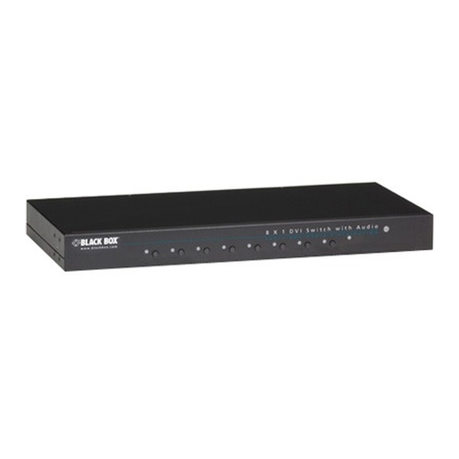
Figure 2-1 shows the front and back panels of the AVSW-DVI8X1. Table 2-1 describes its components.

Figure 2-1. 8X1 DVI and Audio switch front and back panels.
Table 2-1. 8X1 DVI and Audio switch components.
| Number in Fig. 2-1 | Component | Description |
| 1 | (8) Input LED indicators | On Yellow when port 1–8 is selected. Off when port 1–8 is not selected. |
| 2 | (1) Power LED indicator | On Green when power to the unit is on. Off when power to the unit is off. |
| 3 | (8) Push buttons | Press buttons 1–8 to select a port. |
| 4 | (1) Audio port (Output) | Connects to a speaker. |
| 5 | (8) Audio ports (Input) | Connect to audio sources 1–8. |
| 6 | (1) Video port (Output) | Connects to a display. |
| 7 | (8) Video ports (Input) | Connect to video sources 1–8. |
| 8 | EDID Copy button | Copy a monitor's EDID. |
| 9 | Serial port | Connects to a computer for serial control. |
| 10 | Power supply | Applies power to the unit. |
Installation
- Before installation, power off all devices that will be connected to this system.
- Make sure that all devices you will connect are properly grounded.
- Place cables away from fluorescent lights, air conditioners, and machines that are likely to generate electrical noise.
NOTE: If no screen displays, follow these steps:
- Make sure the device cables are correctly and firmly attached.
- Set your display device's input source as DVI.
- Check the PC BIOS configuration for the video output settings.
- Connect your computer to the display DIRECTLY to check if the video signal gets through.
Installation Steps
- Use a video cable (DVI) to connect the display to the video output port on the back of the switch. Plug a set of audio jacks from the speaker to the switch's speaker port.
- Use a video cable (DVI) to connect the source device to the video input port on the switch. Use an audio cable to connect the speaker port from the input side of the switch to the corresponding output port on the source device.
- Plug the power supply into the switch and power on the switch.
- Turn on the display (monitor, projector, or TV) and then power on the source device(s).
- If necessary, apply EDID Copy process to the unit.
NOTE: When each video source is powered on, make sure it has a display pointing to it for EDID communication. If a source does not have a display pointing to it, a video image might not display.
Operation
LED Indicator
The Power LED turns green when the video switch is powered on. When a video port is selected, its corresponding Port LED turns yellow.
Push Button
Press the corresponding button to select a port.
EDID Setting
In some cases, display problems may occur because of incorrect Extended Display Identification (EDID) communication between the display monitor and the unit. This function allows the system either to read the necessary EDID information from the unit, or to copy EDID from EDID-compliant displays.
Default Setting
To reset to the default EDID:
Step 1: Press and hold the "EDID Copy" button on the unit and release the button RIGHT AFTER the Power LED flashes red (6–7 seconds).
Step 2: The LED lights steady red and green indicating that the EDID default setting is completed.
Copy (New) Monitor EDID
When using a monitor (EDID-compliant) for display, the unit's EDID Copy function will enable EDID communication between the monitor and the unit for optimal video quality. Follow these steps:
Step 1: Power on the unit.
Step 2: Connect the EDID-compliant monitor to the switch and power on the monitor.
Step 3: Press the "EDID Copy" button for 3–5 seconds, and release the button RIGHT AFTER the Power LED flashes green.
Step 4: The Power LED flashes red and green alternately, then lights green indicating that the copy is successful.
NOTE: If the Power LED flashes red, the reason could be:
- The monitor is not connected.
- The monitor is not powered on.
- The EDID data of the monitor is not applicable
IR Remote Control
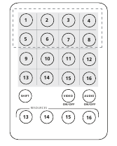
Figure 5-1. Remote control.
The remote control operates within a 1.5-ft. (5-m) range of the DVI switch. To select a source device with a remote control, press the number button (1–8) to directly switch to the corresponding port.
NOTES:
- Remove the battery protector on the remote control before operation.
- On the remote control, only buttons 1–8 are activated. The rest of the buttons are reserved for other models.
Serial Control
The DVI and audio switches' built in serial interface enables users to control the switch via a PC, serial controller devices, or home theater system. The controller's serial port should be configured as shown in Table 6-1.
Table 6-1. Serial parameters settings.
| Parameter | Setting |
| Baud Rate | 9600 |
| Data Bits | 8 |
| Parity | None |
| Stop Bits | 1 |
| Flow Control | None |
To select a source device via serial interface, select the number that corresponds to the port. For example, send "1" to switch to Port 1.
© Copyright 2013. Black Box Corporation. All rights reserved. Black Box® and the Double Diamond logo are registered trademarks of BB Technologies, Inc. Any third-party trademarks appearing in this manual are acknowledged to be the property of their respective owners.
724-746-5500
blackbox.com

Documents / Resources
References
Download manual
Here you can download full pdf version of manual, it may contain additional safety instructions, warranty information, FCC rules, etc.
Download Black Box AVSW-DVI8X1 - 8x1 DVI And Audio Switch Manual
Advertisement
Thank you! Your question has been received!


Need Assistance?
Do you have a question about the AVSW-DVI8X1 that isn't answered in the manual? Leave your question here.