Yamaha STAGEPAS 500 - Portable PA System Manual
- Service manual (72 pages) ,
- Owner's manual (4 pages) ,
- Owner's manual (2 pages)
Advertisement
Introduction
In order to get the most out of your new STAGEPAS 500 and its sophisticated functions, we suggest you read through this manual thoroughly. Also keep it in a safe place for future reference.
Features
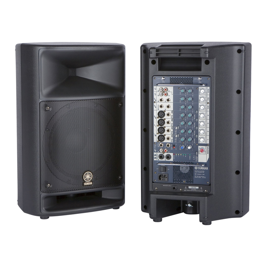
- Two-way, 10-inch (25 cm) speaker system
The built-in speakers deliver high-quality powerful sound from an exceptionally compact cabinet.
The scratch-resistant speakers are rugged enough for outdoor use. - Powered mixer
The powered mixer is a convenient, high-performance all-in-one unit that includes EQ and reverb. With four monaural inputs and three stereo inputs, the STAGEPAS 500 can be connected to a wide range of instruments and devices. - Convenient storage
The STAGEPAS 500 can be used in even the most cramped quarters, inside or outside, since the mixer is built into one of the speaker cabinets. The other speaker has a special compartment for storing speaker cables and microphones, letting you put all you need for your performance in one convenient place.
Package Contents
Two speakers (500S), mixer, panel, power cord, two speaker cables, Owner's Manual (this booklet)
NOTE: The mixer and the panel are installed in the speakers when the STAGEPAS 500 leaves the factory.
Before turning on the mixer
Remove the mixer
- Be sure that the mixer's power switch is turned off.
- Use a screwdriver or coin to turn each screw on the mixer from LOCK to OPEN until it clicks.

- Securely hold the mixer's handles to remove it from the speaker.


Use only the mixer's handles when removing the mixer from the speaker and when carrying the mixer separate from the speaker.
NOTE: The mixer can also be used when installed in the speaker.
When you install the mixer into the speaker, make sure to match the indentations on the speaker cabinet to the corresponding parts on the mixer, and then turn each screw from OPEN to LOCK until it clicks.
Turning the power on/off
- Be sure that the mixer's power switch is turned off.
- Connect the included power cord to the [AC IN] jack, and plug the power cord into a power outlet.

![]()
- To avoid any loud, unexpected noise from the speakers, first turn on the power to those connected devices that are closest to the sound source. Example: Sound source (CD player or instrument) → STAGEPAS 500 When turning off the power to the system, reverse the order described above.
- Before turning on the power, set the LEVEL controls and MASTER LEVEL control to their minimum setting (zero).
- Press the mixer's power switch to the ON position.
The POWER indicator lights.
To turn the power off, press the power switch to the OFF position.
The POWER indicator turns off.

Quick Guide
Getting sound out of the system
Using the included speakers, set up the system and try it out.
- Connect the included speakers and your instruments to the mixer.
Connect the included speakers (500S) to the SPEAKERS L/R jack. Connect the sources (guitar, other instruments) to the input jacks. For details, see "Connection Example."
![]()
Before connecting any devices, make sure to turn off the power for all devices (including microphones). Also, before turning the power on or off, set the volume levels on all devices to minimum.
NOTE: For best results when connecting an electric guitar or bass guitar to the mixer, use a direct box, preamp (guitar amp), or amp simulator. - Set the mixer's LEVEL controls and MASTER LEVEL control to the minimum (zero).

- Depending on the device used, set the MIC/LINE switch to MIC (
![]() ) or LINE (
) or LINE (![]() ) as appropriate.
) as appropriate.
For low-level signals (such as that of microphones), set the switch to the MIC (![]() ) position.
) position.
For high-level signals (such as keyboard instruments and audio equipment), set the switch to the LINE (![]() ) position.
) position.
![]()
NOTE: When using a condenser microphone, set the PHANTOM switch to ON. - Turning the power on
First, turn on the power to any connected devices, then turn the STAGEPAS 500 power on.
If you've connected powered speakers to the mixer, turn on the power of the mixer first, then the powered speakers.
![]()
![]()
To avoid any loud, unexpected noise from the speakers, first turn on the power to those connected devices that are closest to the sound source.
Example: Sound source (CD player or instrument) → STAGEPAS 500 → (Power amplifier) When turning off the power to the system, reverse the order described above. - Set the MASTER LEVEL control to the optimum position (indicated by the arrow).

- While playing your instrument or singing into the microphone, adjust the LEVEL control of the corresponding channel.
Adjust the LEVEL Control of the corresponding channel so that the "0" LED lights up momentarily.

- Use the MASTER LEVEL control to adjust the overall volume.
![]()
If the LIMITER indicator flashes continuously, the internal power amplifier section is being excessively overloaded and may malfunction.


Applying reverb or echo to the sound
Reverb recreates the warm ambience of an actual performance space, such as a concert hall or a night club.
- For each channel you want to apply reverb, set the corresponding REVERB switch to ON (
![]() ).
).

- Use the REVERB control to adjust the overall reverb.


Connection Example
The STAGEPAS 500 can be used in a wide variety of sound reinforcement applications, from a full-band performance onstage to solo street performance—providing a powerful, high-performance system in an exceptionally compact and portable package. Connect a guitar or a microphone to the monaural input jacks (channels 1 to 4) and connect a keyboard to the stereo input jacks (channels 5/6 to 9/10).
If you have a powered speaker, you can connect it to the MONITOR OUT jack for monitoring your vocals. For optimum results in band performance applications and to create a more powerful sound for music, make sure to set the SPEECH/MUSIC switch to MUSIC.
NOTE: For best results when connecting an electric guitar or bass guitar to the mixer, use a direct box, preamp (guitar amp), or amp simulator.

Block Diagram

Controls and Functions

- AC IN jack
Connect the included power cord here.
![]()
Be sure to use the included power cord. Use of other cords may result in malfunction, heat generation, or fire. - POWER switch
For turning the power to the mixer on and off. - SPEAKERS L/R jacks (for included speakers (500S) only)
These output the mixed signal channels from 1 to 9/10, and the level is adjusted with the MASTER LEVEL control. Connect only the included speakers (500S). - REC OUT L/R jacks
These output the mixed signal channels from 1 to 9/10, and the level is unaffected by the MASTER LEVEL control. You can use these jacks, for example, to connect to an external recorder. - MONITOR OUT L (MONO) /R jacks
These output the mixed signal channels from 1 to 9/10, and the level is adjusted with the MONITOR OUT control. These jacks are convenient for connecting an external powered speaker for monitoring purposes. - Channel input jacks (CH 1 to 4)
For connecting a guitar, microphone, keyboard or other instrument/device. Set the MIC/LINE switch to MIC or LINE for channels 1 to 4, depending on the level of the input signal. XLR-type connectors are wired as follows (IEC60268 standard): pin 1: ground, pin 2: hot (+), and pin 3: cold (-).
NOTE: On any given channel, you may use either XLR or phone jack, but not both. Please connect to only one of these jacks on each channel. - Stereo channel input jacks (CH 5/6, 7/8, 9/10)
Input the left and right channels of a stereo signal into the respective odd and even channels of the mixer. These inputs are intended mainly for use with instruments and equipment having stereo outputs, such as a synthesizer or CD player.
NOTE: The channel 7/8 input provides two sets of jacks—both phone jacks and RCA-pin jacks. Either one of these jacks may be used, but not both at the same time. Please connect to only one of these jacks on each channel. - MIC/LINE switch
Set this switch to MIC or LINE for channels 1 to 4, depending on the level of the input signal. For low-level signals (such as that of microphones), set the switch to the MIC (![]() ) position. For high-level signals (such as keyboard instruments and audio equipment), set the switch to the LINE (
) position. For high-level signals (such as keyboard instruments and audio equipment), set the switch to the LINE (![]() ) position.
) position.
![]()
To avoid damage to speakers, be sure to turn off amplifiers (or powered speakers) before setting this switch to MIC or LINE. We also recommend that you turn the MASTER LEVEL control to the minimum setting before operating the switch, to avoid excessively loud noises that could cause hearing loss or device damage. - PHANTOM switch
If you set the switch on, the mixer supplies phantom power on to the XLR mic input jacks on the channels 1 to 4.
![]()
- Be sure to leave this switch OFF if the device or instrument that you are using does not require phantom power.
- When using phantom power, do not connect any devices other than condenser microphones to the XLR input jacks. Other devices may be damaged if connected to phantom power. This precaution does not apply to balanced dynamic microphones, however, as these will not be affected by phantom power.
- To avoid damage to speakers, be sure to turn off amplifiers (or powered speakers) before turning this switch on or off. We also recommend that you turn the MASTER LEVEL control to the minimum setting before operating the switch, to avoid excessively loud noises that could cause hearing loss or device damage.
- LIMIT/COMP switch
Set this switch to COMP (![]() ) to apply compression, or set it to LIMIT (
) to apply compression, or set it to LIMIT (![]() ) to apply limiting. By compressing excessive peaks of input signals and bringing up the level of overly soft parts, compression raises the overall volume without introducing distortion. Compression can be used to make a mix sound louder and have more punch. The Limiter is used to suppress excessive input signals and bring them down to an adequate level. The switch lights up in yellow when it is set to COMP (
) to apply limiting. By compressing excessive peaks of input signals and bringing up the level of overly soft parts, compression raises the overall volume without introducing distortion. Compression can be used to make a mix sound louder and have more punch. The Limiter is used to suppress excessive input signals and bring them down to an adequate level. The switch lights up in yellow when it is set to COMP (![]() ).
). - Equalizer
HIGH: Determines the level of the high frequency band for each channel. Rotating the knob clockwise boosts the high frequencies and produces a clearer, crisper sound. If you start getting feedback (a high-pitched squealing sound) or you want to make the sound softer and less harsh, turn the knob counterclockwise slightly.
LOW: Determines the level of the low frequency band for each channel. Rotating the knob clockwise boosts the low frequencies and produces a deeper, warmer sound. If you start getting feedback or you want to make the sound less boomy, turn the knob counterclockwise slightly. - REVERB switch
Set this switch to ON to recreate the rich ambience of various performance environments, such as a concert hall or a night club. The switch lights up in green when REVERB is ON (![]() ).
). - REVERB control
Determines the overall level of the reverb or echo that is applied to the output signal. For best results, this level should not be set very high, to avoid possible feedback and to prevent the sound from becoming "muddy" with too much reverb. - LEVEL control
Use these controls to adjust the volume balance among the various channels.
![]()
To reduce noise, set any LEVEL controls on unused channels to the minimum. - MASTER LEVEL Control
Determines the volume of the signal output from the SPEAKERS L/R jacks. This allows you to adjust the overall volume without changing the relative volume balance among the various channels (made with the LEVEL controls) or the tone settings (made with the Equalizer). - SPEECH/MUSIC switch
Set this switch to SPEECH (![]() ) to optimize the mixer settings and sound quality for speech purposes and announcements. Set this to MUSIC (
) to optimize the mixer settings and sound quality for speech purposes and announcements. Set this to MUSIC (![]() ) to optimize the mixer for musical performance. The switch lights up in yellow when it is set to MUSIC (
) to optimize the mixer for musical performance. The switch lights up in yellow when it is set to MUSIC (![]() ).
). - MONITOR OUT Control
Determines the signal level output from the MONITOR OUT jacks.
NOTE: The MASTER LEVEL Control does not affect the signal via the MONITOR OUT Control.
Troubleshooting
Power does not turn on
- Is the included power cord correctly connected to a power outlet?
Power shuts down suddenly
- Is the vent on the top panel of the mixer blocked? Since inadequate ventilation can result in overheating the mixer, the power may be turned off automatically and the mixer may reset itself.
- Is the LIMITER flashes continuously? If the internal power amplifier section is excessively overloaded, the power may be turned off automatically and the mixer may reset itself.
No sound is heard
- Are external instruments (including a microphone) or speakers correctly connected to the mixer?
- Are the LEVEL controls of all relevant channels and/or the MASTER LEVEL control set to appropriate levels?
- Are the SPEAKERS L/R jacks connected to the included speakers (500S)?
- Are the included speaker cables used?
If the connector of a speaker cable other than the included speaker cable touches any metal parts such as the mixer's handle, no sound may result because of a short circuit.
Use only the speaker cables included with the device. - Is the POWER indicator flashing? There may be a short in the speaker cable or the connection may be faulty. Check that the speaker cable is correctly connected to the mixer and reapply the power.
- If sound is not still output, contact your Yamaha dealer.
Sound is distorted or noise is produced
- Are the LEVEL controls of all relevant channels and/or the MASTER LEVEL control set to appropriate levels?
- Are the MIC/LINE switches of each channels set appropriately?
- Are both XLR type and phone type jacks on channels 1–4 being used (connected) at the same time?
Please connect to only one of these jacks on each channel. - Is the input signal from the connected device set to an appropriate level?
- Use channels 1 or 2, and set the LIMIT/COMP switches to COMP (
![]() ). Compression may be effective in preventing distortion.
). Compression may be effective in preventing distortion.
Sound is not loud enough
- Are the LEVEL controls of all relevant channels and/or the MASTER LEVEL control set to appropriate levels?
- Are the MIC/LINE switches of each channels set appropriately?
- Are both XLR type and phone type jacks on channels 1–4 being used (connected) at the same time?
Please connect to only one of these jacks on each channel. - Is the input signal from the connected device set to an appropriate level?
- Is the PHANTOM switch set to ON when using a condenser microphone?
Reverb is not applied to the sound
- Are the REVERB switches of each channels set to ON (
![]() )?
)? - Is the REVERB control set to an appropriate level?
Changing the sound quality
- Are the Equalizer controls (HIGH/LOW) set to appropriate levels?
- If you want to get a more powerful sound from the speakers, set the SPEECH/MUSIC switch to MUSIC (
![]() ).
). - If you want to get a clearer sound for announcements, set the SPEECH/MUSIC switch to SPEECH (
![]() ).
).
Using a single speaker
- You can use a single speaker. If you use a single speaker, the mixer outputs just one channel of the stereo signal, left or right.
Outputting the signal for monitoring
- Connect a powered speaker to the MONITOR OUT jack. The MONITOR OUT jack outputs the signal prior to routing through the MASTER LEVEL control. Adjust the level of output signal from the MONITOR OUT jack with the MONITOR OUT control. The MONITOR OUT control does not affect the MASTER LEVEL control. If only the L (left) MONITOR OUT jack is used, the mixer mixes the left and right signals and sends them to the jack.
Convenient built-in storage compartment

The STAGEPAS 500 features a convenient storage compartment in the speaker box for packing the included power cable, speaker cable, Owner's Manual (this booklet), and an optional microphone and the cable, as shown above. Remove the rear panel of the speaker and put in the things you need. Carry the STAGEPAS 500 with you, and you've got all you need to set up and perform—anywhere, anytime.


TO REDUCE THE RISK OF ELECTRIC SHOCK, DO NOT REMOVE COVER (OR BACK). NO USER-SERVICEABLE PARTS INSIDE. REFER SERVICING TO QUALIFIED SERVICE PERSONNEL.
The above warning is located on the bottom of the mixer and the rear of the speakers.
Explanation of Graphical Symbols
 The lightning flash with arrowhead symbol within an equilateral triangle is intended to alert the user to the presence of uninsulated "dangerous voltage" within the product's enclosure that may be of sufficient magnitude to constitute a risk of electric shock to persons.
 The above warning is located on the bottom The exclamation point within an equilateral triangle is intended to alert the user to the presence of important of the mixer and the rear of the speakers. operating and maintenance (servicing) instructions in the literature accompanying the product.
IMPORTANT SAFETY INSTRUCTIONS
- Read these instructions.
- Keep these instructions.
- Heed all warnings.
- Follow all instructions.
- Do not use this apparatus near water.
- Clean only with dry cloth.
- Do not block any ventilation openings. Install in accordance with the manufacturer's instructions.
- Do not install near any heat sources such as radiators, heat registers, stoves, or other apparatus (including amplifiers) that produce heat.
- Do not defeat the safety purpose of the polarized or grounding-type plug. A polarized plug has two blades with one wider than the other. A grounding type plug has two blades and a third grounding prong. The wide blade or the third prong are provided for your safety. If the provided plug does not fit into your outlet, consult an electrician for replacement of the obsolete outlet.
- Protect the power cord from being walked on or pinched particularly at plugs, convenience receptacles, and the point where they exit from the apparatus.
- Only use attachments/accessories specified by the manufacturer.
- Use only with the cart, stand, tripod, bracket, or table specified by the manufacturer, or sold with the apparatus. When a cart is used, use caution when moving the cart/apparatus combination to avoid injury from tip-over.
![]()
- Unplug this apparatus during lightning storms or when unused for long periods of time.
- Refer all servicing to qualified service personnel. Servicing is required when the apparatus has been damaged in any way, such as power-supply cord or plug is damaged, liquid has been spilled or objects have fallen into the apparatus, the apparatus has been exposed to rain or moisture, does not operate normally, or has been dropped.


TO REDUCE THE RISK OF FIRE OR ELECTRIC SHOCK, DO NOT EXPOSE THIS APPARATUS TO RAIN OR MOISTURE.
PRECAUTIONS
PLEASE READ CAREFULLY BEFORE PROCEEDING
* Please keep this manual in a safe place for future reference.

Always follow the basic precautions listed below to avoid the possibility of serious injury or even death from electrical shock, short-circuiting, damages, fire or other hazards. These precautions include, but are not limited to, the following:
Power supply/Power cord
- Only use the voltage specified as correct for the device. The required voltage is printed on the name plate of the device.
- Use only the included power cord.
- Do not place the power cord near heat sources such as heaters or radiators, and do not excessively bend or otherwise damage the cord, place heavy objects on it, or place it in a position where anyone could walk on, trip over, or roll anything over it.
- Be sure to connect to an appropriate outlet with a protective grounding connection. Improper grounding can result in electrical shock.
Do not open
- Do not open the device or attempt to disassemble the internal parts or modify them in any way. The device contains no user-serviceable parts. If it should appear to be malfunctioning, discontinue use immediately and have it inspected by qualified Yamaha service personnel.
Water warning
- Do not expose the device to rain, use it near water or in damp or wet conditions, or place containers on it containing liquids which might spill into any openings.
- Never insert or remove an electric plug with wet hands.
If you notice any abnormality
- If the power cord or plug becomes frayed or damaged, or if there is a sudden loss of sound during use of the device, or if any unusual smells or smoke should appear to be caused by it, immediately turn off the power switch, disconnect the electric plug from the outlet, and have the device inspected by qualified Yamaha service personnel.
- If this device should be dropped or damaged, immediately turn off the power switch, disconnect the electric plug from the outlet, and have the device inspected by qualified Yamaha service personnel.
Always follow the basic precautions listed below to avoid the possibility of physical injury to you or others, or damage to the device or other property. These precautions include, but are not limited to, the following:
Power supply/Power cord
- Remove the electric plug from the outlet when the device is not to be used for extended periods of time, or during electrical storms.
- When removing the electric plug from the device or an outlet, always hold the plug itself and not the cord. Pulling by the cord can damage it.
Location
- When transporting or moving the device, always use two or more people. Attempting to lift the device by yourself may damage your back, result in other injury, or cause damage to the device itself.
- Before moving the device, remove all connected cables.
- When setting up the device, make sure that the AC outlet you are using is easily accessible. If some trouble or malfunction occurs, immediately turn off the power switch and disconnect the plug from the outlet.
- Do not use the device in a confined, poorly-ventilated location. Make sure that there is adequate space between the mixer and surrounding walls or other devices: at least 30 cm at the sides, 30 cm behind and 30 cm above. If the mixer is to be used installed into the speaker cabinet, make sure to allow adequate space between the speaker and the surrounding walls or other devices: at least 30 cm at the sides, 30 cm behind and 30 cm above. Inadequate ventilation can result in overheating, possibly causing damage to the device(s), or even fire.
- Do not use the speaker's handles for suspended installation. Doing so can result in damage or injury.
- Avoid setting all equalizer controls and faders to their maximum. Depending on the condition of the connected devices, doing so may cause feedback and may damage the speakers.
- Do not expose the device to excessive dust or vibrations, or extreme cold or heat (such as in direct sunlight, near a heater, or in a car during the day) to prevent the possibility of panel disfiguration or damage to the internal components.
- Do not place the device in an unstable position where it might accidentally fall over.
- Do not block the vents. This mixer has ventilation holes at the top to prevent the internal temperature from becoming too high. In particular, do not place the device on its side or upside down. Inadequate ventilation can result in overheating, possibly causing damage to the device(s), or even fire.
- Do not use the device in the vicinity of a TV, radio, stereo equipment, mobile phone, or other electric devices. Doing so may result in noise, both in the device itself and in the TV or radio next to it.
Connections
- Before connecting the device to other devices, turn off the power for all devices. Before turning the power on or off for all devices, set all volume levels to minimum.
- For the SPEAKERS jacks, Use only the included speakers (500S) and speaker cables. Use of other types of speakers and cables may result in damage to the device(s), or even fire.
Handling caution
- When turning on the AC power in your audio system, always turn on the device LAST, to avoid speaker damage. When turning the power off, the device should be turned off FIRST for the same reason.
- Do not insert your fingers or hands in any gaps or openings on the device (vents,, ports, etc.).
- Avoid inserting or dropping foreign objects (paper, plastic, metal, etc.) into any gaps or openings on the device (vents, ports, etc.) If this happens, turn off the power immediately and unplug the power cord from the AC outlet. Then have the device inspected by qualified Yamaha service personnel.
- Do not use the device for a long period of time at a high or uncomfortable volume level, since this can cause permanent hearing loss. If you experience any hearing loss or ringing in the ears, consult a physician.
- Do not operate the device if the sound is distorting. Prolonged use in this condition could cause overheating and result in fire.
- Do not rest your weight on the device or place heavy objects on it, and avoid use excessive force on the buttons, switches or connectors.
Protective Circuit (poly switch)
All full-range loudspeakers are fitted with a self-resetting poly switch that protects the high-frequency driver from damage caused by excessive power. If a loudspeaker cabinet loses high-frequency output, immediately remove power from the unit and wait for two to three minutes. This should be long enough to allow the poly switch to reset. Reapply power and check the performance of the high frequency driver before continuing, with the power reduced to a level that does not cause the poly switch to interrupt the signal.
Interference From Cell Phones
Using a cell phone near the speaker system can induce noise. If this occurs, move the cell phone further away from the speaker system. Air blowing out of the bass reflex ports is normal, and often occurs when the speaker is handling program material with heavy bass content.
Yamaha cannot be held responsible for damage caused by improper use or modifications to the device.
Always turn the power off when the device is not in use. The performance of components with moving contacts, such as switches, volume controls, and connectors, deteriorates over time. Consult qualified Yamaha service personnel about replacing defective components.

Please record the serial number of this unit in the space below.
Model: Serial No.:
The serial number is located on the bottom or rear of the unit. Retain this Owner's Manual in a safe place for future reference.
Dimensions

Specifications
- General Specifications
Maximum Output Power
250 W + 250 W (±10%)/4 Ω @ 10% THD at 1 kHz (SPEAKERS L/R)
![]() 200 W + 200 W/4 Ω @ 1% THD at 1 kHz (SPEAKERS L/R)
200 W + 200 W/4 Ω @ 1% THD at 1 kHz (SPEAKERS L/R)
Maximum Output Level
116 dB (1 m)
Frequency Response (Nomimal output level @ 1 kHz)
-3 dB, 0 dB, +1 dB @ 20 Hz-20 kHz (MUSIC/SPEECH=MUSIC) (MONITOR OUT)
-3 dB, 0 dB, +1 dB @ 80 Hz-20 kHz (MUSIC/SPEECH = SPEECH) (REC OUT)
-3dB, 0dB, +1 dB @ 20 Hz-20 kHz, 1 W Output (MUSIC/SPEECH=MUSIC, without Speaker EQ) (SPEAKERS L/R)
Total Harmonic Distortion
![]() 0.5% @ 20 Hz, 1 kHz, 20 kHz +14 dBu GAIN= nominal (MONITOR OUT, REC OUT)
0.5% @ 20 Hz, 1 kHz, 20 kHz +14 dBu GAIN= nominal (MONITOR OUT, REC OUT)
Hum & Noise (Equivalent Input Noise, Rs = 150Ω, MIC/LINE = MIC)
![]() -106 dBu (CH1/2)
-106 dBu (CH1/2)
![]() -112 dBu (CH3/4)
-112 dBu (CH3/4)
![]() -65 dBu Residual output noise (SPEAKERS L/R)
-65 dBu Residual output noise (SPEAKERS L/R)
Crosstalk (1 kHz)
![]() -70 dB between input channels
-70 dB between input channels
Phantom Voltage
+15 V (CH1-4)
LIMIT/COMP switch
ON = Comp, OFF = Limit (CH1/2)
Power Consumption
65 W
Weight
24 kg (Speaker x 2 + Powered Mixer)
Stereo Input Channel Equalization
±15 dB
HIGH 10 kHz shelving
LOW 100 Hz shelving - Speakers (500S)
Enclosure
2 way bass-reflex type, Polypropylene, Black
Crossover Frequency
4.0 kHz (LF: 12 dB/oct, HF: 12 dB/oct)
Frequency Range
55 Hz-20 kHz (-10 dB)
Speaker Unit
LF: 10" (25 cm) Cone
HF: 1" (2.54cm) Compression Driver


Documents / ResourcesDownload manual
Here you can download full pdf version of manual, it may contain additional safety instructions, warranty information, FCC rules, etc.
Advertisement
Thank you! Your question has been received!


Need Assistance?
Do you have a question about the STAGEPAS 500 that isn't answered in the manual? Leave your question here.