
Related Manuals for LG HT905TAW


Summary of Contents for LG HT905TAW
- Page 1 Internal Use Only Website http://biz.lgservice.com DVD RECEIVER SYSTEM SERVICE MANUAL MODEL: HT905TAW (HT905TAW, SH95TA-F/ S/ C/ W, W95) P/NO : AFN73671966 MARCH, 2010...
-
Page 2: Table Of Contents
[CONTENTS] SECTION 1. GENERAL • SERVICING PRECAUTIONS ..........1-2 •... -
Page 3: Section 1. General
SECTION 1. GENERAL SERVICING PRECAUTIONS NOTES REGARDING HANDLING OF THE PICK-UP 1. Notes for transport and storage 1) The pick-up should always be left in its conductive bag until immediately prior to use. 2) The pick-up should never be subjected to external pressure or impact. Storage in conductive bag Drop impact 2. - Page 4 NOTES REGARDING COMPACT DISC PLAYER REPAIRS 1. Preparations 1) Compact disc players incorporate a great many ICs as well as the pick-up (laser diode). These components are sensitive to, and easily affected by, static electricity. If such static electricity is high voltage, components can be damaged, and for that reason components should be handled with care.
-
Page 5: Esd Precautions
ESD PRECAUTIONS Electrostatically Sensitive Devices (ESD) Some semiconductor (solid state) devices can be damaged easily by static electricity. Such components commonly are called Electrostatically Sensitive Devices (ESD). Examples of typical ESD devices are integrated circuits and some field-effect transistors and semiconductor chip components. The following techniques should be used to help reduce the incidence of component damage caused by static electricity. -
Page 6: Service Information For Eeprom
SERVICE INFORMATION FOR EEPROM POWER ON DETECT NEW EEPROM DVD LOGO Status (NO Disk status) (OPTION EDIT SCREEN) NAME Remote control OPT 1 Pause key→1→4→7→2 in order. OPT 2 OPT 3 OPT 4 OPT 5 OPT 6 Press number 0~9, Press character OPT 7 A~F (1~6 for a while) OPT 8... -
Page 7: How To Update Audio Micom & Dvd Programs
HOW TO UPDATE AUDIO MICOM & DVD PROGRAMS 1. How to update AUDIO MICOM program. [Update using CD] 1. Change the filename to download as “HT905_(Version).HEX”. Only upper cases are permitted. ex) HT905 : “HT905_0709081.HEX” 2. Copy the file to the root folder of a CD and burn it. 3. -
Page 8: Specifications
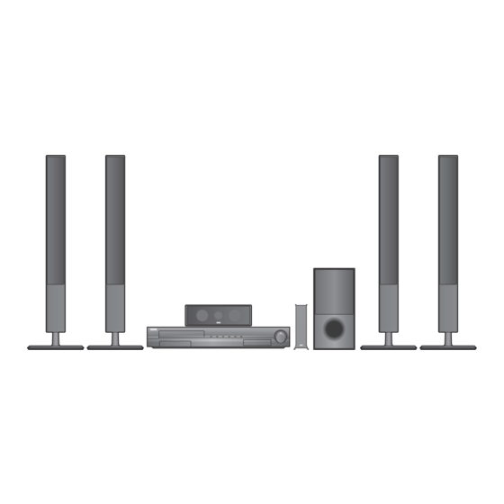
SPECIFICATIONS GENERAL Power requirements Refer to main label. Power consumption Refer to main label. Dimensions (W x H x D) 430 x 62.5 x 281 mm without foot Net Weight (Approx.) 4.0 kg Operating temperature 41 °F to 95 °F (5 °C to 35 °C) Operating humidity 5 % to 90 % Bus Power supply (USB) - Page 9 SPEAKERS Front speaker Type 2 Way 3 speaker Impedance Rated 4 Ω Input Power 180 W Max. Input power 360 W Net Dimensions (W x H x D) 270 x 1050 x 225 mm Net Weight 3.1 kg Rear speaker Type 2 Way 2 speaker Impedance Rated...
-
Page 10: Section 2. Electrical Part
SECTION 2. ELECTRICAL PART TROUBLESHOOTING GUIDE 1. SMPS BOARD No power Check the AC Connect the open line line pattern Check fuse F901 Replace F901 Low impedance: Check BD901 “+” to “-” pin impedance Replace IC901, BD901 Check C976 Check a 3.7 V lines short voltage (3.9 V) Replace PC972, IC902's components Check C963... - Page 11 No sound Check IC961 Check no power list, AC input voltage Vcc voltage (34 V ~ 43 V) Check C955 Check AMP module short voltage (25 V or 36 V) Replace PC951, IC901 Replace IC961, IC901 or SMPS board...
- Page 12 2. POWER KEY BOARD POWER cord insert Stand by LED (LD305) CN331, PN301 cable Connect 3p Harness cable turn on? connection ok? (PN301) CN331 pin2 power ok? Check MAIN and SMPS board Replace LED(LD305) When you press Check FRONT board power key, “WELCOME”...
- Page 13 3-1. FRONT BOARD (HB905 / HT905) Power on “WELCOME CN307 cable PLEASE WAIT” Display Connect 26p FFC cable connection ok? on VFD ok? CN306 pin4, 5, 6 Check SMPS board power ok? CN307 pin14, 15, 16 Check MAIN board data signal ok? IC301 Replace IC301 check ok?
- Page 14 3-2. FRONT BOARD (HB965 / HT965) Power on “WELCOME CN307 cable PLEASE WAIT” Display Connect 26p FFC cable connection ok? on VFD ok? CN306 pin4, 5, 6 Check SMPS board power ok? CN307 pin14, 15, 16 Check MAIN board data signal ok? IC301 Replace IC301 check ok?
- Page 15 4. NO AUDIO CHECK CD/DVD Disc AUX function or USB play IC200 pin7, 8 IC201 pin6, 8, 10, 25 Check IC500 Check JK202 audio L/R ok? I2S input signal ok? IC500 pin156, 157, 161, 162 Check IC500 I2S output signal PORTABLE function OPTICAL function IC200 pin21, 22...
- Page 16 IPOD function TUNER Function Check Tuner (TU100) IPOD B/D IC200 audio L/R ok? and Antenna connec- Check IPOD JK3P1 pin27, 28 tion audio L/R ok? connection or JK3P1 IC200 pin42, 43, 44 I2S Check IC500 and X500 clock ok? FRONT B/D Check 14p FFC cable CN307 pin10, 11 and connection...
- Page 17 5. NO VIDEO CHECK COMPONENT video out IC206 pin2, 3, 4 Check IC500 video signal ok? IC206 pin11, 12, 13 Check IC206 video signal ok? Check JK202 CVBS video out IC205 pin3 Check IC500 video signal ok? IC205 pin4 IC205 pin1 Check Micom (IC101) video signal ok? LOW signal?
- Page 18 CVBS video out (IPOD video) IPOD B/D Check iPod connection or JK3P1 pin23 video JK3P1 signal OK? Check 14p FFC cable and FRONT B/D CN307 pin8 ok? connection Check 26p FFC cable and con- MAIN B/D IC208 pin4 ok? nection IC205 pin1 Check IC208 video signal ok?
- Page 19 6. HDMI NO AUDIO/VIDEO CHECK (with HDMI IN) HDMI IN function Check CN803 and HDMI cable CN803 pin1, 3, 4, 6, 7, 9, 10, 12 connection TMDS data signal ok? CN803 Resolder CN803 soldering OK? IC803 video Check IC803 input signal (pin1~36) CN801 or CN802 Check IC803 and X801 pin1, 3, 4, 6, 7, 9, 10, 12 TMDS...
- Page 20 HDMI OUT function CN803 Check CN803 and HDMI cable pin1, 3, 4, 6, 7, 9, 10, 12 TMDS data connection signal ok? CN803 soldering ok? Resolder CN803 IC803 video input signal (pin1~36) Check IC803 IC500 TMDS data (R843 ~ R850) Check IC803 and X801 signal ok? Check IC500...
- Page 21 7. HDMI NO AUDIO/VIDEO CHECK (without HDMI IN) HDMI OUT function CN803 Check CN803 and HDMI cable pin1, 3, 4, 6, 7, 9, 10, 12 TMDS data connection signal ok? CN803 soldering ok? Resolder CN803 IC803 video input signal (pin1~36) Check IC803 IC500 TMDS data (R843 ~ R850) Check IC803 and X801...
- Page 22 8. System operation flow POWER ON. 1. Initializes SERVO, DSP & RISC registers. 2. Write RISC code to SDRAM. 3. Reset RISC. Show LOGO. Tray closed? Tray close to closed position. SLED at inner side? SLED moves to inner position. 1.
- Page 23 9. Test & debug flow TEST. Check the AC voltage Power PCBA (110 V Check the POWER PART. or 220 V). Switch on the Power PCBA. Are the Check the POWER PART. DC Voltage outputs OK? (from the SMPS). Are 3.7 V, 5.6 V and 12 V DC outputs normal on main Check the regulators or diode.
- Page 24 Power On. Check connection lines Flash between FLASH & MT1389FE/ Memory operates Show LOGO? GH and the FLASH access time properly? whether is suitable or not. Check connection lines SDRAM between SDRAM(IC503) works properly? & MT1389FE/GH and the SDRAM is damaged. MT1389FE/GH Check the related circuit of VIDEO outputs...
- Page 25 Does Motor the SLED move to inner Check the connection line of Driver M_STBY side when it is at outer M_STBY. pin is high? position? Motor Check the related circuit of Driver SLD SLD. pin is High? SLED+ and Check the amp circuit on SLED- output motor driver.
- Page 26 Check the laser power circuit Laser DVDLD or on MT1389FE/GH and turns on when CDLD output connecting to power reading disc? property? transistor.(Q400, Q401) Collector Check the related circuit on voltage of power transistor laser power transistor. is OK?(Q400, Q401) Check cable connection between transistor output and pick-up head.
- Page 27 Proper Check connections between signals on A, B, C, Focus on ok? MT1389FE/GH and pick-up head. D of MT1389FE/GH. Proper Check the related circuit on CD_DVDCT signal on MT1389FE/GH CD_DVDCT. MT1389FE/GH. Check CD_DVDCT connection between S3053 and MT1389FE/GH. Proper Check the related circuit on CD_DVDCT signal on Track On OK? MT1389FE/GH.
- Page 28 Check connection between Normal Audio IC201(Audio DSP) IC500 BCK, LRCK, ADATA0, output when disc received correct data ADATA1, ADATA2(Pins157, playback? stream? 158, 160, 161, 162). Normal Check the related circuit of Audio DSP IC out?(IC201). Check AMP board and 22P FFC cable.
-
Page 29: Details And Waveforms On System Test And Debugging
DETAILS AND WAVEFORMS ON SYSTEM TEST AND DEBUGGING 1. SYSTEM 27 MHz CLOCK,RESET,FLASH R/W SIGNAL 1) MT1389FE/GH main clock is at 27 MHz(X500) FIG 1-1 2) MT1389FE/GH reset is high active. Power Cord in P_CTL DVD_RST RESET_IN IC101 FIG 1-2 IC101 2-20... - Page 30 3) Flash R/W enable signal during download(Downloading) SF_DI SF_DO FIG 1-3 2. SDRAM CLOCK 1) MT1389FE/GH main clock is at 27 MHz(X500) DCLK = 93 MHz, Vp-p = 2.2, Vmax = 2.7 V SDCLK FIG 2-1 2-21...
- Page 31 3. VIDEO PART-1 (100% FULL COLOR-BAR) CVBS_I 2-22...
- Page 32 4. VIDEO PART-2 (100% FULL COLOR-BAR) CVBS COMP_Y COMP_Pb COMP_Pr 2-23...
- Page 33 5. HDMI PART HDMI_SDA HDMI_SCL HDMI_CLK HDMI_DATA 2-24...
- Page 34 6. SERVO OPEN/CLOSE SIGNAL 1) Tray open/close waveform 2) Tray close waveform OPENSW OPENSW CLOSESW CLOSESW OPEN OPEN CLOSE CLOSE FIG 3-1 FIG 3-2 3) Tray open waveform OPENSW CLOSESW OPEN CLOSE FIG 3-3 2-25...
- Page 35 4) SLED CONTROL RELATED SIGNAL (NO DISC CONDITION) M-STBY FIG 4-1 2-26...
- Page 36 5) LENS CONTROL RELATED SIGNAL(NO DISC CONDITION) FIG 5-1 6) LASER POWER CONTROL RELATED SIGNAL(NO DISC CONDITION) IC500 MDI1 DVDLD CDLD FIG 6-1 2-27...
- Page 37 7) DISC TYPE JUDGEMENT WAVEFORMS PU_DET IC400 FIG 7-1 (DVD) 35 : This signal can see using special debug program IC500 PU_DET FIG 7-2 (DVD) 2-28...
- Page 38 PU_DET IC400 FIG 7-3 (CD) 38 : This signal can see using special debug program IC500 PU_DET FIG 7-4 (CD) 2-29...
- Page 39 8) FOCUS ON WAVEFORMS 25 : This signal can see using special debug program IC500 PU_DET FIG 8-1 (DVD) PU_DET FIG 8-2 (CD) IC400 2-30...
- Page 40 9) SPINDLE CONTROL WAVEFORMS (NO DISC CONDITION) SPIND IC400 FIG 9-1 2-31...
- Page 41 10) TRACKING CONTROL RELATED SIGNAL(System checking) 47 : This signal can see using special debug program IC500 PU_DET PU_DET FIG 10-1(DVD) PU_DET PU_DET IC400 FIG 10-2(CD) IC400 2-32...
-
Page 42: Wiring Diagram
WIRING DIAGRAM HDMI HDMI HDMI HDMI HDMI HDMI SPK JACK SPK JACK TUNER TUNER Wireless Wireless (OPTION) (OPTION) CN701 CN701 CN2W1 CN2W1 12P FFC 12P FFC CN105 CN105 CN601 CN601 MAIN MAIN CN400 CN401 CN401 CN400 23P FFC 9P FFC 9P FFC 23P FFC CN103... -
Page 43: Block Diagrams
BLOCK DIAGRAMS 1. MAIN BLOCK DIAGRAM 3.3 V/5 V 24.576 MHZ 3.3 V_M 2ch ADC MICOM +12 V 1.8 V MICOM (CS5346) NJM2794 SANYO 100P SANYO 100P Audio DSP I-POD DC-DC DC-DC 3.3 V 3.3 V_M MP8706 MP8706 CS48560 Flash 9.8304MHZ PORTABLE PORTABLE... - Page 44 2. FRONT/POWER/AMP BLOCK DIAGRAM SMPS Main PCB +3.7 VA, +12 V, +5.6 V Amp PCB +32 V/39 V, +12 V, -12 V, +5.6 V FRONT(VFD) Front PCB +FL, -FL, VKK, +5.6 V PT6315 PT6315 32 V/39 V/12 V FL/FR(2ch) 3.3 V + 12V TAS5613 MC4580...
-
Page 45: Circuit Diagrams
CIRCUIT DIAGRAMS IMPORTANT SAFETY NOTICE CIRCUIT. SPECIAL COMPONENTS ARE SHADED ON NOTE : THE SCHEMATIC FOR EASY IDENTIFICATION. 1. Shaded( ) parts are critical for safety. Replace only WHEN SERVICING THIS CHASSIS, UNDER NO THIS CIRCUIT DIAGRAM MAY OCCASIONALLY with specified part number. 1. - Page 46 2. MPEG CIRCUIT DIAGRAM MPEG EBY60684401(#1) Rev 9.6 WAVEFORM 2010.03.10 2-41 2-42...
- Page 47 3. SERVO CIRCUIT DIAGRAM SERVO EBY60684401(#2) Rev 9.6 WAVEFORM 2010.03.10 2-43 2-44...
- Page 48 4. DSP I/O CIRCUIT DIAGRAM DSP I/O EBY60684401(#3) Rev 9.6 2010.03.10 2-45 2-46...
- Page 49 5. MICOM CIRCUIT DIAGRAM MICOM EBY60684401(#4) Rev 9.6 WAVEFORM 2010.03.10 2-47 2-48...
- Page 50 6. HDMI CIRCUIT DIAGRAM HDMI EBY60684401(#5) Rev 9.6 WAVEFORM 2010.03.10 2-49 2-50...
- Page 51 7. I/O JACK CIRCUIT DIAGRAM I/O JACK EBY60684401(#6) Rev 9.6 WAVEFORM 2010.03.10 2-51 2-52...
- Page 52 8. AMP_1 CIRCUIT DIAGRAM EBY60684101(#1) Rev 8.1 2010.02.18 2-53 2-54...
- Page 53 9. AMP_2 CIRCUIT DIAGRAM EBY60684101(#2) Rev 8.1 2010.02.18 2-55 2-56...
- Page 54 10. FRONT JACK CIRCUIT DIAGRAM MIC&USB&PTB EBY60685201 Rev 6.1 2010.02.18 2-57 2-58...
- Page 55 11. FRONT CIRCUIT DIAGRAM PWR KEY EBY60685301 Rev. 5.1 2009.12.08 FRONT EBY60685001 Rev. 6.1 2009.12.08 2-59 2-60...
- Page 56 12. IPOD CIRCUIT DIAGRAM (OPTIONAL PART) IPOD EBY60729101 Rev. 5.1 2009.12.08 2-61 2-62...
- Page 57 13. BLUETOOTH_1 CIRCUIT DIAGRAM (OPTIONAL PART) +1.5V +1.8V 33VD +1.8V +1.5V 33VD +1.5V 33VD 33VA ANT1 CON101 PATRON_ANT DBF81F104-CSR-T UNBAL BAL2 BAL1 AD_DATA AD_DATA X_IN XTAL_IN X_OUT XTAL_OUT LED[1] LED[0] L1 RF_N TX_B PIO[15] K1 RF_P MODE TX_A PIO[14] Q15/A-1 PIO[13] READY PIO[12]...
- Page 58 14. BLUETOOTH_2 CIRCUIT DIAGRAM (OPTIONAL PART) AIN_P_L AIN_P_R PIO3 PCMOUT PIO4 NRESET AOUT_L AIN_P_L AOUT_R 33VA CON3 SPI_CSB SPI_MISO SPI_MOSI SPI_CLK UART_TX_A AIN_P_R UART_RX_A PIO3 PCM_OUT PIO4 33VA SPI Download NRESET BEAD5 UART_RX UART_TX BEAD6 CON2 UART_TX_A UART_RX_A Reset 33VA 10003HR-12L NRESET AOUT_L...
- Page 59 15. WIRELESS TX RF MODULE CIRCUIT DIAGRAM (OPTIONAL PART) FFC connector SCK0/PG2 SCK0 MISO0/PG0 MISO0 MOSI0/PG1 MOSI0 PB1(CS0) 10pF 10pF 10pF 10pF 10pF EXT-RESET Reset MCLK MCLK BLCK DVD BCLK LRCK DVD LRCK SDIO0 DVD SDIO0 SDIO1 DVD SDIO1 SCL1 I2C SCL SDA1 I2C SDA...
- Page 60 CIRCUIT VOLTAGE CHART 1. MAIN BOARD Vcc/Vdd Vcc/Vdd Type Type Spec ACTUAL measurement Spec ACTUAL measurement IC101 MICOM IC400 SERVO LC87F5ND0C VDD: 14,40,55,89 VDD: +3.0 ~ +3.6V VDD: +3.38 S3053 VCC: 8,19 VCC: +4.5 ~ +5.5V VCC: +5.11 TYPE: 100P LQFP TYPE: 28P HSOP VENDER: SANYO VENDER:AUK CORP...
- Page 61 2. AMP BOARD 3. FRONT BOARD Vcc/Vdd Vcc/Vdd Type Type Spec ACTUAL measurement Spec ACTUAL measurement IC601 IC301 LD1117A-3.3-A Vin : 3 Vin : 10 V Vin : 5.68 V ET16315 VDD : 13, 43 VDD : 3.0 V to 5.5 V VDD : 3.33 V Vout : 2 Vout : 3.234 V to 3.366 V...
- Page 62 PRINTED CIRCUIT BOARD DIAGRAMS 1. MAIN P.C. BOARD DIAGRAM (TOP VIEW) 2-73 2-74...
- Page 63 MAIN P.C. BOARD DIAGRAM (BOTTOM VIEW) 2-75 2-76...
- Page 64 2. SMPS P.C. BOARD DIAGRAM NOTES) Warning NOTES) Parts that are shaded are critical NOTES) with respect to risk of fire or NOTES) electricial shock. 2-77 2-78...
- Page 65 3. AMP P.C. BOARD DIAGRAM (TOP VIEW) AMP P.C. BOARD DIAGRAM (BOTTOM VIEW) 2-79 2-80...
- Page 66 4. FRONT JACK P.C. BOARD DIAGRAM FRONT JACK P.C. BOARD DIAGRAM 5. IPOD P.C. BOARD DIAGRAM (TOP VIEW) (TOP VIEW) (BOTTOM VIEW) (OPTIONAL PART) IPOD P.C. BOARD DIAGRAM (BOTTOM VIEW) (OPTIONAL PART) 6. FRONT P.C. BOARD DIAGRAM (TOP VIEW) FRONT P.C. BOARD DIAGRAM (BOTTOM VIEW) 2-81 2-82...
- Page 67 2-83 2-84...
- Page 68 SECTION 3. EXPLODED VIEWS • CABINET AND MAIN FRAME SECTION CABLE4 PN301 CABLE3 CABLE2 CABLE5 CABLE8 MAIN CABLE1 iPod CABLE6 SMPS...
- Page 69 • DECK MECHANISM EXPLODED VIEW (DP-16T) 015B 015A...
- Page 70 • PACKING ACCESSORY SECTION 811 Video cable 808 Batteries 825 FM antenna 900 Remote control 801 Owner’s manual 804 Bag 803 Packing, Casing 803B Speaker packing 803C Speaker packing 803A Speaker packing 803D Speaker packing 803E Speaker packing 802 Box Speaker Cables WIRE80 Front Left...
- Page 71 • SPEAKER SECTION 1. CENTER SPEAKER (SH95TA-C) A700...
- Page 72 2. FRONT/ REAR SPEAKER (SH95TA-F/S) A800F : Front SPK A800R : Rear SPK A800B...
- Page 73 3. PASSIVE SUBWOOFER (SH95TA-W) A900...
- Page 74 4. WIRELESS RECEIVER (W95) A330 390L A81A A81M A81S 390R...
- Page 75 3-10...
- Page 76 SECTION 4. MECHANISM (DP-16T) [CONTENTS] DECK MECHANISM PARTS LOCATIONS • Top View ..............4-2 •...
-
Page 77: Deck Mechanism Parts Locations
DECK MECHANISM PARTS LOCATIONS • Top View Procedure Fig- Parts Fixing Type Disassembly Starting No. Main Base Clamp Assembly Disc 1, 2 Plate Clamp 1, 2, 3 Magnet Clamp 1, 2, 3, 4 Clamp Upper Tray Disc 1, 6 Base Assembly Sled 4 Screws, 1, 2, 6 Gear Feed... -
Page 78: Deck Mechanism Disassembly
DECK MECHANISM DISASSEMBLY TRAY DISC MAIN BASE DISC CLAMP ASSEMBLY PLATE CLAMP MAGNET CLAMP CLAMP UPPER (Fig. A) BASE MAIN HOLDER LEVER BASE MAIN BASE MAIN BOTTOM SIDE VIEW Fig. 4-1 Fig. 4-2 Fig. 4-2 1. Main Base (Fig. 4-1) 2. -
Page 79: Base Assembly Sled
RUBBER DAMPER Distinguish upper and (S2) lower sides (Assemble with care) (S2) RUBBER DAMPER Distinguish upper and (S2) lower sides RUBBER DAMPER (Assemble with care) BASE PU (S2) RUBBER DAMPER GENERAL PICK UP ASSEMBLY GEAR RACK SPINDLE MOTOR ASSEMBLY Fig. 4-3 3. -
Page 80: Frame Assembly Up/Down
GUIDE UP/DOWN GEAR LOADING GEAR PULLEY SCREW INSERTION TORGUE CONTROL (800gf DOWN) BASE MAIN (L4) BELT LOADING (H1) PWB ASSEMBLY LOADING (C2) (S5) BASE MAIN UP/DOWN FRAME ASSEMBLY (L5) GUIDE UP/DOWN FIG. (A) FIG. (B) GUIDE UP/DOWN GUIDE UP/DOWN FIG. (C) Fig. -
Page 81: Deck Mechanism Exploded View (Dp-16T)
DECK MECHANISM EXPLODED VIEW (DP-16T) 015B 015A...