Table of Contents
Advertisement
Quick Links
proform.com
Model No. PFTL59518.3
Serial No.
Write the serial number in the space
above for reference.
Serial Number
Decal
ACTIVATE YOUR
WARRANTY
To register your product and
activate your warranty today,
go to my.proform.com.
CUSTOMER CARE
For service at any time, go to
proformservice.com.
Or call 1-888-533-1333
Mon.–Fri. 6 a.m.–6 p.m. MT
Sat. 8 a.m.–12 p.m. MT
Please do not contact the store.
CAUTION
Read all precautions and
instructions in this manual before
using this equipment. Save this
manual for future reference.
USER'S MANUAL
Advertisement
Table of Contents

Related Manuals for Pro-Form PFTL59518.3


Summary of Contents for Pro-Form PFTL59518.3
- Page 1 Model No. PFTL59518.3 USER’S MANUAL Serial No. Write the serial number in the space above for reference. Serial Number Decal ACTIVATE YOUR WARRANTY To register your product and activate your warranty today, go to my.proform.com. CUSTOMER CARE For service at any time, go to proformservice.com.
-
Page 2: Table Of Contents
TABLE OF CONTENTS WARNING DECAL PLACEMENT ............. . . 2 IMPORTANT PRECAUTIONS . -
Page 3: Important Precautions
IMPORTANT PRECAUTIONS WARNING: To reduce the risk of burns, fire, electric shock, or injury to persons, read all important precautions and instructions in this manual and all warnings on your treadmill before using your treadmill. ICON assumes no responsibility for personal injury or property damage sus- tained by or through the use of this product. - Page 4 19. Always stand on the foot rails when starting able to safely lift 45 lbs. (20 kg) to move the or stopping the walking belt. Always hold the treadmill. handrails while using the treadmill. 26. When folding or moving the treadmill, make 20.
- Page 5 STANDARD SERVICE PLANS...
-
Page 6: Before You Begin
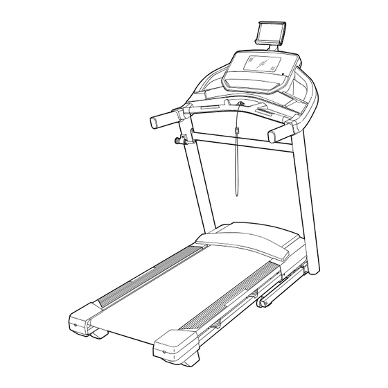
BEFORE YOU BEGIN Thank you for selecting the new PROFORM ® reading this manual, please see the front cover of this PERFORMANCE 400I treadmill. The PERFORMANCE manual. To help us assist you, note the product model 400I treadmill provides an impressive selection of fea- number and serial number before contacting us. -
Page 7: Part Identification Chart
PART IDENTIFICATION CHART Use the drawings below to identify small parts used for assembly. The number in parentheses below each draw- ing is the key number of the part, from the PART LIST near the end of this manual. The number following the key number is the quantity used for assembly. -
Page 8: Assembly
ASSEMBLY • Assembly requires two persons. • To identify small parts, see page 7. • Place all parts in a cleared area and remove the • Assembly requires the following tools: packing materials. Do not dispose of the packing the included hex keys materials until you fi... - Page 9 2. Make sure that the power cord is unplugged. Remove the tie securing the Upright Wire (80) to the front of the Base (88). Next, identify the Right Upright (79). Have a second person hold the Right Upright near the Base (88).
- Page 10 4. Set the Right Upright (79) on the Base (88) as shown. Make sure not to pinch the Upright Wire (80). Slide the Right Upright so that the 3/8" x 2 3/8" Screw (2) in the Base is inserted into the slot (E) in the Right Upright. Do not tighten the Screw yet.
- Page 11 6. Remove and save the four indicated 5/16" x 3/4" Screws (13). 7. Turn one of the Handrails (72) upside down. Insert a 5/16" x 1 1/2" Screw (5) with a 5/16" Star Washer (7) into the indicated large hole (F) and out of the indicated small hole (G).
- Page 12 9. Carefully slide the Upright Crossbar (77) between the Left and Right Uprights (78, 79). Attach the Upright Crossbar with the four 5/16" x 3/4" Screws (13) that you removed in step 6 7 13 and four 5/16" Star Washers (7); start all four Screws, and then tighten them.
- Page 13 11. IMPORTANT: To avoid damaging the Pulse Crossbar (75), do not use power tools and do not overtighten the #10 x 3/4" Screws (9). Orient the Pulse Crossbar (75) as shown. Attach the Pulse Crossbar to the Handrails (72) with four #10 x 3/4"...
- Page 14 13. Set the console assembly (K) on the Handrails (72). Make sure that no wires are pinched. Insert the excess Upright Wire (80) into the con- sole assembly (K). Then, tighten the two ties (M) around the Upright Wire and cut off the ends of the ties.
- Page 15 15. Slide the Right Handrail Cover (71) onto the right Handrail (72) and against the console assembly (K). Then, tighten a #8 x 3/4" Screw (11) into the bottom of the Right Handrail Cover. Do not overtighten the Screw. Attach the Left Handrail Cover (70) to the left Handrail (72) as described above.
- Page 16 17. Tighten the eight indicated Screws (2, 3, 4). 2, 3, 4 2, 3, 4 18. Press the two tabs on the Tablet Holder (91) into the slots (O) in the console assembly (K). Attach the Tablet Holder (91) with four M4 x 16mm Screws (90).
-
Page 17: How To Use The Treadmill
HOW TO USE THE TREADMILL HOW TO CONNECT THE POWER CORD more amps. To avoid overloading the circuit, do not plug other electrical devices, except for low- Use a Surge Suppressor power devices such as cell phone chargers, into the surge suppressor or into an outlet on the same Your treadmill, like other electronic equipment, can be circuit. - Page 18 CONSOLE DIAGRAM FEATURES OF THE CONSOLE In addition, the console features a selection of work- outs. Each workout automatically controls the speed The advanced treadmill console offers a selection of and incline of the treadmill as it guides you through an features designed to make your workouts more effec- effective exercise session.
- Page 19 HOW TO TURN ON THE POWER HOW TO USE THE TOUCH SCREEN IMPORTANT: If the treadmill has been exposed to The console features a tablet with a full-color touch cold temperatures, allow it to warm to room tem- screen. The following information will help you become perature before you turn on the power.
- Page 20 HOW TO SET UP THE CONSOLE 5. Check for firmware updates. Before using the treadmill for the first time, set up the First, touch your name on the screen and touch the console. gears button. Next, select the maintenance sec- tion.
- Page 21 HOW TO USE THE MANUAL MODE 4. Change the incline of the treadmill as desired. 1. Insert the key into the console. To change the incline of the treadmill, press the incline increase and decrease buttons or one of the See HOW TO TURN ON THE POWER on page numbered incline buttons.
- Page 22 • Your pace To measure your heart rate, stand on the foot rails and hold the contacts with your palms for • The speed of the walking belt approximately ten seconds; avoid moving your hands. When your pulse is detected, your heart •...
- Page 23 HOW TO USE A MAP WORKOUT 5. Monitor your progress with the display modes. Note: To use a map workout, the console must be con- See step 5 on page 21. nected to a wireless network (see HOW TO USE THE WIRELESS NETWORK MODE on page 27).
- Page 24 4. Save your workout. HOW TO USE A DISTANCE OR TIME WORKOUT Touch the Save New Workout button on the Note: To use a distance or time workout, the console screen. If desired, change the title of the workout or must be connected to a wireless network (see HOW add a description, and then press the >...
- Page 25 5. Select a distance or time workout that you have HOW TO USE THE WORKOUT SETTINGS SECTION previously added to your schedule on iFit.com. 1. Select the settings main menu. Touch the calendar icon to download a distance or time workout from your schedule. Insert the key into the console (see HOW TO TURN ON THE POWER on page 19).
- Page 26 HOW TO USE THE EQUIPMENT SETTINGS HOW TO USE THE MAINTENANCE SECTION SECTION 1. Select the settings main menu. 1. Select the settings main menu. See step 1 on page 25. See step 1 on page 25. 2. Select the maintenance section. 2.
- Page 27 4. Calibrate the incline system of the treadmill. Note: You must have your own wireless network and an 802.11b/g/n router with SSID broadcast Touch the Calibrate Incline button. Then, touch the enabled (hidden networks are not supported). Begin button to calibrate the incline system. The treadmill will automatically rise to the maximum When a list of networks appears, touch the desired incline level, lower to the minimum incline level,...
- Page 28 HOW TO USE THE SOUND SYSTEM HOW TO USE THE TABLET HOLDER To play music or audio books through the console IMPORTANT: The tablet holder (D) is designed sound system while you exercise, plug a 3.5 mm male for use with most full-size tablets. Do not place to 3.5 mm male audio cable (not included) into the jack any other electronic device or object in the tablet on the console and into a jack on your personal audio...
-
Page 29: How To Fold And Move The Treadmill
HOW TO FOLD AND MOVE THE TREADMILL HOW TO FOLD THE TREADMILL HOW TO MOVE THE TREADMILL To avoid damaging the treadmill, adjust the incline Before moving the treadmill, fold it as described at to zero before you fold the treadmill. Then, remove the left. -
Page 30: Maintenance And Troubleshooting
MAINTENANCE AND TROUBLESHOOTING MAINTENANCE c. Check the power switch located on the treadmill frame near the power cord. If the switch protrudes Regular maintenance is important for optimal per- as shown, the switch has tripped. To reset the formance and to reduce wear. Inspect and properly power switch, wait for five minutes and then press tighten all parts each time the treadmill is used. - Page 31 SYMPTOM: The incline of the treadmill does not c. Your treadmill features a walking belt coated with change correctly high-performance lubricant. IMPORTANT: Never apply silicone spray or other substances to a. Calibrate the incline system (see step 4 on the walking belt or the walking platform unless page 27).
- Page 32 SYMPTOM: The walking belt slips when walked on SYMPTOM: The displays of the console do not function properly a. First, remove the key and UNPLUG THE POWER CORD. Using the hex key, turn both idler roller a. If the console does not boot up properly, or screws clockwise, 1/4 of a turn.
-
Page 33: Exercise Guidelines
EXERCISE GUIDELINES Burning Fat—To burn fat effectively, you must exer- WARNING: cise at a low intensity level for a sustained period of Before beginning this time. During the first few minutes of exercise, your or any exercise program, consult your physi- body uses carbohydrate calories for energy. - Page 34 SUGGESTED STRETCHES The correct form for several basic stretches is shown at the right. Move slowly as you stretch —never bounce. 1. Toe Touch Stretch Stand with your knees bent slightly and slowly bend forward from your hips. Allow your back and shoulders to relax as you reach down toward your toes as far as possible.
-
Page 35: Part List
PART LIST Model No. PFTL59518.3 R0719A Key No. Qty. Description Key No. Qty. Description #8 x 1/2" Ground Screw 9/32" Plastic Bushing 3/8" x 2 3/8" Screw Controller Plate 3/8" x 1 1/4" Screw Plastic Tie 3/8" x 1 1/2" Screw Latch Plate 5/16"... -
Page 36: Exploded Drawing
EXPLODED DRAWING A Model No. PFTL59518.3 R0719A... - Page 37 EXPLODED DRAWING B Model No. PFTL59518.3 R0719A...
- Page 38 EXPLODED DRAWING C Model No. PFTL59518.3 R0719A 12 36...
- Page 39 EXPLODED DRAWING D Model No. PFTL59518.3 R0719A...
-
Page 40: Ordering Replacement Parts
ORDERING REPLACEMENT PARTS To order replacement parts, please see the front cover of this manual. To help us assist you, be prepared to provide the following information when contacting us: • the model number and serial number of the product (see the front cover of this manual) •...