Table of Contents
Advertisement
Quick Links
Advertisement
Table of Contents

Related Manuals for Supermicro X10DRL-LN4


Summary of Contents for Supermicro X10DRL-LN4
- Page 1 X10DRL-LN4 USER’S MANUAL Revision 1.0c...
- Page 2 This product, including software and docu- mentation, is the property of Supermicro and/or its licensors, and is supplied only under a license. Any use or reproduction of this product is not allowed, except as expressly permitted by the terms of said license.
- Page 3 (E5-2600v4) Processing Technology, delivering the best balanced solution of performance, power efficiency, and features to address the diverse needs of next- generation data centers. With the PCH C612 built in, the X10DRL-LN4 motherboard supports Intel® Management Engine, MCTP Protocol, and Node Manager 3.0.
- Page 4 X10DRL-LN4 Motherboard User’s Manual Conventions Used in the Manual Pay special attention to the following symbols for proper system installation: Warning: Important information given to ensure proper system installation or to prevent damage to the components or injury to yourself;...
- Page 5 Super Micro Computer, Inc. 980 Rock Ave. San Jose, CA 95131 U.S.A. Tel: +1 (408) 503-8000 Fax: +1 (408) 503-8008 Email: marketing@supermicro.com (General Information) support@supermicro.com (Technical Support) Website: www.supermicro.com Europe Address: Super Micro Computer B.V. Het Sterrenbeeld 28, 5215 ML...
-
Page 6: Table Of Contents
PC Health Monitoring ..................1-12 ACPI Features ....................1-13 Power Supply ....................1-13 Advanced Power Management ..............1-14 Intel Intelligent Power Node Manager (NM) (Available when "Supermicro ® Power Management (SPM)" is Installed) ............1-14 Management Engine (ME) ................1-14 Chapter 2 Installation Standardized Warning Statements .............. - Page 7 Table of Contents Front Control Panel Pin Definitions............... 2-23 NMI Button ....................2-23 Power LED ....................2-23 HDD LED/UID Switch ................2-24 NIC1/NIC2 LED Indicators ............... 2-24 Overheat (OH)/Fan Fail/PWR Fail/UID LED ..........2-25 Power Fail LED ..................2-25 Reset Button ................... 2-26 Power Button ...................
- Page 8 X10DRL-LN4 Motherboard User’s Manual Chapter 3 Troubleshooting Troubleshooting Procedures ................3-1 Technical Support Procedures ................ 3-4 Battery Removal and Installation ..............3-6 Frequently Asked Questions ................3-7 Returning Merchandise for Service..............3-9 Chapter 4 BIOS Introduction ...................... 4-1 Main Setup ...................... 4-2 Advanced Setup Configurations..............
-
Page 9: Chapter 1 Overview
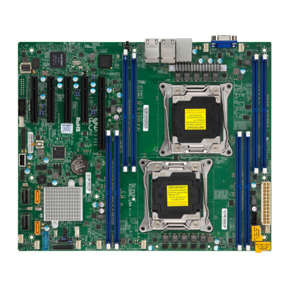
Checklist Congratulations on purchasing your computer motherboard from an acknowledged leader in the industry. Supermicro boards are designed with the utmost attention to detail to provide you with the highest standards in quality and performance. Please check that the following items have all been included with your motherboard. - Page 10 X10DRL-LN4 Motherboard User’s Manual X10DRL-LN4 Motherboard Image Note: All graphics shown in this manual were based upon the latest PCB Revision available at the time of publishing of the manual. The motherboard you've received may or may not look exactly the same as the graphics...
- Page 11 CTRL IPMI_LAN LAN3/4 LAN1/2 X10DRL-LN4 Rev. 1.00 CPU2 OPEN 1st BIOS LICENSE CLOSE 1st CPU1 Battery CLOSE 1st JSD2 JSD1 JBT1 OPEN 1st JWD1 JPWR1 Note: For the latest CPU/Memory updates, please refer to our website at http://www.supermicro.com/products/motherboard/ for details.
- Page 12 X10DRL-LN4 Motherboard User’s Manual X10DRL-LN4 Quick Reference JLAN2 JLAN1 USB0/1 LEDM1 CTRL IPMI_LAN LAN3/4 LAN1/2 X10DRL-LN4 Rev. 1.00 CPU2 OPEN 1st BIOS LICENSE CLOSE 1st CPU1 Battery CLOSE 1st JSD2 JSD1 JBT1 OPEN 1st JWD1 JPWR1 Notes: • See Chapter 2 for detailed information on jumpers, I/O ports and JF1 front panel connections.
- Page 13 Chapter 1: Overview X10DRL-LN4 Jumpers Jumper Description Default Setting JBT1 Clear CMOS Configuration (See Chapter 2) C1/JI SMB to PCI-E Slots Pins 2-3 (Disabled) JPB1 BMC Enable/Disable Pins 1-2 (Enabled) JPG1 VGA Enable/Disable Pins 1-2 (Enabled) JPL1 GLAN1/2 & GLAN3/4 Enable/Disable...
- Page 14 X10DRL-LN4 Motherboard User’s Manual (CPU2) Slot4 PCI-Express 3.0 x4 in x8 slot from CPU2 (CPU1) Slot5 PCI-Express 3.0 x16 slot from CPU1 Internal Speaker/Buzzer header UID (JUIDB1) Unit Identifier button (BP) USB 0/1 (2.0) Backpanel USB 2.0 connector for USB 0/1 (FP) USB 2 (2.0)
- Page 15 Registered (RDIMM)/Load Reduced (LRDIMM) 2400/2133/1866/1600 MHz in 8 slots Notes: 1. Memory speed support depends on the CPUs installed in the system. 2.. For the latest CPU/memory updates, please refer to our website at http://www.supermicro.com/ products/motherboard. DIMM sizes • DIMM...
- Page 16 Power-on mode for AC power recovery • Intel Intelligent Power Node Manager 3.0 (Avail- ® able when the Supermicro Power Management (SPM) is installed and special power supply used. See the note on Page 1-14.) • Management Engine (ME) PC Health PC Health/CPU Monitoring •...
- Page 17 Note 1: CPU Maximum Thermal Design Power (TDP) is subject to chassis and heatsink cooling restrictions. For proper thermal management, please check the chassis and heatsink specifications for proper CPU TDP sizing. Note 2: For IPMI Configuration Instructions, please refer to the Embedded IPMI Configuration User's Guide available at http://www.supermicro.com/ support/manuals/.
- Page 18 X10DRL-LN4 Motherboard User’s Manual X10DRL-LN4 #2-4 #1-4 5 Phase 5 Phase #2-3 #1-3 #2-2 145W 145W #1-2 #2-1 #1-1 9.6G 9.6G PCI-E X4 G3 PCI-E X16 G3 PCI-E X4 G2 LAN1~LAN4 i350 PCI-E X8 G3 PCI-E X8 G3 #6~9 DMI2...
-
Page 19: Processor And Chipset Overview
Processor and Chipset Overview Built upon the functionality and capability of the Intel E5-2600v3/v4 series proces- sors (Socket R3) and the Intel C612 PCH, the X10DRL-LN4 motherboard provides the best balanced solution of performance, power efficiency, and features to ad- dress the diverse needs of next-generation computer users. -
Page 20: Special Features
X10DRL-LN4 Motherboard User’s Manual Special Features Recovery from AC Power Loss The Basic I/O System (BIOS) provides a setting that determines how the system will respond when AC power is lost and then restored to the system. You can choose for the system to remain powered off (in which case you must press the power switch to turn it back on), or for it to automatically return to the power-on state. -
Page 21: Acpi Features
It is even more important for processors that have high CPU clock rates. The X10DRL-LN4 motherboard accommodates 24-pin ATX power supplies. Al- though most power supplies generally meet the specifications required by the CPU, some are inadequate. In addition, two 12V 8-pin power connections are also required to ensure adequate power supply to the system. -
Page 22: Advanced Power Management
The following new advanced power management features are supported by this motherboard: Intel Intelligent Power Node Manager (NM) (Available ® when "Supermicro Power Management (SPM)" is Installed) The Intel Intelligent Power Node Manager 3.0 (IPNM) provides your system with ®... -
Page 23: Chapter 2 Installation
The following statements are industry-standard warnings, provided to warn the user of situations which have the potential for bodily injury. Should you have questions or experience difficulty, contact Supermicro's Technical Support department for assis- tance. Only certified technicians should attempt to install or configure components. - Page 24 X10DRL-LN4 Motherboard User’s Manual Attention Danger d'explosion si la pile n'est pas remplacée correctement. Ne la remplacer que par une pile de type semblable ou équivalent, recommandée par le fabricant. Jeter les piles usagées conformément aux instructions du fabricant. ¡Advertencia! Existe peligro de explosión si la batería se reemplaza de manera incorrecta.
- Page 25 Chapter 2: Installation Product Disposal Warning! Ultimate disposal of this product should be handled according to all national laws and regulations. 製品の廃棄 この製品を廃棄処分する場合、 国の関係する全ての法律 ・ 条例に従い処理する必要が あります。 警告 本产品的废弃处理应根据所有国家的法律和规章进行。 警告 本產品的廢棄處理應根據所有國家的法律和規章進行。 Warnung Die Entsorgung dieses Produkts sollte gemäß allen Bestimmungen und Gesetzen des Landes erfolgen.
-
Page 26: Static-Sensitive Devices
X10DRL-LN4 Motherboard User’s Manual القىانين واللىائح الىطنية جميع وفقا ل ينبغي التعامل معه هذا المنتج من التخلص النهائي عند 경고! 이 제품은 해당 국가의 관련 법규 및 규정에 따라 폐기되어야 합니다. Waarschuwing De uiteindelijke verwijdering van dit product dient te geschieden in overeenstemming met alle nationale wetten en reglementen. -
Page 27: Processor And Heatsink Installation
CPU socket cap is in place and none of the socket pins are bent; otherwise, contact your retailer immediately. Refer to the Supermicro website for updates on CPU support. Installing the LGA2011 Processor 1. There are two load levers on the LGA2011 socket. To open the socket cover, first press and release the load lever labeled 'Open 1st'. - Page 28 X10DRL-LN4 Motherboard User’s Manual 2. Press the second load lever labeled 'Close 1st' to release the load plate that covers the CPU socket from its locking position. Pull lever away from Press down on Load the socket Lever 'Close 1st' 3.
- Page 29 Chapter 2: Installation 4. Use your thumb and the index finger to loosen the lever and open the load plate. 5. Using your thumb and index finger, hold the CPU on its edges. Align the CPU keys, which are semi-circle cutouts, against the socket keys. Socket Keys CPU Keys Warning: You can only install the CPU...
- Page 30 X10DRL-LN4 Motherboard User’s Manual 6. Once they are aligned, carefully lower the CPU straight down into the socket. (Do not drop the CPU on the socket. Do not move the CPU horizontally or vertically. Do not rub the CPU against the surface or against any pins of the socket to avoid damaging the CPU or the socket.)
-
Page 31: Installing A Passive Cpu Heatsink
Chapter 2: Installation Installing a Passive CPU Heatsink 1. Do not apply any thermal grease to the heatsink or the CPU die -- the re- quired amount has already been applied. 2. Place the heatsink on top of the CPU so that the four mounting holes are aligned with those on the motherboard and the heatsink bracket underneath. -
Page 32: Removing The Heatsink
X10DRL-LN4 Motherboard User’s Manual Removing the Heatsink Warning: We do not recommend that the CPU or the heatsink be removed. However, if you do need to remove the heatsink, please follow the instructions below to uninstall the heatsink to prevent damage done to the CPU or the CPU socket. -
Page 33: Installing And Removing The Memory Modules
Chapter 2: Installation Installing and Removing the Memory Modules Note: Check Supermicro's website for recommended memory modules. CAUTION Exercise extreme care when installing or removing DIMM modules to prevent any possible damage. Installing & Removing DIMMs 1. Insert the desired number of DIMMs into the memory slots, starting with P1-DIMM A1. -
Page 34: Dimm Module Removal
X10DRL-LN4 Motherboard User’s Manual DIMM Module Removal Press the release tabs on both ends of the DIMM socket to release the DIMM module from the socket as shown in the drawing on the right. Warnings: 1. Please do not use excessive force when pressing the release tabs on the ends of the DIMM socket to avoid causing any damage to the DIMM module or the DIMM socket. - Page 35 Chapter 2: Installation Memory Support for the X10DRL-LN4 Motherboard The X10DRL-LN4 Motherboard supports up to 1 TB of ECC DDR4 3DS LRDIMM or 512 GB of ECC DDR4 Registered (RDIMM)/Load Reduced (LRDIMM) 2400/2133/1866/1600 MHz in eight DIMM slots. Memory speed support is pending on the processors used in the system.
- Page 36 X10DRL-LN4 Motherboard User’s Manual Populating RDIMM/LRDIMM DDR4 Memory Modules for the E5- 2600V3/v4-based Motherboard Populating RDIMM/LRDIMM DDR4 Memory Modules Speed (MT/s); Voltage (V); Slots per Channel (SPC) and DIMMs per Channel (DPC) Ranks DIMM Capacity Per DIMM 1 Slot per Channel (1DPC)
-
Page 37: Motherboard Installation
• Standoffs (8 pieces, if needed) Location of Mounting Holes There are eight (8) mounting holes on this motherboard indicated by the arrows. X10DRL-LN4 Rev. 1.00 BIOS LICENSE Caution: 1) To avoid damaging the motherboard and its components, please do not use a force greater than 8 lb/inch on each mounting screw during motherboard installation. -
Page 38: Installing The Motherboard
X10DRL-LN4 Motherboard User’s Manual Installing the Motherboard 1. Install the I/O shield into the chassis. 2. Locate the mounting holes on the motherboard. 3. Locate the matching mounting holes on the chassis. Align the mounting holes on the motherboard against the mounting holes on the chassis. -
Page 39: Control Panel Connectors And I/O Ports
Control Panel Connectors and I/O Ports The I/O ports are color coded in conformance with the industry standards. See the picture below for the colors and locations of the various I/O ports. Back Panel Connectors and I/O Ports X10DRL-LN4 Rev. 1.00 BIOS LICENSE Back Panel I/O Port Locations and Definitions 1. -
Page 40: Serial Port
X10DRL-LN4 Motherboard User’s Manual Serial Port Serial (COM) Port Pin Definitions A COM port header (COM1), located Pin # Definition Pin # Definition next to PCH PCI-E Slot1, provides front-accessible serial port support on the motherboard. See the table on the right for pin definitions. -
Page 41: Universal Serial Bus (Usb)
1. Backpanel USB0 (USB2.0) JLAN2 JLAN1 USB0/1 2. Backpanel USB1 (USB2.0) LEDM1 CTRL IPMI_LAN LAN3/4 LAN1/2 X10DRL-LN4 3. FP USB 3/4 (USB2.0) Rev. 1.00 CPU2 4. FP USB 2 (USB2.0) OPEN 1st 5. FP USB 5/6 (USB 3.0) BIOS LICENSE CLOSE 1st... -
Page 42: Ethernet Ports
X10DRL-LN4 Motherboard User’s Manual Ethernet Ports LAN Ports Pin Definition Four Gigabit Ethernet ports (LAN1/2, Pin# Definition Pin# Definition LAN3/4) are located on the I/O Ground TD1+ backpanel on the motherboard. These TD1- ethernet ports are supported by the In-... -
Page 43: Unit Identifier Switch/Uid Led Indicator
Power Button Ground JLAN2 JLAN1 USB0/1 1. UID Switch LEDM1 CTRL IPMI_LAN LAN3/4 LAN1/2 2. Rear UID LED X10DRL-LN4 Rev. 1.00 CPU2 3. Front UID LED OPEN 1st 4. Front UID Switch BIOS LICENSE CLOSE 1st CPU1 Battery CLOSE 1st... -
Page 44: Front Control Panel
These connectors are designed specifically for use with Supermicro's server chassis. See the figure below for the descriptions of the various control panel buttons and LED indicators. Refer to the following section for descriptions and pin definitions. -
Page 45: Front Control Panel Pin Definitions
PWR LED A. NMI B. PWR LED JLAN2 JLAN1 USB0/1 Ground LEDM1 CTRL IPMI_LAN LAN3/4 LAN1/2 X10DRL-LN4 Rev. 1.00 CPU2 3.3 V FP PWRLED OPEN 1st UID Switch HDD LED BIOS LICENSE NIC1 Link LED NIC1 Activity LED CLOSE 1st... -
Page 46: Hdd Led/Uid Switch
X10DRL-LN4 Motherboard User’s Manual HDD LED/UID Switch HDD LED/UID Switch Pin Definitions (JF1) The HDD LED/UID Switch connection Pin# Definition is located on pins 13 and 14 of JF1. UID Switch Attach a cable to Pin 14 to show HDD HD Active activity status. -
Page 47: Overheat (Oh)/Fan Fail/Pwr Fail/Uid Led
A. OH/Fail/PWR Fail LED/UID LED B. PWR Supply Fail JLAN2 JLAN1 USB0/1 Ground LEDM1 CTRL IPMI_LAN LAN3/4 LAN1/2 X10DRL-LN4 Rev. 1.00 CPU2 FP PWRLED 3.3 V OPEN 1st HDD LED UID Switch BIOS LICENSE NIC1 Link LED NIC1 Activity LED... -
Page 48: Reset Button
X10DRL-LN4 Motherboard User’s Manual Reset Button Reset Button Pin Definitions (JF1) The reset button is located on pins 3 and Pin# Definition 4 of JF1. Attach it to a hardware reset Reset switch on the computer case. Refer to Ground the table on the right for pin definitions. -
Page 49: Connecting Cables
A. J24: 24-pin ATX PWR JLAN2 JLAN1 USB0/1 (Req'd) B. JPWR1: 8-pin Proces- CTRL LEDM1 IPMI_LAN LAN3/4 LAN1/2 sor PWR (Req'd) X10DRL-LN4 Rev. 1.00 CPU2 C. JPWR2: 8-pin Proces- OPEN 1st sor PWR (Req'd) BIOS LICENSE CLOSE 1st CPU1 Battery CLOSE 1st... -
Page 50: Fan Headers
X10DRL-LN4 Motherboard User’s Manual Fan Headers Fan Header Pin Definitions This motherboard has eight system/CPU Pin# Definition fan headers (Fan 1-Fan 6, Fan A, and Fan Ground B) on the motherboard. All these 4-pin +12V fans headers are backward compatible Tachometer with the traditional 3-pin fans. -
Page 51: Internal Speaker
Serial Link DOM devices. A. Internal Speaker JLAN2 JLAN1 USB0/1 (Buzzer) B. SATA DOM PWR CTRL LEDM1 IPMI_LAN LAN3/4 LAN1/2 X10DRL-LN4 (JSD1) Rev. 1.00 CPU2 C. SATA DOM PWR OPEN 1st (JSD2) BIOS LICENSE CLOSE 1st CPU1 Battery CLOSE 1st... -
Page 52: Tpm/Port 80 Header
X10DRL-LN4 Motherboard User’s Manual TPM/Port 80 Header TPM/Port 80 Header Pin Definitions A Trusted Platform Module/Port 80 Pin # Definition Pin # Definition header is located at JTPM1 to provide LCLK TPM support and Port 80 connection. LFRAME# <(KEY)> Use this header to enhance system... -
Page 53: Power Smb (I 2 C) Connector
C connection on your Clock system. No Connection A. JPI JLAN2 JLAN1 USB0/1 B. JIPMB1 LEDM1 CTRL IPMI_LAN LAN3/4 LAN1/2 X10DRL-LN4 Rev. 1.00 CPU2 OPEN 1st BIOS LICENSE CLOSE 1st CPU1 Battery CLOSE 1st JSD2 JSD1 JBT1 OPEN 1st JWD1... -
Page 54: I-Sgpio 1 Header
X10DRL-LN4 Motherboard User’s Manual I-SGPIO 1 Header I-SGPIO Header Pin Definitions An SGPIO (Serial Link General Pur- Pin# Definition Pin# Definition pose Input/Output) header is located on the motherboard. I-SGPIO1 sup- Ground Data ports onboard I-SATA4 and I-SATA5. Load Ground... -
Page 55: Power Led/Speaker
Pin 5 No Connection Pin 6 R_SPKRIN_N Pin 7 R_SPKRIN A. PWR LED/Speaker JLAN2 JLAN1 USB0/1 LEDM1 CTRL IPMI_LAN LAN3/4 LAN1/2 X10DRL-LN4 Rev. 1.00 CPU2 OPEN 1st BIOS LICENSE CLOSE 1st CPU1 Battery CLOSE 1st JSD2 JSD1 JBT1 OPEN 1st JWD1... -
Page 56: Jumper Settings
X10DRL-LN4 Motherboard User’s Manual Jumper Settings Explanation of Jumpers Connector Pins To modify the operation of the mother- board, jumpers can be used to choose between optional settings. Jumpers create Jumper shorts between two pins to change the function of the connector. Pin 1 is identified with a square solder pad on the printed circuit board. -
Page 57: Cmos Clear
Watch Dog must also be enabled in the BIOS. A. Clear CMOS JLAN2 JLAN1 USB0/1 B. Watch Dog Enable LEDM1 CTRL IPMI_LAN LAN3/4 LAN1/2 X10DRL-LN4 Rev. 1.00 CPU2 OPEN 1st BIOS LICENSE CLOSE 1st CPU1 Battery CLOSE 1st JSD2 JSD1... -
Page 58: Vga Enable/Disable
X10DRL-LN4 Motherboard User’s Manual VGA Enable/Disable VGA Enable Jumper Settings Jumper JPG1 allows the user to enable Jumper Setting Definition or disable the onboard VGA connector. Enabled (Default) The default setting is 1-2 to enable the Disabled connection. See the table on the right for jumper settings. -
Page 59: I 2 C Bus To Pci-Exp. Slots
See the table on the right for jumper settings. A. JI JLAN2 JLAN1 USB0/1 B. JI LEDM1 CTRL C. ME Select IPMI_LAN LAN3/4 LAN1/2 X10DRL-LN4 Rev. 1.00 CPU2 OPEN 1st BIOS LICENSE CLOSE 1st CPU1 Battery CLOSE 1st JSD2 JSD1 JBT1... -
Page 60: Onboard Led Indicators
X10DRL-LN4 Motherboard User’s Manual Onboard LED Indicators LAN1/2/3/4 & IPMI_LAN LEDs Four LAN ports (LAN1/2/3/4), and an IPMI_ dedicated_ LAN are located on the IO back panel of the motherboard. LAN1/2/3/4 are supported by the onboard Intel LAN controller, and IPMI_LAN is supported by the BMC. Each Ethernet LAN port has two LEDs. -
Page 61: Onboard Power Led
See the table at right for more information. A. PWR LED JLAN2 JLAN1 USB0/1 B . P W R G O O D LEDM1 CTRL IPMI_LAN LAN3/4 LAN1/2 X10DRL-LN4 Rev. 1.00 CPU2 OPEN 1st BIOS LICENSE CLOSE 1st CPU1 Battery CLOSE 1st JSD2 JSD1... -
Page 62: Bmc Heartbeat Led
X10DRL-LN4 Motherboard User’s Manual BMC Heartbeat LED BMC Heartbeat LED States A BMC Heartbeat LED is located at Color/State Definition LEDM1 on the motherboard. When Green: BMC: Normal LEDM1 is blinking, BMC functions nor- Blinking mally. See the table at right for more information. -
Page 63: 2-10 Sata Connections
Intel PCH, and S-SATA0-3 are SATA_TXP supported by the Intel SCU. I-SATA4/5 can be used SATA_TXN with Supermicro SuperDOMs which are yellow SATA Ground DOM connectors with power pins built in, and do not SATA_RXN require external cables. Supermicro SuperDOMs are... - Page 64 X10DRL-LN4 Motherboard User’s Manual Notes 2-42...
-
Page 65: Chapter 3 Troubleshooting
Chapter 3: Troubleshooting Chapter 3 Troubleshooting Troubleshooting Procedures Use the following procedures to troubleshoot your system. If you have followed all of the procedures below and still need assistance, refer to the ‘Technical Support Procedures’ and/or ‘Returning Merchandise for Service’ section(s) in this chapter. Note: Always disconnect the power cord before adding, changing or installing any hardware components. - Page 66 X10DRL-LN4 Motherboard User’s Manual No Video 1. If the power is on, but you have no video, remove all the add-on cards and cables. 2. Use the speaker to determine if any beep codes exist. Refer to Appendix A for details on beep codes.
- Page 67 2. Memory support: Make sure that the memory modules are supported by test- ing the modules using memtest86 or a similar utility. Note: Refer to the product page on our website http:\\www.supermicro. com for memory and CPU support and updates.
-
Page 68: Technical Support Procedures
You can also install the component in question in another system. If the new system works, the component is good and the old system has problems. Technical Support Procedures Before contacting Technical Support, please take the following steps. Also, please note that as a motherboard manufacturer, Supermicro also sells motherboards... - Page 69 1. Please go through the ‘Troubleshooting Procedures’ and 'Frequently Asked Question' (FAQ) sections in this chapter or see the FAQs on our website (http://www.supermicro.com/) before contacting Technical Support. 2. BIOS upgrades can be downloaded from our website (http://www.supermicro.
-
Page 70: Battery Removal And Installation
X10DRL-LN4 Motherboard User’s Manual Battery Removal and Installation Battery Removal To remove the onboard battery, follow the steps below: 1. Power off your system and unplug your power cable. 2. Locate the onboard battery as shown below. 3. Using a tool such as a pen or a small screwdriver, push the battery lock out- wards to unlock it. -
Page 71: Frequently Asked Questions
Note: The SPI BIOS chip used on this motherboard cannot be removed. Send your motherboard back to our RMA Department at Supermicro for repair. For BIOS Recovery instructions, please refer to the AMI BIOS Recovery Instructions posted at http://www.supermicro.com. - Page 72 X10DRL-LN4 Motherboard User’s Manual 3. Insert the USB stick into a USB port, boot to the UEFI Built-In Shell, and type the following commands to start the BIOS update: Shell> fs0: fs0:\> cd UEFI fs0:\UEFI> flash.nsh BIOSname#.### 4. The FLASH.NSH script will compare the Flash Descriptor Table (FDT) code in the new BIOS with the existing one in the motherboard: a.
-
Page 73: Returning Merchandise For Service
Shipping and handling charges will be applied for all orders that must be mailed when service is complete. For faster service, You can also request a RMA authorization online (http://www.supermicro.com/RmaForm/). This warranty only covers normal consumer use and does not cover any damage incurred in shipping or from failure due to the alternation, misuse, abuse or improper maintenance of products. - Page 74 X10DRL-LN4 Motherboard User’s Manual Notes 3-10...
-
Page 75: Chapter 4 Bios
BIOS Introduction This chapter describes the AMI BIOS setup utility for the X10DRL-LN4. The ROM BIOS is stored in a Flash EEPROM and can be easily updated. This chapter de- scribes the basic navigation of the AMI BIOS setup utility screens. -
Page 76: Main Setup
Flashing the wrong BIOS can cause irreparable damage to the system. In no event shall Supermicro be liable for direct, indirect, special, incidental, or consequential damages arising from a BIOS update. If you have to update the BIOS, do not shut down or reset the system while the BIOS is updating to avoid possible boot failure. - Page 77 Day MM/DD/YYYY format. The time is entered in HH:MM:SS format. Note: The time is in the 24-hour format. For example, 5:30 P.M. appears as 17:30:00. Supermicro X10DRL-LN4 BIOS Version: This item displays the version of the BIOS ROM used in the system.
-
Page 78: Advanced Setup Configurations
X10DRL-LN4 Motherboard User’s Manual Advanced Setup Configurations Use the arrow keys to select Advanced setup and press <Enter> to access the submenu items: Warning: Take Caution when changing the Advanced settings. A wrong value, an incorrect DRAM frequency, or an improper BIOS setting may cause the system to malfunction. - Page 79 Chapter 4: AMI BIOS Wait For 'F1' If Error Select Enabled to force the system to wait until the 'F1' key is pressed if an error occurs. The options are Disabled and Enabled. INT19 (Interrupt 19) Trap Response Interrupt 19 is the software interrupt that handles the boot disk function. When this item is set to Immediate, the ROM BIOS of the host adaptors will "capture"...
- Page 80 X10DRL-LN4 Motherboard User’s Manual CPU Configuration This submenu displays the following CPU information as detected by the BIOS. It also allows the user to configure CPU settings. CPU1/CPU2 This submenu displays the following information of the CPU installed in CPU1 and CPU2.
- Page 81 Chapter 4: AMI BIOS Execute-Disable Bit (Available if supported by the OS & the CPU) Select Enable for Execute Disable Bit Technology support, which will allow the processor to designate areas in the system memory where an application code can execute and where it cannot, thus preventing a worm or a virus from flooding illegal codes to overwhelm the processor to damage the system during an attack.
- Page 82 X10DRL-LN4 Motherboard User’s Manual X2 APIC (Advanced Programmable Interrupt Controller) Based on Intel's Hyper-Threading architecture, each logical processor (thread) is assigned 256 APIC IDs (APIDs) in 8-bit bandwidth. When this feature is set to En- able, the APIC ID will be expanded (X2) from 8 bits to 16 bits to provide 512 APIDs to each thread to enhance CPU performance.
- Page 83 Chapter 4: AMI BIOS Energy Efficiency Turbo Select Enable for the system to operate at turbo mode with reduced power con- sumption so that your machine can achieve maximum system performance with the maximum power efficiency possible. The options are Enable and Disable. *If the item-"Power Technology"...
- Page 84 X10DRL-LN4 Motherboard User’s Manual CPU C State Control (Available when Power Technology is set to Custom) Package C State limit Use this item to set the limit on the C-State package register. The options are C0/1 state, C2 state, C6 (non-Retention) state, and C6 (Retention) state.
- Page 85 Chapter 4: AMI BIOS Chipset Configuration Warning! Please set the correct settings for the items below. A wrong configuration setting may cause the system to become malfunction. North Bridge This feature allows the user to configure the settings for the Intel North Bridge. IIO Configuration EV DFX (Device Function On-Hide) Feature When this feature is set to Enable, the EV_DFX Lock Bits that are located on a...
- Page 86 X10DRL-LN4 Motherboard User’s Manual IIO1 PORT 2C Link Speed This item configures the link speed for a PCI-E port specified by the user. The options are Gen 1 (2.5GT/s), Gen 2 (5 GT/s), and Gen 3 (8GT/s). IIO1 PORT 2D Link Speed This item configures the link speed for a PCI-E port specified by the user.
- Page 87 Chapter 4: AMI BIOS IOAT (Intel® IO Acceleration) Configuration Enable IOAT Select Enable to enable Intel I/OAT (I/O Acceleration Technology) support, which significantly reduces CPU overhead by leveraging CPU architectural improve- ments and freeing the system resource for other tasks. The options are Enable and Disable.
- Page 88 X10DRL-LN4 Motherboard User’s Manual • Current QPI Link Frequency • QPI Global MMIO Low Base/Limit • QPI Global MMIO High Base/Limit • QPI PCIe Configuration Base/Size Link Frequency Select Use this item to select the desired frequency for QPI Link connections. The op- tions are 6.4GB/s, 8.0GB/s, 9.6GB/s, Auto, and Auto Limited.
- Page 89 Chapter 4: AMI BIOS Memory Configuration Enforce POR Select Enable to enforce POR restrictions on DDR4 frequency and voltage programming. The options are Enabled and Disabled. Memory Frequency Use this feature to set the maximum memory frequency for onboard memory modules.
- Page 90 X10DRL-LN4 Motherboard User’s Manual Memory RAS (Reliability_Availability_Serviceability) Configuration Use this submenu to configure the following Memory RAS settings. RAS Mode When Independent is selected, all memory channels will operate independently. When Mirror is selected, the motherboard maintains two identical copies of all data in memory for data backup.
- Page 91 Chapter 4: AMI BIOS South Bridge Configuration The following South Bridge information will display: USB Configuration • USB Module Version • USB Controllers • USB Devices Legacy USB Support Select Enabled to support onboard legacy USB devices. Select Auto to disable legacy support if there are no legacy USB devices present.
- Page 92 X10DRL-LN4 Motherboard User’s Manual EHCI2 Select Enabled to enable EHCI (Enhanced Host Controller Interface) support on USB 2.0 connector #2 (-at least one USB 2.0 connector should be enabled for EHCI support.) The options are Disabled and Enabled. XHCI Pre-Boot Drive Select Enabled to enable XHCI (Extensible Host Controller Interface) support on a pre-boot drive specified by the user.
- Page 93 Chapter 4: AMI BIOS SATA Configuration When this submenu is selected, AMI BIOS automatically detects the presence of the SATA devices that are supported by the Intel PCH chip and displays the fol- lowing items: SATA Controller This item enables or disables the onboard SATA controller supported by the Intel PCH chip.
- Page 94 X10DRL-LN4 Motherboard User’s Manual Port 0 ~ Port 5 SATA Device Type Use this item to specify if the SATA port specified by the user should be con- nected to a Solid State drive or a Hard Disk Drive. The options are Hard Disk Drive and Solid State Drive.
- Page 95 Chapter 4: AMI BIOS SATA Port 0~ Port 5 Select Enabled to enable a SATA port specified by the user. The options are Disabled and Enabled. Port 0 ~ Port 5 Hot Plug Select Enabled to enable hot-plugging support for a port specified by the user, which will allow the user to replace a SATA disk drive installed on this port without shutting down the system.
- Page 96 X10DRL-LN4 Motherboard User’s Manual sSATA Port 0~ Port 3 This item displays the information detected on the installed on the sSATA port. specified by the user. • Model number of drive and capacity • Software Preserve Support sSATA Port 0~ Port 3 Select Enabled to enable an sSATA port specified by the user.
- Page 97 Chapter 4: AMI BIOS Support Aggressive Link Power Management When this item is set to Enabled, the SATA AHCI controller manages the power usage of the SATA link. The controller will put the link to a low power state when the I/O is inactive for an extended period of time, and the power state will return to normal when the I/O becomes active.
- Page 98 X10DRL-LN4 Motherboard User’s Manual Server ME (Management Engine) Configuration This feature displays the following system ME configuration settings. • General ME Configuration • Operational Firmware Version • ME Firmware Type • Recovery Firmware Version • ME Firmware Features • ME Firmware Status #1 •...
- Page 99 Chapter 4: AMI BIOS Maximum Payload Select Auto for the system BIOS to automatically set the maximum payload value for a PCI-E device to enhance system performance. The options are Auto, 128 Bytes, and 256 Bytes. Maximum Read Request Select Auto for the system BIOS to automatically set the maximum size for a read request for a PCI-E device to enhance system performance.
- Page 100 X10DRL-LN4 Motherboard User’s Manual VGA Priority Use this item to select the graphics device to be used as the primary video display for system boot. The options are Onboard and Offboard. Network Stack Select Enabled to enable PXE (Preboot Execution Environment) or UEFI (Uni- fied Extensible Firmware Interface) for network stack support.
- Page 101 Chapter 4: AMI BIOS Serial Port Console Redirection COM 1 COM 1 Console Redirection Select Enabled to enable COM Port 1 Console Redirection, which will allow a client machine to be connected to a host machine at a remote site for networking. The options are Disabled and Enabled.
- Page 102 X10DRL-LN4 Motherboard User’s Manual Flow Control Use this item to set the flow control for Console Redirection to prevent data loss caused by buffer overflow. Send a "Stop" signal to stop sending data when the receiving buffer is full. Send a "Start" signal to start sending data when the receiving buffer is empty.
- Page 103 Chapter 4: AMI BIOS SOL Console Redirection Settings Use this feature to specify how the host computer will exchange data with the client computer, which is the remote computer used by the user. Terminal Type Use this feature to select the target terminal emulation type for Console Redirec- tion.
- Page 104 X10DRL-LN4 Motherboard User’s Manual VT-UTF8 Combo Key Support Select Enabled to enable VT-UTF8 Combination Key support for ANSI/VT100 terminals. The options are Enabled and Disabled. Recorder Mode Select Enabled to capture the data displayed on a terminal and send it as text messages to a remote server.
- Page 105 Chapter 4: AMI BIOS EMS Console Redirection Settings This feature allows the user to specify how the host computer will exchange data with the client computer, which is the remote computer used by the user. Out-of-Band Management Port The feature selects a serial port in a client server to be used by the Windows Emergency Management Services (EMS) to communicate with a remote host server.
- Page 106 X10DRL-LN4 Motherboard User’s Manual High Precision Timer Select Enabled to activate the High Precision Event Timer (HPET) that produces periodic interrupts at a much higher frequency than a Real-time Clock (RTC) does in synchronizing multimedia streams, providing smooth playback and reducing the de- pendency on other timestamp calculation devices, such as an x86 RDTSC Instruc- tion embedded in the CPU.
- Page 107 EV DFX (Device Function On-Hide) support for the system to work prop- erly. (EV DFX is under "IIO Configuration" in the "Chipset/North Bridge" submenu on Page 4-11). Note: For more information on TPM, please refer to the TPM manual at http://www.supermicro.com/manuals/other/TPM.pdf. 4-33...
- Page 108 X10DRL-LN4 Motherboard User’s Manual iSCSI Configuration This item displays iSCSI configuration information: iSCSI Initiator Name Use this item to enter the name of the iSCSI Initiator, which is a unique name used in the world. The name must in the IQN format. The following submenu will be available for configuration: ...
-
Page 109: Event Logs
Chapter 4: AMI BIOS Event Logs Use this feature to configure Event Log settings. Change SMBIOS Event Log Settings This feature allows the user to configure SMBIOS Event settings. Enabling/Disabling Options SMBIOS Event Log Select Enabled to enable SMBIOS (System Management BIOS) Event Logging during system boot. - Page 110 X10DRL-LN4 Motherboard User’s Manual SMBIOS Event Log Standard Settings Log System Boot Event Select Enabled to log system boot events. The options are Disabled and Enabled. MECI (Multiple Event Count Increment) Enter the increment value for the multiple event counter. Enter a number between 1 to 255.
-
Page 111: Ipmi
Chapter 4: AMI BIOS IPMI Use this feature to configure Intelligent Platform Management Interface (IPMI) settings. IPMI Firmware Revision This item indicates the IPMI firmware revision used in your system. IPMI Status This item indicates the status of the IPMI firmware installed in your system. System Event Log ... - Page 112 X10DRL-LN4 Motherboard User’s Manual When SEL is Full This feature allows the user to determine what the BIOS should do when the sys- tem event log is full. Select Erase Immediately to erase all events in the log when the system event log is full. The options are Do Nothing and Erase Immediately.
-
Page 113: Security Settings
Chapter 4: AMI BIOS VLAN Select Enable for VLAN support. The default setting is Disable. Security Settings This menu allows the user to configure the following security settings for the system. Password Check Select Setup for the system to prompt for a password at Setup. Select Always for the system to prompt for a password at bootup and upon entering the BIOS Setup utility. - Page 114 X10DRL-LN4 Motherboard User’s Manual • Vendor Keys Secure Boot Select Enable for secure boot support to ensure system security at bootup. The options are Disabled and Enabled. Secure Boot Mode Select Customer to customize secure boot settings for your system to ensure system security at bootup.
- Page 115 Chapter 4: AMI BIOS Authorized Signatures Delete DB (DataBase) Select <Yes> to confirm deletion of a database from the your system. Set New DB (DataBase) Select <Yes> to confirm that a new DB from the factory defaults will be set in the system.
-
Page 116: Boot Settings
X10DRL-LN4 Motherboard User’s Manual Boot Settings Use this feature to configure Boot Settings: Boot Configuration Setup Prompt Timeout Use this item to indicate how many seconds the system shall wait for the BIOS setup activation key to respond before the system starts to boot. The default setting is 1. - Page 117 Chapter 4: AMI BIOS • When the item above -"Boot Mode Select" is set to UEFI, the following items will be display for configuration: UEFI Boot Order #1 - UEFI Boot Order #8 Delete Boot Option Use this item to select a boot device to delete from the boot priority list. Delete Boot Option Select the target boot device to delete from the boot priority list.
-
Page 118: Save & Exit
X10DRL-LN4 Motherboard User’s Manual Save & Exit Select the Save & Exit tab from the BIOS setup screen to configure the settings below. Discard Changes and Exit Select this option to quit the BIOS setup without making any permanent changes to the system configuration, and reboot the computer. - Page 119 Chapter 4: AMI BIOS Restore Optimized Defaults To set this feature, select Restore Defaults from the Exit menu and press <Enter>. These are manufacture default settings designed for maximum system performance but not for maximum stability. Save as User Defaults To set this feature, select Save as User Defaults from the Exit menu and press <En- ter>.
- Page 120 X10DRL-LN4 Motherboard User’s Manual Notes 4-46...
-
Page 121: Appendix A Bios Error Beep Codes
Appendix A: BIOS POST Error Codes Appendix A BIOS Error Beep Codes During the POST (Power-On Self-Test) routines, which are performed at each system boot, errors may occur. Non-fatal errors are those which, in most cases, allow the system to continue to boot. - Page 122 X10DRL-LN4 Motherboard User’s Manual Notes...
-
Page 123: Appendix B Software Installation Instructions
Appendix B Software Installation Instructions B-1 Installing Software Programs The Supermicro website that contains drivers and utilities for your system is located at http://www.supermicro.com/wftp. Some of these must be installed, such as the chipset driver. After accessing the product drivers and utilities page, go into the CDR_Images directory and locate the ISO file for your motherboard. -
Page 124: Installing Superdoctor® 5
B-2 Installing SuperDoctor ® The Supermicro SuperDoctor 5 is a hardware monitoring program that functions in a command-line or web-based interface in Windows and Linux operating systems. The program monitors system health information such as CPU temperature, system voltages, system power consumption, fan speed, and provides alerts via email or Simple Network Management Protocol (SNMP). -
Page 125: Logging Into The Bmc (Baseboard Management Controller
When logging in to the BMC for the first time, please use the unique password provided by Supermicro to log in. You can change the unique password to a user name and password of your choice for subsequent logins. - Page 126 X10DRL-LN4 Motherboard User’s Manual Notes...
-
Page 127: Appendix C Uefi Bios Recovery Instructions
Flashing the wrong BIOS can cause irreparable damage to the system. In no event shall Supermicro be liable for direct, indirect, special, incidental, or consequential damages arising from a BIOS update. If you need to update the BIOS, do not shut down or reset the system while the BIOS is updating to avoid possible boot failure. - Page 128 "\" directory of a USB device or a writeable CD/DVD. Note: If you cannot locate the "Super.ROM" file in your driver disk, visit our website at www.supermicro.com to download the BIOS image into a USB flash device and rename it "Super.ROM" for BIOS recovery use.
- Page 129 Appendix C: UEFI BIOS Recovery 4. After locating the new BIOS binary image, the system will enter the BIOS recovery menu as shown below. Note: At this point, you may decide if you want to start with BIOS recovery. If you decide to proceed with BIOS recovery, follow the procedures below. 5.
- Page 130 X10DRL-LN4 User’s Manual 6. After the process of BIOS recovery is completed, press any key to reboot the system. 7. Using a different system, extract the BIOS package into a bootable USB flash drive. 8. When a DOS prompt appears, enter FLASH.BAT BIOSname.### at the prompt.
- Page 131 (Disclaimer Continued) The products sold by Supermicro are not intended for and will not be used in life support systems, medical equipment, nuclear facilities or systems, aircraft, aircraft devices, aircraft/emergency com- munication devices or other critical systems whose failure to perform be reasonably expected to result in significant injury or loss of life or catastrophic property damage.