Advertisement
Quick Links
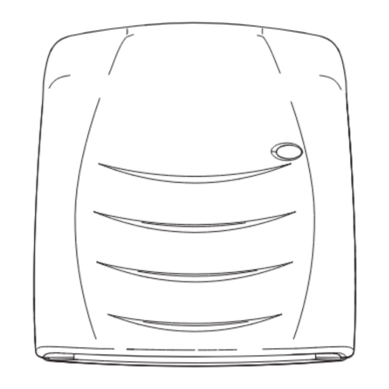
Downflow Fan Heater
Model : FX 20 IPX4
Dimensions
(millimetres)
Model(s)
Specification
(High Level) 1/2kw + Adjustable Thermostat (internal by installer)
FX 20 IPX4
THESE INSTRUCTIONS SHOULD BE READ CAREFULLY AND RETAINED FOR FUTURE REFERENCE
IMPORTANT SAFETY ADVICE
WARNING - DO NOT USE THIS HEATER IN THE IMMEDIATE
SURROUNDINGS OF A BATH, A SHOWER OR A SWIMMING POOL.
DO NOT COVER THE APPLIANCE or place material or
garments on it, or obstruct the air circulation around this
appliance, for example with curtains or furniture, as this
could cause overheating and a fire risk.
DO NOT PLACE AEROSOLS OR OTHER CONTAINERS
SUSCEPTIBLE TO HEAT IN THE DIRECT AIRFLOW FROM THE
UNIT.
THIS HEATER MUST NOT BE LOCATED IMMEDIATELY BELOW
A FIXED SOCKET OUTLET.
This heater must be installed so that the switches and
other controls cannot be touched by the person in the bath
or shower
The appliance is not intended for use by children or other
persons without assistance or supervision if their physical,
sensory or mental capabilities prevent them from using it
safely. Children should be supervised to ensure that they
do not play with the appliance.
WARNING – DISCONNECT THE HEATER FROM THE ELECTRICITY
SUPPLY BEFORE UNDERTAKING SERVICE OR REPAIR.
WARNING – If the appliance is fitted in a bathroom, a cable
outlet will be necessary with the supply to the unit
controlled by a double pole switch. The switch if inside
the bathroom should be pull cord operated and if outside
should be adjacent to the entrance door. The appliance
must be mounted so that no part of it can be touched by
any person using bath or shower.
THIS HEATER MUST NOT BE OPERATED WITHOUT THE COVER
CORRECTLY IN POSITION.
Warning : In order to avoid a hazard due to inadvertent
resetting of the thermal cutout, this appliance must not be
supplied through an external switching device, such as a
timer, or connected to a circuit that is regularly switched
on and off by the utility.
General
The heater has a loading of 2KW. It is designed for permanent wall mounting
and is suitable for operation on A.C. electricity supply having the same
voltage as shown on the rating label.
The heater is fitted with an internally mounted selector switch which on
installation of the heater allows a choice of 1kW or 2kW output to suit the
dimensions of the room to be heated.
In rooms of less than 9 – 11 cubic m. (350 - 400 cubic ft.) 1kW output should
be selected, otherwise nuisance tripping of the thermal overload cut-out
may occur.
NOTE : THE SWITCH HAS BEEN FACTORY SET FOR 2kW OPERATION.
Installation and Operating Instructions
(IP24)
SUPPLY CABLE IS NOT SUPPLIED WITH THIS APPLIANCE AND IT
SHOULD THEREFORE BE INSTALLED BY A COMPETENT ELECTRICIAN
IN ACCORDANCE WITH THE IEE REGULATIONS.
Controls
The cut-out is a safety device which switches off the heater and fan if for
any reason the appliance overheats - see 'Safety'.
The thermal fuse link is provided as an added safety feature, and operates
to open circuit if there is abnormal overheating within the appliance. The
operation of these safety devices is described under 'Safety'
The pull cord switch operates the ON/OFF switch. (An indicator light
illuminates to show when the heater is ON and does not illuminate when
the heater is OFF) .
The heater is fitted with an adjustable thermostat, which has three different
settings : 1. - Low, 2. - Medium, 3 - High. This gives you an approximate
room temperature range of 18°C - 32°C depending on room size. The
temperature switches to half heat when the room warms up. Full heat will
be switched on automatically when the room temperature falls. This can
be adjusted by installer, by removing top cover. The thermostat will only
function when 2KW is selected. The thermostat has been factory set on '2'
(Medium).
To adjust the thermostat setting or reset selector switch first remove the top
cover, then adjust thermostat to required setting, or reset selector switch to
1kW or 2kW as required, then refit top cover.
Safety
Cut-Out
For your safety, this appliance is fitted with a thermal cut-out. In the event
that the product overheats, the cut-out switches the heater off automatically.
To bring the heater back into operation, remove the cause of overheating,
then turn off the electrical supply to the heater for a few minutes.
When the heater has cooled sufficiently reconnect and switch on the heater.
Fuse Link
A thermal fuse link is provided as an added safety feature. If the fuse link
operates and opens circuit it is the result of abnormal overheating within
the appliance, and servicing of the appliance by a competent service
engineer will be required in order to ensure the future safe operation of the
heater. Dimplex Customer Services should be contacted, who will arrange
the replacement of any faulty parts and the fitting of a new fuse link.
Installation
Before undertaking installation work, ensure the electricity supply is
disconnected from any relevant fixed wiring. Supply cable is not supplied
with this appliance and it should therefore be installed by a competent
electrician in accordance with the IEE wiring regulations.
The supply circuit must be adequate for the input of the appliance and
must be protected with a 13A fuse.
A suitable termination to the fixed wiring of the premises must be provided
adjacent to the final position of the appliance through a double pole
switch having a contact separation of at least 3mm in all poles.
08/35383/1
Issue 1
Fig. 1
Advertisement

Related Manuals for Dimplex FX 20 IPX4


Summary of Contents for Dimplex FX 20 IPX4
- Page 1 Dimplex Customer Services should be contacted, who will arrange the replacement of any faulty parts and the fitting of a new fuse link.
- Page 2 Millbrook House Grange Drive Hedge End Southampton Hampshire. SO30 2DF [c] Dimplex UK Limited All rights reserved. Material contained in this publication may not be reproduced in whole or in part, without prior permission in writing of Dimplex UK Limited.