Table of Contents
Advertisement
Quick Links
9000 Series Smart Colour
Touchscreen Thermostat
Installation Guide
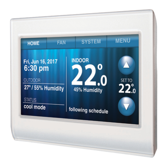
HOME: Touch to display Home screen.
FAN: Select fan mode.
SYSTEM: Select system mode (heat/cool).
MENU: Touch to display options. Start
here to set a program schedule.
CURRENT SCHEDULE: Change temperature
setting and select temporary or permanent hold.
INDOOR CONDITIONS: Shows indoor
temperature and humidity.
CURRENT DATE AND TIME.
CURRENT STATUS: Shows system
mode (heat/cool).
OUTDOOR CONDITIONS: Shows outdoor
temperature and humidity (post registration).
Advertisement
Table of Contents

Related Manuals for Honeywell 9000 Series


Summary of Contents for Honeywell 9000 Series
- Page 1 9000 Series Smart Colour Touchscreen Thermostat Installation Guide HOME: Touch to display Home screen. FAN: Select fan mode. SYSTEM: Select system mode (heat/cool). MENU: Touch to display options. Start here to set a program schedule. CURRENT SCHEDULE: Change temperature setting and select temporary or permanent hold.
-
Page 2: Wallplate Installation
Wallplate Installation 1. Separate wallplate from thermostat. 2. Mount wallplate as shown below. Back of Thermostat Wallplate Drill 3/16" holes for drywall. Drill 7/32" holes for plaster. Mounting screws Wire hole Wall anchors Wallplate CAUTION: ELECTRICAL HAZARD Can cause electric shock or equipment damage. Disconnect power supply before beginning installation. - Page 3 Wiring Terminal holes accept one wire Terminal release Remove jumper loop ONLY if you have both R and RC wires. Terminal Designations Common wire from secondary side of cooling transformer (in case of two transformers) Optional C-wire adapter. Cooling power. Connect to secondary side of cooling system transformer. Heating power.
- Page 4 Wiring Wiring Guide — Conventional Systems Wiring Instructions 1. This thermostat requires a 24VAC common wire to power-up. The K terminal is available for C-wire adapter (THP9045A1098). 2. Straighten the wire. Using a pen’s tip, hold down the terminal and gently slide the wire into the terminal hole.
- Page 5 Wiring Wiring Guide — Heat Pump Systems Wiring Instructions 1. This thermostat requires a 24VAC common wire to power-up. The K terminal is available for C-wire adapter (THP9045A1098). 2. Straighten the wire. Using a pen’s tip, hold down the terminal and gently slide the wire into the terminal hole.
-
Page 6: Initial Setup
Initial Setup Upon initial power up, or after being reset to factory defaults, the initial thermostat options (language, location, and system type) must be set to define the heating/cooling system. Other options can be customised later. Follow prompts on the screen to select appropriate options. Next Next 1. -
Page 7: System Setup
System Setup On the home screen, touch Menu > System Setup to modify the initial system setup. MENU System Setup Next System Setup Options (MENU > System Setup) Screen Title Settings and Options Language English/Français/Español. Thermostat installed in Home/Business (Thermostat is used in a residential (default) or commercial setting). Touch THERMOSTAT button to display the screen where you can enter a custom... -
Page 8: Connecting To The Wi-Fi Network
Connecting to the Wi-Fi Network After the initial setup, walk the homeowner through connecting to a Wi-Fi network. Or, refer the homeowner to the User’s Guide, so that the homeowner can connect the thermostat to the Wi-Fi network later. 1. Connect the Wi-Fi network. Touch to connect the thermostat to the Wi-Fi network. -
Page 9: Setting Advanced Preferences
Setting Advanced Preferences 1. Touch MENU. The thermostat displays a MENU list of options. 2. Select Preferences > Advanced Preferences Preferences. The thermostat displays the first screen of options that you can change. 3. On each screen, make changes as Next needed, then touch to display new... -
Page 10: Troubleshooting
Troubleshooting If you are facing difficulties with your thermostat, please try the following suggestions. Most problems can be corrected easily through these. Display is blank • Check circuit breaker and reset if necessary. • Make sure power switch at heating and cooling system is on. •... -
Page 11: Accessories And Replacement Parts
Accessories & Replacement Parts Please contact your distributor to order replacement parts. Cover plate assembly Part Number THP2400A1027W Specifications Temperature Ranges Electrical Ratings • Heat: 40° to 90°F (4.5° to 32°C) Terminal Voltage Max. Current • Cool: 50° to 99°F (10° to 37°C) (50/60Hz) Rating Operating Ambient Temperature... -
Page 12: Need Help
Apple, iPhone, iPad, IPod touch and iTunes are trademark of Apple Inc. All other trademarks are the property of their respective owners. © 2019 Resideo Technologies, Inc. The Honeywell Home logo is used under license from Honeywell International Inc. All rights reserved.