Fishman Ellipse Matrix Blend, Ellipse VT Installation
- User manual (8 pages) ,
- Manual (4 pages) ,
- Installation manual (2 pages)
Advertisement
Read Me First
Ellipse Matrix Blend and Ellipse VT systems are compatible with many x-braced, round hole guitars with 3.875" to 4.125" diameter soundholes.*
*May not fit Taylor NT guitars, some Larivee guitars or instruments with ladder bracing.
Installing an Ellipse system in a guitar is a simple procedure, but we recommend this job only if you are an experienced guitar repair technician. Please read and understand all these instructions before you install the Ellipse system.
The Ellipse control module is designed to fit in most flat top guitars, but we cannot guarantee it will fit in all instruments. Before you begin installation, remove the strings and pre-fit the control module in the soundhole. Proceed with installation only if the control module lays flat inside the instrument and does not protrude beyond edge of the soundhole.
If you have any questions or comments, please contact us via Service/ Support at www.fishman.com.
Requirements
Saddle Slot
| Minimum saddle slot length: | 2.775" (70.48mm) |
| Maximum E to E string spacing at saddle: | 2.5" (63.5mm) |
Ellipse Module
| Minimum usable soundhole diameter: | 3.875" (98 mm) |
| Maximum usable soundhole diameter: | 4.125" (107 mm) |
| Maximum x-brace height at soundhole: | .312" (7.9 mm) |
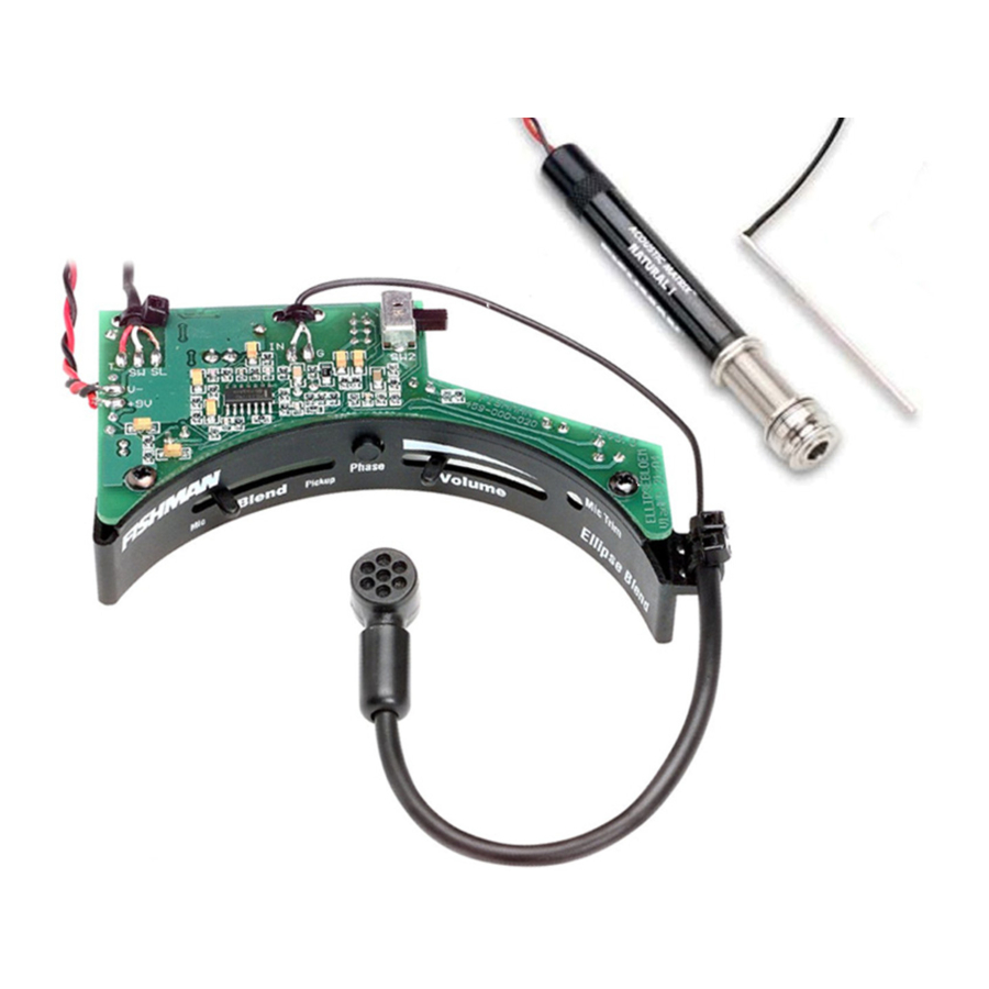
Parts List
- Acoustic Matrix Pickup
- Ellipse control module
- 2 Adhesive backed wire clips
- Battery Clip (with screws)
Tools
- 3/32" (2.3 mm) drill bit
- 1/2" Reamer
- 1/2" Open end wrench
- 3/32" (2.3 mm) Slot head screwdriver
- #1 Phillips screwdriver
- Belt Sander (coarse grit)
- Fine grit sandpaper (#220 & #400 recommended)
- Alcohol wipes or rubbing alcohol and cotton swabs
Pickup Installation
Preliminary
The Acoustic Matrix pickup is handmade with delicate, acoustically transparent materials. Handle the pickup element carefully during installation and please heed these warnings:
- You may damage the pickup if you bend or twist it.
- If you tear or scratch the foil, the pickup will hum when plugged in.
- The pickup should fit easily in the saddle slot, without downward force. If it binds in the sides or touches the ends of the slot, the pickup may hum, produce an unbalanced sound or it may fail.
- Do not trim the pickup or it will hum when it is plugged in. Custom length pickups are available through your Fishman dealer.
Fitting the Pickup
- Remove the strings and the saddle.
- To maintain the current action, remove material from the bottom of the saddle, equal to the height of the pickup (.040" for narrow pickup, .050" for wide pickup). Hold the saddle and the pickup side by side and carefully draw a pencil line across the length of the saddle, at the height of the pickup.
- Use a belt sander to remove saddle material, almost to the pencil line.
- Sand the last bit of saddle material by hand until the bottom is even with the pencil line. The bottom of the saddle must be absolutely flat. Place the saddle on a straight edge and view it in front of a light source. If you can see light, the saddle is not flat.
Note: The heat generated from a belt sander will almost always make a synthetic saddle bow slightly on the bottom. When you sand a bowed saddle by hand, do not hold it in the middle, or the saddle will behave like a spring and you will never get the warp out. Instead, hold the saddle on the ends and lightly sand it in one direction until it is flat. - Hold the pickup upside down in the slot and center it between the span of the strings. Mark the corresponding wire hole location.
![warning]() Note: The distance between the wire hole and adjacent string can be no less than.100" (2.5 mm) for good pickup balance. You can use a 3/32" drill bit to gauge the minimum distance between the string and the pickup wire.
Note: The distance between the wire hole and adjacent string can be no less than.100" (2.5 mm) for good pickup balance. You can use a 3/32" drill bit to gauge the minimum distance between the string and the pickup wire.

- Drill a 3/32" hole for the wire at the marked wire location in the bottom of the saddle slot.
- Clear all debris from the saddle slot. The bottom of the slot must present a clean, flat surface for the pickup.
Note: If the bottom of the slot is uneven, bowed (belly up) or coated with lacquer, it should be re-milled. For detailed instructions, go to the Service/ Support section at www.fishman.com and click on "Product Manuals and Installation Guides", then download "Advanced Undersaddle Pickup Installation." - Thread the wire into the hole and gently insert pickup into the saddle slot. The pickup should fit easily in the saddle slot, without downward force.
- Place the saddle in the slot and check the fit. As a rule of thumb, the saddle should slide easily in and out of the slot, but it will not fall out when overturned. This is called a "sliding fit."
- Saddle Too Tight
If the saddle binds in the slot and is difficult to remove, lightly sand it on one side with fine grit sandpaper until you achieve a sliding fit. - Saddle Too Loose
The saddle is too loose if you can wobble it front to back and it falls out of the slot when overturned. When the saddle is too loose, the pickup signal and/or balance may be degraded. You have two options:- Fit a new saddle (recommended).
- Build up the thickness of the backside of the old saddle:

- Drop the saddle in the slot and draw a line across the back of it (bridge pin side), where the saddle meets the top of the bridge.
- Remove the saddle and get some clear household adhesive tape.
- Apply the tape across the back of the saddle. Position the top edge of the tape halfway between the bottom of the saddle and the pencil line.
- Trim off the excess tape and you are back in business!
- Saddle Too Tight


Endpin Jack Installation
- Remove the endpin and widen the hole with a 1/2" reamer.
- Follow this sequence when you install the endpin jack:

- Large hex nut
- Large washer
- Star washer
- Guitar endblock
- Small dress washer
- Small dress nut
- Strap nut
- Adjust the large hex nut so the smaller threaded portion of the jack protrudes outside the body at least 5/16" (7.9 mm), but not more than 11/32" (8.7 mm).
- Fit the small dress washer and the small dress nut over the end of the jack and then insert a 3/32" (2.3 mm) diameter Allen wrench or screwdriver shaft through the small cross-drilled holes. Tighten the nut with a 1/2" open end wrench while you hold the jack in place with the Allen wrench.
- Thread the strap nut and tighten it.
![]()
Note: The end of the jack should protrude slightly over the strap nut, so when a plug is inserted, it will snap securely in place.


Battery Holder Installation
Mount the battery holder to a small block of hardwood or MDF with the supplied screws. The dimensions for the block are 1.125" x.75" x.5" (28.6 mm x 19 mm x 12.7 mm). Use the battery holder as a template to mark the hole locations on the block. Drill pilot holes for the screws with a 3/32" (2.4 mm) bit. Once you fasten the battery holder to the block, adhere it to the neck block with wood glue or a gap filling cyanoacrylate adhesive such as Loctite® 410.
Control Module Installation
Install the pickup in the bridge and fasten the pickup wire to the terminal block under the metal shield on the control module. The signal wire goes to the "IN" side of the block and the shield wire goes to the "GND" terminal. Screw down the wires with a small flat-head screwdriver.

- Test the area where you will mount the control module. Locate the module flush with the edge of the soundhole, on the bass side. Center the module between the transverse brace above the soundhole and the bass-side x-brace. If you view the soundhole as a clock face (neck at twelve o'clock), position the phase switch at nine o'clock.

- Use 120 grit sandpaper to remove any excess lacquer or buffing compound from the inside edge of the soundhole, then clean this surface with an alcohol wipe or a cotton swab wetted with rubbing alcohol. Let the alcohol dry.
Note: At this point, you may fasten the preamp module in the soundhole and you can expect an adequate and reliable bond. But note that you will achieve the strongest and most effective bond if you now apply a water-based primer/ sealer to the bare wood inside the soundhole. Let the primer/sealer dry before continuing.
Peel back the release film on the bottom of the mount and affix the module to the underside of the soundhole. Apply even, steady pressure to the module to set the adhesive. The adhesive gains maximum hold after 24 hours. - You may separate the control module from the magnetic base for better access inside the guitar. The module is held by two powerful magnets, located on the right and left sides of the unit. To separate the module, locate the tab on the right edge of the unit and push it down, toward the back of the instrument. Once you feel the magnet let go, swing the module towards the soundhole, then separate the left magnet.
- A set of adhesive-backed clips is included to secure the wires inside the instrument. Clean the bare wood surface where you will fasten the clips. Use an alcohol wipe or a cotton swab wetted with rubbing alcohol. Remove the plastic film from the back of each clip to expose the adhesive. Secure the wires and fasten the clips to the side of the guitar.
- Snap a 9 Volt Alkaline battery to the battery clip and fasten it to the battery holder.

 We recommend that you remove the battery prior to shipping or airline travel. If loose inside the guitar, the battery may damage the instrument.
Pickup Voicing Switch (Natural I or II)
String up the guitar and plug it into amplification. Reach into the soundhole with your index finger and locate the slide switch behind the control panel, just to the right of the phase switch. Push this switch away from you for Natural I voicing (bass boosted) and toward you for Natural II voicing (flat). Choose the setting that sounds best with the instrument and the application. Here are some guidelines.
- The Natural I voicing (switch toward bass side) is often used by solo guitarists and singer-songwriters for a full, bass enhanced tone, especially with smaller bodied instruments.
- The Natural II voicing (switch toward treble side) is useful for musicians who play in bands, and who are concerned with controlling boominess at high volume, especially with full-size guitars.
Microphone Positioning (Blend Model)
You can position the microphone to find the "sweet spot" inside the instrument. Experiment with the placement until you find the position that works best in the instrument.
Plug in the guitar and move the Blend slider to the left for mic only. Start with the mic capsule so it faces the back of the guitar. Move the mic closer to the soundhole for more bass. Turn the capsule toward the sides of the instrument for less bass.
")
Mic Trim Control (Blend Model)
Use a small slotted screwdriver to adjust the Mic Trim potentiometer recessed below the volume slider. This is a "set it and forget it" control for calibrating the microphone level in relation to the pickup. Set the Blend slider to the center position and adjust the Mic Trim control until both the microphone and pickup levels are balanced to your liking.
")
Under-Saddle Pickup Installation Tips
Optional Tools
If you install undersaddle pickups regularly, an investment in these specialized tools will quickly pay you back in time saved, with consistent and reliable results.
Sanding Plate (surface plate)
An undersaddle pickup works best when the saddle is absolutely flat on the bottom, and it fits precisely in the slot. It follows that you'll get the best results preparing a saddle when you can work on an absolutely flat sanding surface. Highend woodworking shops and industrial suppliers (ex: Woodcraft or MSC Industrial Supply in North America) carry 9" x 12" granite surface plates that are perfect for the job. As an alternative, we suggest you visit your local home improvement center where you can often find polished marble or granite countertop remnants that make a fine sanding surface. Go for the thickest material available to ensure a stable working surface. You can also use a polished marble cutting board from a retail kitchen supplier. Your sanding plate should be about the size of a sheet of sandpaper.
Sanding Backstop
Use 1/8" (3.2 mm) thick tempered Masonite® hardboard or other suitable material. Cut the backstop to the same length of your sanding plate and 1/2 of its width. True the edges to 90-degrees. As you sand the bottom of the saddle, hold it against the edge of the backstop to maintain a 90-degree angle and ensure complete contact with the pickup once the saddle is installed.
Precision Straight Edge
There is no better way to check the flatness of a saddle than with a quality straight edge. These are available from luthier supplier shops or an industrial supply company.
Reamer (with 15/32" and 1/2" steps)
This specialized tool is available through luthier supply shops. The reamer's 15/32" step gently widens a tapered endpin hole for a perfect fit with our endpin jack.
Jack Insertion Tool
This simple homemade tool makes it really easy to install the jack in the endblock. Get a length of 1/4" (6 mm) wooden dowel stock and cut it to about 17" (43cm). Whittle one end of the dowel to a ball shape, roughly the size of a 1/4" phone plug. When it is time to install the endpin jack, simply insert the dowel into the endblock and capture the jack on the tip of the tool.
Precision Caliper
This tool is indispensable for gauging your progress when you adjust the saddle for the pickup. You can also use it to quickly measure string gauges, and check action with dead-on accuracy. Note that the length of a metal frame caliper makes reliable straight edge.
Mechanical Factors that Affect Pickup Performance
Break Angle
The angle a guitar string forms between the front and back of the saddle is called the string break angle. As string break angle increases, so does pressure on the pickup. And more pressure means better pickup performance. The pressure needed to adequately energize the pickup can be achieved when the break angle is at least 20 degrees.
The saddle height and the relative position of the bridge pins determine the break angle. A new guitar with a tall saddle will usually have sufficient break angle, but an instrument with a low saddle may require an increase. To raise the break angle, the string slots in the bridge can be "ramped"
Sometimes, the saddle seems tall enough, but the bridge-pins are placed in a pattern that lowers the break angle on several strings and throws off the pickup balance. For example: guitars with an asymmetrical "smile" pattern for the bridge pins will often have weak B and high E strings. This can be remedied by ramping the top two strings.
A worst case scenario is when you work on an older guitar with a saddle that barely peeks over the slot and the bridge has been shaved down to lower the action. The unwound strings slide across the saddle with little effort. An instrument in this condition is nearly impossible to achieve a balanced pickup response, due to the low break angle. This instrument requires a neck-reset. A professional neck-reset will restore the saddle height and the string break angle required for good pickup performance.

The 50/50 Rule
The mechanism that drives an undersaddle pickup works like a see-saw. Just as a see-saw has a balance point halfway across its length, a pickup generally works best when the saddle is half in the slot and half above it. Some guitars have very deep slots, and if more than 50% of the saddle lies in the slot, the string-to-string balance of the pickup may be uneven.
If the pickup will not balance and more than 50% of the saddle is buried in the slot, add a hardwood shim under the pickup. To determine the thickness of the shim, subtract 1/2 of the total saddle height from the depth of the slot. Remove an equal amount of material from the bottom of the saddle.
Troubleshooting
| Symptom | Cause | Solution |
WEAK STRING | Saddle is not completely seated. | Push the saddle down over the weak strings. |
| Bottom of saddle is uneven or out of square. | Check bottom of saddle for flatness and squareness. | |
| Debris in the saddle slot. | Remove debris. | |
| Saddle too tight or too loose. | Make sure that the saddle has a sliding fit in the slot. | |
| Soft plastic saddle material. | Use only hard materials such as bone, Corian ® or Tusc | |
| Saddle too deep in slot. | Follow the 50/50 rule, ramp the string slots if necessary. | |
| Uneven or belly up saddle slot. | Sculpt the bottom of the saddle or mill a new slot. | |
| Wire hole too tight. | Widen the wire hole to.094" diameter. | |
| Pickup is binding in the saddle slot. | The saddle slot must be.125" wide for wide format pickup and.094" wide for narrow format pickup. Rout the slot to the correct width. | |
HUM | Saddle is too tight in the slot, poor s/n ratio. | Make sure the saddle has a sliding fit in the slot |
| Torn foil. | Examine the pickup. Replace pickup if the foil is torn. | |
THIN OR WEAK SIGNAL | Weak pressure due to low saddle. | Ramp the string slots. |
INTERMITTENT OR DEAD PICKUP SIGNAL | Pickup is binding in the wire hole (wire hole is too small or misaligned). | Widen the pickup wire hole. |
| Pickup is binding in the saddle slot. | Widen or lengthen the saddle slot to accommodate the pickup. | |
DISTORTION | Weak battery. | Replace the battery. |
Fishman Transducers, Inc.
340 Fordham Road Wilmington, MA 01887
514-000-014 Rev B 3-05
www.fishman.com

Documents / Resources
References
Download manual
Here you can download full pdf version of manual, it may contain additional safety instructions, warranty information, FCC rules, etc.
Download Fishman Ellipse Matrix Blend, Ellipse VT Installation
Advertisement
Thank you! Your question has been received!


Need Assistance?
Do you have a question about the Ellipse Matrix Blend that isn't answered in the manual? Leave your question here.