Table of Contents
Advertisement
Quick Links
Advertisement
Table of Contents

Related Manuals for Pyle PLDTVN65


Summary of Contents for Pyle PLDTVN65
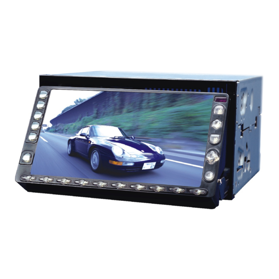
- Page 1 V I D E O V I D E O PLDTVN65...
- Page 4 It is prohibited in law if you watch TV or other multimedia programs while driving. So for your safety, please do not watch programsor operate the instruments. The system is designed to aid you to back cars, we will not take Any responsibility if there is an accident when backing.
-
Page 5: Brief Introduction
Brief Introduction Thank you for purchasing this series of high quality AV products for automobiles. This product is a multi-function system developed by our company and special for high-level cars, business vehicles and special-use vehicles and has a car-carried control center concentrating entertainment, audio-visual, radar distance test, rear view and TV as a whole. -
Page 6: Performance Parameters
Weight Screen size Resolution Dot pitch 2.1.2 Performance parameters Items FM/AM modulation parameters Modulation Display Memory capacity Seeking Band Receive System Seeking Memory method Memory capacity Antenna resistance Voltage Current Audio output Vol. Output tracks Output resistance Frequency response CD Changer Dims CD Changer weight Disc box weight Disc box capacity... - Page 7 Video output Video system Disc Dynamic area Distortion Definition TV system Test voltage Maximum power output Full power output Speaker resistance Bass Tone Treble 2.2 Functions Built-in function: in car DVD, 50W amplifier, DVD, VCD, CD,MP3,CD-R TV: Build in TV function, 40 channels restorable AM/FM receiver: 24 stations restorable Radar measure: radar measuring back sight system (optional) Monitor: introduce 16:9 6.5 inch TFT LCD monitor...
-
Page 8: System Installation
System Installation 3.1 Installation key points The product is specially designed for 12V vehicle, if installed in other vehicles, please install power Changer. To avoid short-circuit, it is strongly suggested to disconnect accumulator cathode before installation. This product should not be used without fuse. Do not connect with the mains directly with that of other electrical equipments. -
Page 9: System Connection Diagram
3.3.1 System connection diagram... - Page 10 , Introduction to buttons 4.1 Buttons on monitor panel RADIO Radio Play CDC Play/Switch Display Data DVD Play/Switch Display Data TV Select AV Select Switch Power/LCD Angle Adjust Last Track/Last Station Next Track/Next Station Reverse/Frequency fine tune(-) Fast forward/Frequency Fine tune(+) BAND Tract Switch/Band Select Title Select/Last Disc...
-
Page 11: Signal Source Selection
4.2 Remote controller button functions LCD Angle adjust(-) Number buttons DVD Language Select Band/Track Switch Manual Memory/DVD Setup OSD Switch Last Track /Last Station/Left (DVD) Last Track Reverse/Frequency fine tune Down Signal Source Select System Setup Volume Adjust(-) 4.2.1 Signal source selection Press the signal source selection key SOURCE on the remote board, the screen will display as the following picture, use entering into the corresponding play mode (AV/CDC/TV/DVD/RADIO) -
Page 12: Volume Control
System operation instruction 5.1 Turn off /start system Press key (>2S) for 1 second to turn off the power of the system, pressing it once again will start the system automatically and restore to the last used status 5.2 Volume control In the volume adjusting mode, press key weaker when press The volume during adjustment will be displayed on the screen (min. - Page 13 5.3.1 LCD Screen Setup Press SET to enter into menu setup, press (18) t o select LCD screen setup, press (18) vertically to confirm into LCD screen setup. The screen will display as the right picture. The setup of brightness, color, contrast, angle and screen view (wide/zoom/center) can be done respectively.
-
Page 14: Time Setting
Or (18) to make setup. Press SET again to exit System Note: When the blue screen is set to screen will display in blue. 5.4 Time setting Press SET to go into System Setup (refer to 5.3.3 in detail), and select TIME ADJ, press entering into time setup mode. -
Page 15: Frequency Switch
Press the digital keys (1~8) on the remote board, directly play the corresponding pre-stored radio channel; Volume adjusting please refer to 5.2; Select other functions(AV,TV,DVD,CDC) to stop playing radio. 6.2 Frequency Switch Press button BAND, you can choose FM(FM1/FM2) and AM. 6.3 Searching station Manual search Press... - Page 16 ,TV operation 7.1 TV play Press TV button to start TV signal receiving. Volume adjust refer to 5.2 Select other function( AV\Radio\DVD\CDC) to stop playing TV. 7.2 Receive preset TV stations Press button to watch TV, press or last TV station. Press number button(0-9) system will switch to that TV station after 3 seconds.
-
Page 17: Dvd Operation
making the TV channel No. you want to store blinking and pressing M once again in 3 seconds, which will store the TV channel into the corresponding Number. This machine can pre-store 40 channels. , DVD operation 8.1 DVD playing Press key DVD, play DVD. -
Page 18: Cdc Operation
8.5 Track switch Under DVD mode, press BAND to change the sound channel. There are 3 selections (L/L, R/R, L/R) for sound channel change; the sound channel status will be displayed on the screen. If it is stereo(L/R) , the display will disappear after 3 seconds. , CDC operation 9.1 CDC playing Press key CDC, play CDC. - Page 19 9.6 CD changer operation 9.6.1 Insert discs Place the box with the side which has CD symbol upward. Draw out plate one by one to stop positions. Place discs on the plates in sequence. Push forward the plates into box until you hear a sound of click. To avoid accidental failure, place only one disc on one plate.
- Page 20 CAUTION: If in any case, the CD changer can not be draw out, press button and push the CD changer inside with strength, then press ejection button , AV operation 10.1 AV play Press AV button, start playing A V select other function(TV Radio DVD CDC),stop playing AV.
- Page 21 , Necessary Disc machine installation , Necessary Disc machine installation In Example of Panasonic DP88 In Example of Panasonic DP88 11.1 Appearance 11.1 Appearance 11.1.1 CD changer 11.1.1 CD changer Door Reset Compact disc area 11.1.2 Compact disc and tray 11.1.2 Compact disc and tray Compact disc inserting direction CAUTION...
-
Page 22: Installation Work
11.2 Installation guidance 11.2 Installation guidance 11.2.1 Installation location 11.2.1 Installation location When the temperature in car is too high, do not install this instrument on rear undercarriage to avoid the problems, in case it is caused by the contact with it. The following locations also should be avoided, Direct sunshine hot air from heater or other high temperature places. -
Page 23: Vertical Installation
Vertical installation Vertical installation Vertical installation as shown below 11.2.4 Typical horizontal installation 11.2.4 Typical horizontal installation Use a hexagonal bolt with 2 washers(M4 8mm) Fix left and right installation trays onto host instrument. Left tray Incline angel <10 degrees (as shown below) <10 degrees Hexagonal bolt with 2... - Page 24 Choose position to install fix trays with double sided adhesive tape. Double sided adhesive tape 2 Tray 2 Cut a small cross on carpet in the position, which is right towards the M5 bolt on tray. Carpet Tray 2 Fix both tray and tape onto installation plate under carpet. -20-...
- Page 25 Use 4 hexagonal bolts(M5) to install the equipment onto the 4 holes on carpet. Carpet 11.2.5 Typical vertical installation Fix trays onto the both sides of equipment by using hexagonal bolt with 2 washers (M4 8mm) Left tray Hexagonal bolt with 2 washers(M4 8mm) 4 Exagonal bolts (M5) 4 Right tray...
- Page 26 11.2.6 The relations between angles and installation holes. 11.2.6 The relations between angles and installation holes. Left tray The above figure has explained clearly the relation between installation holes and installation tray (left and right) angles. There are marks that show the installation angles.
- Page 27 12.1.2 Sensor's installation position 12.1.2 Sensor's installation position According to the quantity installed, the positions can be as follows 30-35cm 30-35cm 30-35cm 30-35cm Remark: The final installation position can be adjusted slightly according to The final installation position can be adjusted slightly according to you car dimensions.
- Page 28 When radar backing car module is connected and you only connect left (right) sensor, monitor will only display left (right) radar signpost, and for right(left) (yellow), there Is only ordinary signpost. When radar is connected, all sensors connected too monitor will display radar signpost as The right picture.
-
Page 29: Precautions When Using The Product
Detection can be affected by: When in a smooth slope, signal can be reflected out. When in the near of a smooth spherical object, signal can be reflected out. When in the near of a sound absorption cotton like object, signal can be absorbed greatly. - Page 30 13.2 Precautions on CD 13.2 Precautions on CD Dirt, dust, scratching and bended disc will result in operation error. Don't place the disc on the object with edge. Don't scratch the disk. Don't bend the disc. The disc should be taken out when it is not in use. The disc should not be placed at the following places The places in straight sun shine.
-
Page 31: Problem No Sound
Problem Problem No sound No sound No image No image Operation is Operation is failure. failure. The sound skips The sound skips The sound skips The sound skips from vibration from vibration Packing list Packing list DVD Host equipment CD changer Remote controller Power audio output wire Connecting wire from the...