Table of Contents
Advertisement
Quick Links
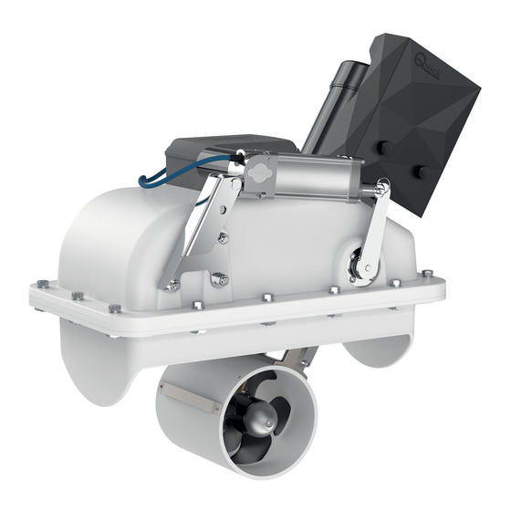
BTR Series
RETRACTABLE THRUSTERS
BTR 140 30 - 140 40
BTR 185 65 - 185 85 - 185 105
BTR 250 120 - 250 140 - 250 240
BTR 300 250 - 300 270 - 300 300
*EN - INSTALLATION AND USER'S MANUAL
REV 001C
January, 2023
*Other languages available by scanning the QR code on the
back of this manual or on the label on the product.
*Altre lingue disponibili scansionando il codice QR presente
IT
sul retro del seguente manuale o sull'etichetta alloggiata sul
prodotto.
*Otros idiomas disponibles escaneando el código QR en la
ES
parte posterior de este manual o en la etiqueta del producto.
*Autres langues disponibles en scannant le code QR au dos
FR
de ce manuel ou sur l'étiquette du produit.
*Andere Sprachen sind durch Scannen des QR-Codes auf der
DE
Rückseite dieser Betriebsanleitung oder auf dem Aufkleber
am Produkt verfügbar.
*Outros idiomas disponíveis, digitalizando o código QR no
PT
verso deste manual ou no rótulo do produto.
Advertisement
Table of Contents

Related Manuals for Quick BTR Series


Summary of Contents for Quick BTR Series
- Page 1 BTR Series REV 001C January, 2023 RETRACTABLE THRUSTERS BTR 140 30 - 140 40 BTR 185 65 - 185 85 - 185 105 BTR 250 120 - 250 140 - 250 240 BTR 300 250 - 300 270 - 300 300...
- Page 3 11 - Product disposal 12 - List of components 12.0 - BTR 140 12.1 - BTR 185 12.2 - BTR 250 12.3 - BTR 300 13 - Spare parts 14 - Dimensions QUICK BTR SERIES INSTALLATION AND USER’S MANUAL - REV 001C...
-
Page 5: Information About The Product
1 - Information about the product BTR Series READ THIS INSTRUCTION MANUAL CAREFULLY BEFORE USING THE PRODUCT. IF IN DOUBT, CONTACT YOUR QUICK DEALER. ® QUICK ® RESERVES THE RIGHT TO MODIFY THE TECHNICAL CHARACTERISTICS OF THE EQUIPMENT AND THE CONTENTS OF THIS MANUAL WITHOUT PRIOR NOTICE. -
Page 6: Important Notes
• TFH Fuse holder BTR Series 3 - Introduction BEFORE USING THE PRODUCT, PLEASE READ THIS USER’S MANUAL CAREFULLY. IF IN DOUBT, PLEASE CONSULT YOUR QUICK® DEALER. 3.0 - Important notes This manual features Warning and/or Caution symbols that are important for safety. -
Page 7: Installation Requirements
The Quick® retractable thruster is sold separately from the counter flange which can be supplied in different materials based on the different type of hulls. Quick® can provide stainless steel, aluminium alloy or GRP supports, which are essential for a fast, sturdy and precise installation. - Page 8 • To avoid damage, position the retractable thruster so that the hatch is not affected by the thruster driving cone of the boat (examples 1 and 2), in both directions of travel. BARYCENTRE • The longer the lengths L1 and L2, the greater the thrust generated around the barycentre. QUICK BTR Series INSTALLATION AND USER’S MANUAL - REV 001C...
-
Page 9: Installation
CUT LINE COUNTER FLANGE HULL • Shape the central parts of the 4 indicated sides of the counter flange by adapting them to the curve of the hull (fig. 1C). QUICK BTR Series INSTALLATION AND USER’S MANUAL - REV 001C... - Page 10 350mm 480mm 604mm 100mm 95mm 150mm 110mm 200mm 280mm 310mm 440mm 20mm Fig.4 • Make the hull opening by cutting along the line of the marked cutting area (fig. 4). QUICK BTR Series INSTALLATION AND USER’S MANUAL - REV 001C...
- Page 11 WARNING: take special care to avoid interference between the cover and the hull opening. Too precise contacts will cause damage to the entire movement system (fig.7). Fig.7 Fig.8 HINGE SIDE COUNTER FLANGE 45° HATCH 5 mm QUICK BTR Series INSTALLATION AND USER’S MANUAL - REV 001C...
- Page 12 • Fix the hinge and the hatch bracket in the positions made using stainless steel screws suitable for the application. • Adjust the central hinge screw (fig. 11) and position it correctly so that the hatch opens unhindered. QUICK BTR Series INSTALLATION AND USER’S MANUAL - REV 001C...
- Page 13 15. WARNING: after about a week from installation, check the correct tightening of the screws to compensate for any settling of the O-ring. QUICK BTR Series INSTALLATION AND USER’S MANUAL - REV 001C...
-
Page 14: Motor Installation
• Hook the ends of the cable to the two springs (already • Final installation of the cable in the hatch (ref. D). positioned on the tilting body) (ref. C). QUICK BTR Series INSTALLATION AND USER’S MANUAL - REV 001C... -
Page 15: Adjustment Procedure
If the stroke is not enough to reach the limit switch, adjust the latter during closing (point 4.8). The retractable thruster is factory-set, so it should not be necessary to adjust it during closing. CONSTANT VELOCITY JOINT QUICK BTR Series INSTALLATION AND USER’S MANUAL - REV 001C... -
Page 16: Actuator Adjustment
• Power the retractable thruster (fig. 22) which will automatically close. END-OF-STROKE CABLE STOP CABLE • To ensure correct operation, open the hatch a few times via the control (fig. 23). SPRING QUICK BTR Series INSTALLATION AND USER’S MANUAL - REV 001C... -
Page 17: Wiring Diagram
* COMMON NEGATIVE FOR BATTERY GROUPS. ** WARNING: IN CASE OF OVERTEMPERATURE, THE THERMAL CUT-OUT ON THE MOTOR WILL TRIGGER AND INTERRUPT THE NEGATIVE CONTACT ON THE CONTACTOR. WAIT FOR THE TIME NEEDED FOR REACTIVATION. QUICK BTR Series INSTALLATION AND USER’S MANUAL - REV 001C... - Page 18 To the left contactor Black To the right contactor Yellow Green Contact 2 QAJ female connector White Contact 1 QAJ female connector Power Supply Negative Power Supply Positive Linear actuator QUICK BTR Series INSTALLATION AND USER’S MANUAL - REV 001C...
-
Page 19: Operation
If the maximum current/load limit is too low compared to the real needs of use, the thermal cut-outs of the actuator may be tripped during retractable thruster closing and opening with error 1 and 7 flashing. QUICK BTR Series INSTALLATION AND USER’S MANUAL - REV 001C... -
Page 20: Light Signals
The problem is reported if the board detects an interruption in the motor control power line. Check the wiring of the power lines from the board to the reversing contactor/motor unit installed on the retractable thruster. QUICK BTR Series INSTALLATION AND USER’S MANUAL - REV 001C... -
Page 21: Important Warnings
Error detection from the TCD If the TCD sends an error signal into the network (extended command, line interruption, short circuit on the right or left output), the retractable thruster performs the rising procedure. QUICK BTR Series INSTALLATION AND USER’S MANUAL - REV 001C... -
Page 22: Maintenance
Separate the products for disposal in accordance with the regulations in force in your area or return the product to the seller when purchasing a new equivalent product. Local regulations may impose severe penalties for the improper disposal of this product. QUICK BTR Series INSTALLATION AND USER’S MANUAL - REV 001C... -
Page 23: List Of Components
50 O-RING 71 NUT 89 CABLE 14 PIN 33 BEARING 51 BEARING 72 SCREW 15 ACTUATOR LEVER 34 EXTERNAL SNAP RING 53 EXTERNAL SNAP RING 73 ROPE GUIDE 16 PIN QUICK BTR Series INSTALLATION AND USER’S MANUAL - REV 001C... - Page 24 BTR Series 12 - List of components 12.0 - BTR 140 QUICK BTR Series INSTALLATION AND USER’S MANUAL - REV 001C...
- Page 25 BTR Series 12 - List of components 12.1 - BTR 185 86 85 QUICK BTR Series INSTALLATION AND USER’S MANUAL - REV 001C...
- Page 26 BTR Series 12 - List of components 12.2 - BTR 250 19 18 19 23 QUICK BTR Series INSTALLATION AND USER’S MANUAL - REV 001C...
- Page 27 BTR Series 12 - List of components 12.3 - BTR 300 18 17 QUICK BTR Series INSTALLATION AND USER’S MANUAL - REV 001C...
- Page 28 18A OSP HINGE VERT. FIX. ANGLE BRACKET BTR140 FVSLPVNG1400A00 18B OSP HINGE VERT. FIX. ANGLE BRACKET BTR185 FVSLPVNG1850A00 18C OSP HINGE VERT. FIX. ANGLE BRACKET BTR250 FVSLPVNG2500A00 18D OSP HINGE VERT. FIX. ANGLE BRACKET BTR300 FVSLPVNG3000A00 QUICK BTR Series INSTALLATION AND USER’S MANUAL - REV 001C...
- Page 29 BTR Series 14 - Dimensions BTR 140 575 (22 41 /64 500 (19 11 /16 QUICK BTR Series INSTALLATION AND USER’S MANUAL - REV 001C...
- Page 30 BTR Series 14 - Dimensions generic image QUICK BTR Series INSTALLATION AND USER’S MANUAL - REV 001C...
- Page 31 997 (39" 1/4) 462 (18" 3/16) 514 (20" 1/4) 553 (21" 3/4) 570 (22" 7/16) 859 (33" 13/16) 475 (18" 11/16) 200 (7" 7/8) 149 (5" 7/8) 114 (4" 1/2) QUICK BTR Series INSTALLATION AND USER’S MANUAL - REV 001C...
- Page 32 January, 2023 BTR 18585 - 185105 BTR 250150 - 250220 BTR 300240 - 300300 - 300400 Product serial number QUICK S.p.A. - Via Piangipane, 120/A - 48124 Piangipane (RAVENNA) - ITALY ® Tel. +39.0544.415061 - Fax +39.0544.415047 - www.quickitaly.com - quick@quickitaly.com...