Table of Contents
Advertisement
Quick Links
VFI Series Vent Free Gas Fireplace
Installation & Operating Instructions
Models:
VFI33L(N/P)(V/I), VFI33C(N/P)(V/I)
WARNING: If the information in this
manual is not followed exactly, a fire or
explosion may result causing property
damage, personal injury or loss of life.
•
Do not store or use gasoline or other
flammable vapors and liquids in the
vicinity of this or any other appliance.
•
WHAT TO DO IF YOU SMELL GAS
– Do not try to light any appliance.
– Do not touch any electrical switch; do
not use any phone in your building.
– Leave the building immediately.
– Immediately call your gas supplier from
a neighbor's phone. Follow the gas
supplier's instructions.
– If you cannot reach your gas supplier,
call the fire department.
•
Installation and service must be performed
by a qualified installer, service agency or
the gas supplier.
Monessen • VFI33 Owner Manual • 20307670 • Rev H • 1/2020
This is an unvented gas-fired heater. It uses air
(oxygen) from the room in which it is installed.
Provisions for adequate combustion and venti-
lation air must be provided. Refer to Page 7.
INSTALLER: Leave this manual with the appliance.
CONSUMER: Retain this manual for future
reference.
Advertisement
Table of Contents

Related Manuals for Monessen Hearth VFI Series


Summary of Contents for Monessen Hearth VFI Series
- Page 1 VFI Series Vent Free Gas Fireplace Installation & Operating Instructions Models: VFI33L(N/P)(V/I), VFI33C(N/P)(V/I) WARNING: If the information in this manual is not followed exactly, a fire or explosion may result causing property damage, personal injury or loss of life. •...
-
Page 2: Table Of Contents
VFI33 Vent Free Gas Fireplace System CONTENTS Thank you and congratulations on your purchase of a Monessen vent free gas fireplace. PLEASE READ THE INSTALLATION AND OPERATION INSTRUCTIONS BEFORE USING THE APPLIANCE. IMPORTANT: Read all instructions and warnings carefully before starting installation. Failure to follow these instructions may result in a possible fire hazard and will void the warranty. -
Page 3: Important Safety Information
VFI33 Vent Free Gas Fireplace System IMPORTANT SAFETY INFORMATION OWNER INSTALLER Please retain these instructions for future reference. Please leave these instructions with the appliance. WARNING! • Any change to this heater or its controls can be dangerous. • Improper installation or use of the heater can cause serious injury or death from fire, burns, explosion or carbon monoxide poisoning. -
Page 4: Codes
VFI33 Vent Free Gas Fireplace System IMPORTANT SAFETY INFORMATION 20. During manufacturing, fabricating and shipping, various THIS APPLIANCE MAY BE INSTALLED IN AN components of this appliance are treated with certain AFTER-MARKET, PERMANENTLY LOCATED, oils, films or bonding agents. These chemicals are not MANUFACTURED (MOBILE) HOME, WHERE harmful but may produce annoying smoke and smells NOT PROHIBITED BY LOCAL CODES. -
Page 5: Product Features
VFI33 Vent Free Gas Fireplace System PRODUCT FEATURES GAS SPECIFICATIONS AND ORIFICE SIZE VFI33 CONTROLS MAX. INPUT MIN. INPUT ORIFICE MODEL FUEL CONTROL (BTU/h) (BTU/h) SIZE Surround VFI33LNV NAT. Millivolt 28,000 19,000 VFI33LPV Millivolt 27,000 22,000 VFI33CNV NAT. Millivolt 28,000 19,000 VFI33CPV Millivolt... -
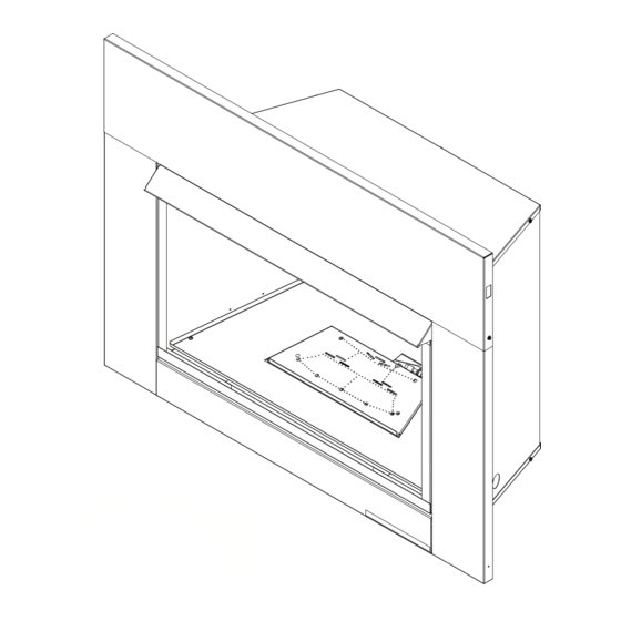
Page 6: Fireplace And Framing Dimensions
VFI33 Vent Free Gas Fireplace System FIREPLACE AND FRAMING DIMENSIONS Cold Climate Switch Master Switch Figure 2. Cold Climate Option mode (as it comes from the factory), your pilot remains To remedy this issue, your fireplace has been designed with unlit until needed, saving you fuel. -
Page 7: Pre-Installation Information
VFI33 Vent Free Gas Fireplace System PRE-INSTALLATION INFORMATION FRAMING DIMENSIONS style designed to be operated with optional devices for ON/OFF functions. The following options may be used If unit is to be “built in,” fireplace framing can be built before with the millivolt controlled heater. -
Page 8: Clearances And Height Requirements
VFI33 Vent Free Gas Fireplace System CLEARANCE AND HEIGHT REQUIREMENTS WARNING! The dimensions shown in Figures 4 and 5 3 / 4 and defined in the fireplace manufacturer's instructions are minimum clearances to maintain when installing this heater. Left and right clearances are determined when facing the front of the heater. -
Page 9: Before Installing The Fireplace Insert
VFI33 Vent Free Gas Fireplace System CLEARANCE AND HEIGHT REQUIREMENTS BEFORE INSTALLING THE FIREPLACE INSERT 12" Have fireplace floor and chimney professionally cleaned to remove ashes, soot, creosote or other obstructions. Close and seal any fresh air vents or ash clean-out doors located 10"... -
Page 10: Installation
VFI33 Vent Free Gas Fireplace System INSTALLATION INSTALL CANOPY The gas log heater must be installed at least 5" above any combustible flooring material, such as carpeting or 1. Remove the fireplace screen as described in the previ- tile, which is closer than 14" to the base of the fireplace. ous section. -
Page 11: Secure Heater To Floor
VFI33 Vent Free Gas Fireplace System INSTALLATION SECURE HEATER TO FLOOR 2. Lift grate and base assembly out of the firebox. NOTE: Clearance requirements as detailed in “Clearances 3. Secure the firebox with two anchoring screws ( ⁄ " x 1 ⁄... -
Page 12: Connect Gas Line
VFI33 Vent Free Gas Fireplace System CONNECT GAS LINE CONNECTING THE GAS LINE WARNING! Connecting directly to an unregulated propane/ NOTICE: A qualified gas appliance installer must connect LPG tank can cause an explosion the heater to the gas supply. Consult all local codes. To reach factory installed flex line, go through access door WARNING! on right or left side of firebox. -
Page 13: Gas Pressure - Millivolt
VFI33 Vent Free Gas Fireplace System GAS PRESSURE — MILLIVOLT CHECKING GAS PRESSURE: – MILLIVOLT CONTROL Figure 18. The valve regulator controls the burner pressure which should be checked at the pressure test point. Turn captured screw counter clockwise two or three turns and then place tubing to pressure gauge over test point (Use test point “OUT”... -
Page 14: Electrical Wiring - Millivolt
VFI33 Vent Free Gas Fireplace System ELECTRICAL WIRING — MILLIVOLT ODS Pilot On/Off Switch Field Installed Optional Pilot Wall Switch or Remote Receiver Valve On/Off Switch Spade Terminal TH = 3 TP = 1 TP/TH = 2 Switch Figure 19. Wiring Diagram FP2112a wiring diagram 8/09... -
Page 15: Connect Remote Receiver
VFI33 Vent Free Gas Fireplace System ELECTRICAL WIRING — MILLIVOLT CONNECT REMOTE RECEIVER THESE INSTRUCTIONS SUPERCEDE THE SECTION ENTITLED “HEARTH MOUNT” IN THE MILLIVOLT HAND-HELD REMOTE INSTRUCTIONS SUPPLIED WITH THE REMOTE. Figure 20. 1. Remove bottom control door. 2. Connect the remote connector wires located in the unit to the remote receiver. -
Page 16: Operating Instructions - Millivolt
VFI33 Vent Free Gas Fireplace System OPERATING INSTRUCTIONS – MILLIVOLT FOR YOUR SAFETY READ BEFORE LIGHTING WARNING! If you do not follow these instruction exactly, a fire or explosion may result causing property damage, personal injury or loss of life. A. -
Page 17: Lighting Pilot
VFI33 Vent Free Gas Fireplace System OPERATING INSTRUCTIONS — MILLIVOLT LIGHTING PILOT FOR THE FIRST TIME APPROVED LEAK TESTING METHOD You may check for gas leaks with the following methods only: • Soap and water solution • An approved leak testing spray •... -
Page 18: Lighting Burner
VFI33 Vent Free Gas Fireplace System OPERATING INSTRUCTIONS – MILLIVOLT LIGHTING BURNER LIGHTING THE BURNER Depress and turn the knob counterclockwise to the “ON” position. It will take less than four (4) seconds for the burner to ignite. MAIN BURNER SWITCH This switch allows you to turn on and to turn off the main burner without using the gas valve knob. -
Page 19: Check Gas Pressure - Ipi
VFI33 Vent Free Gas Fireplace System ELECTRICAL INSTALLATION — IPI CHECK GAS PRESSURE – IPI WARNING! 1. Check gas type. The gas supply must be the same as Electrical connections should only be stated on the appliance’s rating decal. If the gas supply performed by a qualified, licensed electrician. -
Page 20: Ipi System Wiring Diagram
VFI33 Vent Free Gas Fireplace System ELECTRICAL INSTALLATION – IPI WALL SWITCH INSTALLATION board. Run wire to desired location on wall. Up to 50 feet of 18 gauge wire may be used if necessary. Attach wires The wall switch wire connection is located off the wire to wall switch. -
Page 21: Operating Instruction - Ipi
VFI33 Vent Free Gas Fireplace System OPERATING INSTRUCTIONS – IPI FOR YOUR SAFETY READ BEFORE LIGHTING WARNING! If you do not follow these instructions exactly, a fire or explosion may result causing property damage, personal injury or loss of lie. A. -
Page 22: Operating And Indications
VFI33 Vent Free Gas Fireplace System OPERATING INSTRUCTIONS – IPI OPERATIONS AND INDICATIONS Cold RF Learn Climate Button Switch Master Switch ECOLOGIC CON- TROL System Set Up Chart NOTE: When using ON/OFF wall switch, the master switch, located in bottom of fireplace must be in the ON position to perform all configuration setup operations. -
Page 23: Electrical Wiring - Fan
VFI33 Vent Free Gas Fireplace System ELECTRICAL WIRING – FAN WARNING! WARNING! This fireplace has a three-prong, grounded Never attempt to service heater while it is electrical plug. This plug helps protect you plugged in, operating, or hot. Burns and/or against electrical shock. -
Page 24: Log Placement
VFI33 Vent Free Gas Fireplace System LOG PLACEMENT CAST IRON GRATE INSTALLATION WARNING! Install the cast iron grate by inserting screw head on back of right side of grate into the “I” shaped slot on front right The positioning of the logs is critical to the safe corner of unit. -
Page 25: Rock Wool Placement
VFI33 Vent Free Gas Fireplace System LOG PLACEMENT ROCK WOOL PLACEMENT 2. Place front right log (#2) on right pin located on burner and right grate bar. Figure 28. Slide log #1 forward so Before installing logs, place rock wool in dime size pieces that it is tight against log #2. - Page 26 VFI33 Vent Free Gas Fireplace System LOG PLACEMENT left grate bar. Rest top right portion of log on right front Right Top Left Top log. Figure 31. Log #8 Log #7 Left Front Log #5 Figure 33. Place Right Top Log #8 LG636 NB 18 24 log 8 Figure 31.
-
Page 27: Install Highland Oak Logs
VFI33 Vent Free Gas Fireplace System LOG PLACEMENT HIGHLAND OAK LOGS Right Rear Log #3 INSTALL 18", (F,R) HIGHLAND OAK LOGS ON NATU- RAL BLAZE BURNER 1. Place the #1 log (the “chunk”) on the grate bar right side of the burner adjacent to the controls. Figure 34. Ember Chunk Log #1 Figure 36. -
Page 28: Install Kentucky Wildwood Logs
VFI33 Vent Free Gas Fireplace System LOG PLACEMENT locating blocks on logs #4 and #5. Figure 39. PLACE THE DECORATIVE ROCK 7. Place right top log (#7) on right rear log (#3) and right Optional volcanic rock may be placed around the unit on front log (#2) using locators on the bottom of log #7 and the floor of the firebox. - Page 29 VFI33 Vent Free Gas Fireplace System LOG PLACEMENT 6. Place center top log #6 on two (2) pins on top of log #2. The front end of log #6 should rest on log #4. Log #6 Log #3 Figure 46. Figure 43.
-
Page 30: Install Beachcomber And Riverwood Logs
VFI33 Vent Free Gas Fireplace System BEACHCOMBER AND RIVERWOOD LOGS 4. Place the right log (#4) on the bar located on the right INSTALL 18" BEACHCOMBER AND RIVERWOOD side of the burner. (See Figure 51) LOGS ON NATURAL BLAZE BURNER 1. -
Page 31: Fireglass Placement
VFI33 Vent Free Gas Fireplace System FIREGLASS PLACEMENT NOTE: Two (2) bags of glass are supplied with the fireplace. Both bags may be used to cover the entire floor and burner. We advise against using additional glass as too much can cut off the proper amount of air the burner needs to operate cleanly. -
Page 32: Flame Appearance
VFI33 Vent Free Gas Fireplace System FLAME APPEARANCE VISUAL FLAME CHECK Thermocouple Flames from the pilot, front and rear burner should be for Natural visually checked as soon as the heater is installed. In addition, periodically check the flames visually during operation. -
Page 33: Operating Instructions
VFI33 Vent Free Gas Fireplace System OPERATING INSTRUCTIONS FOR YOUR SAFETY READ BEFORE LIGHTING WARNING! If you do not follow these instruction exactly, a fire or explosion may result causing property damage, personal injury or loss of life. A. This appliance is equipped with a piezo ignition device which automatically lights the pilot. If the piezo is not working properly see Match Lighting Instructions on Page 33. -
Page 34: Millivolt/Thermostat Control Lighting Instructions
VFI33 Vent Free Gas Fireplace System OPERATING INSTRUCTIONS MILLIVOLT/THERMOSTAT CONTROL LIGHTING INSTRUCTIONS 1. STOP! Read the safety information label. 2. Make sure the manual shutoff valve is fully open. 3. This gas log set is equipped with an ignition device (piezo) which automatically lights the pilot. If piezo ignitor does not light the pilot, refer to instructions for “Match Lighting Instructions,”... -
Page 35: Blower Operation
VFI33 Vent Free Gas Fireplace System OPERATING INSTRUCTIONS MATCH LIGHTING INSTRUCTIONS 1. Remove any items necessary for easy access to the pilot (for example: logs, screens, etc.). 2. Follow appropriate lighting instructions found previously. Instead of pushing and releasing the piezo button, light a match and hold the flame to the end of the pilot and ignite the pilot. -
Page 36: Cleaning And Servicing
VFI33 Vent Free Gas Fireplace System CLEANING AND SERVICING WARNING! Turn off heater and allow to cool before cleaning. Disconnect electrical power before cleaning or servicing. PERIODIC CLEANING ANNUAL CLEANING AND INSPECTION Refer to parts diagram for location of items discussed Refer to parts diagram for location of items discussed below. -
Page 37: Troubleshooting
VFI33 Vent Free Gas Fireplace System TROUBLESHOOTING WARNING! Turn appliance OFF and allow to cool before servicing. Only a qualified service person should service and repair the heater. NOTE: All troubleshooting items are listed in order of operation. OBSERVED PROBLEM POSSIBLE CAUSE SOLUTION When ignitor button is pressed,... - Page 38 VFI33 Vent Free Gas Fireplace System TROUBLESHOOTING OBSERVED PROBLEM POSSIBLE CAUSE SOLUTION ODS/pilot lights, but flame 1. Control knob not fully pressed in. 1. Press in control knob fully. goes out when control knob is 2. Control knob not pressed in long 2.
-
Page 39: Replacement Parts
VFI33 Vent Free Gas Fireplace System REPLACEMENT PARTS FIREBOX ASSEMBLY REFERENCE NO. DESCRIPTION QTY. REPLACEMENT PART NO. Screen Assembly 20306285K Canopy Assembly 20307546K Lower Control Panel 20306484K Left Firebrick 20307263K (Cinn) 20307771K (Col. Red) Center Firebrick 20307264K (Cinn) 20307769K (Col. Red) Right Firebrick 20307262K (Cinn) 20307770K (Col. -
Page 40: Millivolt Burner Assembly
VFI33 Vent Free Gas Fireplace System REPLACEMENT PARTS MILLIVOLT BURNER ASSEMBLY CONTEMPORARY TRADITIONAL BURNER BURNER DESCRIPTION VFI33CNV VFI33CPV VFI33LNV VFI33LPV On/Off Switch SRV32D0232 SRV32D0232 SRV32D0232 SRV32D0232 Piezo Ignitor SRV14D0503 SRV14D0503 SRV14D0503 SRV14D0503 ODS Pilot Assembly SRV14D0473 SRV14D0477 SRV14D0473 SRV14D0477 Piezo Wire SRV00K0632 SRV00K0632 SRV00K0632... -
Page 41: Ipi Burner Assembly
VFI33 Vent Free Gas Fireplace System REPLACEMENT PARTS IPI BURNER ASSEMBLY CONTEMPORARY TRADITIONAL BURNER BURNER DESCRIPTION VFI33CNI VFI33CPI VFI33LNI VFI33LPI Cold Climate Switch SRV95E0111 SRV95E0111 SRV95E0111 9SRV5E0111 On/Off Switch SRV32D0232 SRV32D0232 SRV32D0232 SRV32D0232 Gas Valve SRV95E0101 SRV95E0102 SRV95E0101 SRV95E0102 Control Box SRV95E0100 SRV95E0100 SRV95E0100... -
Page 42: Berkley Oak Logs
VFI33 Vent Free Gas Fireplace System REPLACEMENT PARTS (BENEATH #8) BERKLEY OAK LOGS 810107 NB18 24 log parts REF. DESCRIPTION QUANTITY BO18-R BO18-F Ember Chunk 81D0110K 81D0109K Right Front Log 81D0059K 81D0083K Right Rear Log 81D0060K 81D0084K Left Rear Log 81D0061K 81D0085K Left Front Log... -
Page 43: Beachcomber And Riverwood Logs
VFI33 Vent Free Gas Fireplace System BEACHCOMBER AND RIVERWOOD LOGS Ref Description Qty BC18-R BC24-R BC30-R RW18-R RW24-R RW30-R Rear log, #1 20308895 20308748 20308917 20308931 20308754 20308901 Front left log, #2 20308897 20308750 20308750 20308933 20308756 20308756 Front center log, #3 20308896 20308749 20308918... -
Page 44: Highland Oak Logs
VFI33 Vent Free Gas Fireplace System REPLACEMENT PARTS (BENEATH #7) HIGHLAND OAK LOGS REF. DESCRIPTION QUANTITY HO18-R HO18-F Ember Chunk 81D0110K 81D0109K Right Front Log 81D0011K 81D0035K Right Rear Log 81D0012K 81D0036K Left Rear Log 81D0013K 81D0037K Left Front Log 81D0014K 81D0038K Left Top Log... -
Page 45: Kentucky Wildwood Logs
VFI33 Vent Free Gas Fireplace System REPLACEMENT PARTS KENTUCKY WILDWOOD LOGS REF DESCRIPTION QUANTITY KW18-R Bottom front right log, #1 20305902 810107 Bottom rear right log, #2 20305903 KW24 logs Bottom rear left log, #3 20305904 Bottom front left log, #4 20305905 Center left log, #5 20305906... -
Page 46: Warranty
VFI33 Vent Free Gas Fireplace System Hearth & Home Technologies ► LIMITED LIFETIME WARRANTY Hearth & Home Technologies, on behalf of its hearth brands (“HHT”), extends the following warranty for HHT gas, wood, pellet and electric hearth appliances that are purchased from an HHT authorized dealer. WARRANTY COVERAGE: HHT warrants to the original owner of the HHT appliance at the site of installa on, and to any transferee taking ownership of the appliance at the site of installa on within two years following the date of original purchase, that the HHT appliance will be free from... - Page 47 VFI33 Vent Free Gas Fireplace System WARRANTY CONDITIONS: • This warranty only covers HHT appliances that are purchased through an HHT authorized dealer or distributor. A list of HHT authorized dealers is available on the HHT branded websites. • This warranty is only valid while the HHT appliance remains at the site of original installa� on. •...
- Page 48 Monessen, a brand of Hearth & Home Technologies 7571 215th Street West, Lakeville, MN 50044 www.monessenhearth.com...