Monessen Hearth VWF30 Installation And Operating Instructions Manual
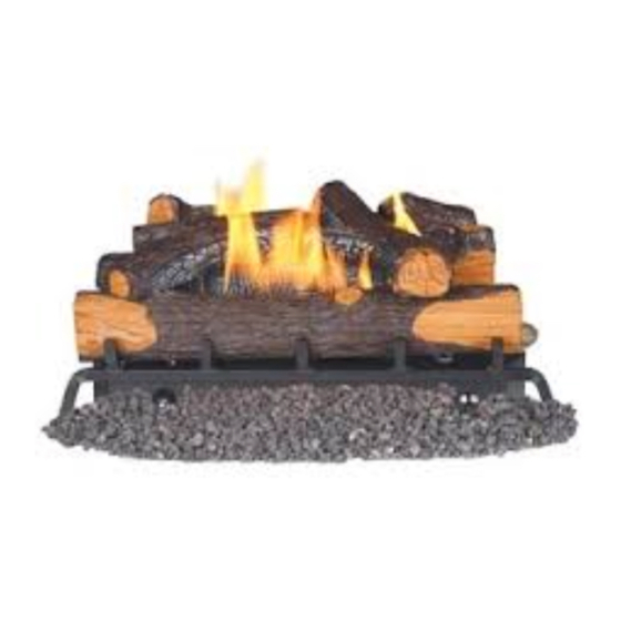
Vented gas log set
Hide thumbs
Also See for VWF30:
- Brochure & specs (4 pages) ,
- Installation and operating instructions manual (54 pages) ,
- Installation and operating instructions manual (32 pages)
Table of Contents
Advertisement
VENTED GAS LOG SET
INSTALLATION AND OPERATING
INSTRUCTIONS
MODELS: VWF18 VWF24 VWF30 VWF36
Natural Gas or Propane/LPG Control Type:
Manual and Milli-Volt
Approved to ANSI Z21.60
This gas log set is to be installed only
in a solid-fuel burning fi replace with a
working fl ue constructed of noncombus-
tible material.
MHS, Inc.
READ AND SAVE THESE INSTRUCTIONS
WARNINGS
IF THE INFORMATION IN THIS MANUAL IS NOT
FOLLOWED EXACTLY, A FIRE OR EXPLOSION MAY
RESULT CAUSING PROPERTY DAMAGE, PERSONAL
INJURY OR LOSS OF LIFE.
–
Do not store or use gasoline or other fl ammable
vapors and liquids in the vicinity of this or any other
appliance.
–
WHAT TO DO IF YOU SMELL GAS
• Do not try to light any appliance.
• Do not touch any electrical switch; do not use any
phone in your building.
• Immediately call your gas supplier from a neighbor's
phone. Follow the gas supplier's instructions.
• If you cannot reach your gas supplier, call the fi re
department.
–
Installation and service must be performed by
a qualified installer, service agency or the gas
supplier.
Advertisement
Table of Contents

Related Manuals for Monessen Hearth VWF30


Summary of Contents for Monessen Hearth VWF30
- Page 1 MHS, Inc. VENTED GAS LOG SET INSTALLATION AND OPERATING INSTRUCTIONS MODELS: VWF18 VWF24 VWF30 VWF36 Natural Gas or Propane/LPG Control Type: Manual and Milli-Volt Approved to ANSI Z21.60 This gas log set is to be installed only in a solid-fuel burning fi replace with a working fl...
-
Page 2: Table Of Contents
VWF30 American Oak Log Placement...21 VWF24B Log Placement ...23 VWF24/18 Split River Oak Log Placement ..24 VWF30/24 Split River Oak Log Placement ..26 VWF36/30 Split River Oak Log Placement ..28 VWF18 Split Pine Placement ...30 VWF24 Split Pine Placement ...32 VWF30 Split Pine Placement ...32... -
Page 3: Important Safety Information
INSTALLER Please leave these instructions with the appliance. Read these instructions carefully before installing or trying to operate this gas log set. • Any change to this appliance or its controls can be dangerous. • Improper installation or use of the heater can cause serious injury or death from fi re, burns, explosion or carbon monoxide poisoning. -
Page 4: Product Specifi Cations
National Fireplace Institute (NFI) as Gas Specialists. www.nfi certifi ed.org PRODUCT SPECIFICATIONS MINIMUM HEARTH DIMENSIONS MANUAL CONTROL Model VWF18 21" 13 VWF24 27" 13 VWF30 33" 13 VWF36 39" 13 MILLI-VOLT CONTROL* Model VWF18 25" 13 VWF24 31" 13 VWF30 37"... -
Page 5: Getting Started
MAKE SURE YOU HAVE RECEIVED ALL PARTS: Check your packing list to verify that all listed parts have been received. You should have the following: BURNER - GRATE ASSEMBLY 18, 24, 30, 36" • Burner and Grate Weldment Assembly • Glowing Embers (Rock Wool) •... -
Page 6: Placement In A Fireplace With A Restrictive Barrier
PLACEMENT IN A FIREPLACE WITH A RESTRICTIVE BARRIER IMPORTANT INFORMATION FOR THE INSTALLATION OF THIS GAS LOG SET The following are guidelines for placing a VWF log set in a fireplace that has a restrictive barrier along the bottom front opening of the fireplace. -
Page 7: Installation
INSTALL AND OPERATE THE APPLIANCE AS DIRECTED IN THIS MANUAL. DAMPER STOP INSTALLATION A damper stop must be provided with the unit. The damper stop must be installed as shown in (Figure 3) to prevent full closure of the fireplace damper blade and provide a minimum flue opening, per table on page 5. Should the clamp not fit, or provide the required permanent opening from the table, have the damper cut to provide a minimum permanent opening or install a permanent stop. -
Page 8: Installing Valve Cover
INSTALLATION INSTALLING VALVE COVER Covers must be installed prior to operation to prevent overheating. Valve Cover Grate Bar Figure 5 - Placing Cover on Manual Control Grate bar must not touch the valve. Valve Valve Cover Grate Bar Figure 6 - Placing Cover on Milli-volt Control Valve 27D8520... -
Page 9: Wiring (Milli-Volt)
Label all wires prior to disconnection when servicing controls. Wiring errors can cause improper and dangerous operation. Verify proper operation after servicing. Pilot Switch The Milli-Volt (thermopile) is a self powered combination gas con- trol that does not require 110VAC to operate. Refer to Figure 8 and installation instructions provided with optional wall switch or remote control for wiring instructions. -
Page 10: Connecting The Gas
CONNECTING THE GAS NOTICE: A qualifi ed gas appliance installer must connect the appliance to the gas supply. Consult all local codes before installation. Use new black iron pipe, steel pipe, copper tubing, or internally tinned copper tubing. Copper or internally tinned copper tubing can only according to the National Fuel Gas Code, section 2.6.3, providing gas meets sulfi... -
Page 11: Manual Control
The gas log set gas inlet connection is 3/8" NPT at the regulator, inlet on the right side facing the gas log. If a left side con- nection is required, the connecting pipe may be led under the rear of the gas logs or behind the grate for connection to the inlet. -
Page 12: Log Placement
LOG PLACEMENT FILLING THE BURNER PAN Fill the burner pan with vermiculite to the bottom of the rear log and sloped to the front edge of the burner pan. Excess ver- miculite can spill forward or to the side of the burner pan. Do not overfill the propane model. Do not cover the pilot (if SPK or MVVK is installed) with vermiculite or rock wool (embers). - Page 13 Place front left log #2 on the front of the grate and to the left. See Figure 13. Place front right log #3 on the front of the grate and to the right. See Figure 14. NOTE: Allow 2" between the back log and the two front logs.
-
Page 14: Vwf24 Massive Oak Log Placement
LOG PLACEMENT VWF24 MASSIVE OAK LOGS Slide shield plate down back of burner pan. See Figure 18. Center rear log #1 on grate bars and flush with rear of the grate. See Figure 19. Place front left log #2 on the front of the grate and to the left. -
Page 15: Vwf30 Massive Oak Log Placement
Figure 23 - Installing Right Side Middle Log (#5) and Left Top Log (#7) VWF30 MASSIVE OAK LOGS 1. Slide shield plate down back of burner pan. See Figure 25. 2. Center rear log #1 on grate bars and flush with rear of the grate. See Figure 26. - Page 16 LOG PLACEMENT VWF30 MASSIVE OAK LOGS (continued) 3. Place front left log #2 on the front of the grate and to the left. See Figure 27. 4. Place front right log #3 on the front of the grate and to the right.
-
Page 17: Vwf36 Massive Oak Log Placement
VWF36 MASSIVE OAK LOGS Slide shield plate down back of burner pan. See Figure Center rear log #1 on grate bars and flush with rear of the grate. See Figure 35. Place front left log #2 in front of the plate and to the left. - Page 18 LOG PLACEMENT VWF36 MASSIVE OAK LOGS (continued) Install left side log #6. See Figure 39. Install right side middle log #7. See Figure 40. Install right side log #8. See Figure 41. Install top left middle log #10. See Figure 42. 10.
-
Page 19: Vwf18 American Oak Log Placement
VWF18 AMERICAN OAK LOGS Place Back Log #2 on grate bars on back of grate. See Figure 46. Place Front Log #1 on front of grate. See Figure 47. Position Right/Left Middle Log #4 on top right of Log #1 and Log #2. See Figure 48. Place Right/Left Middle Log #4 on top left of Log #1 and Log #2. -
Page 20: Vwf24 American Oak Log Placement
LOG PLACEMENT VWF24 AMERICAN OAK LOGS Place Back Log #2 on grate bars on back of grate. See Figure 52. Place Front Log #1 on front of grate. See Figure 53. Position Right Log #3 on top right of Log #1 and Log #2. See Figure 54. Place Right/Left Log #4 on top left of Log #1 and Log #2. -
Page 21: Vwf30 American Oak Log Placement
VWF30 AMERICAN OAK LOGS Place Back Log #2 on grate bars on back of grate. See Figure 58. Place Front Log #1 on front of grate. See Figure 59. Position Right/Left Middle Log #4 on top right of Log #1 and Log #2. See Figure 60. - Page 22 LOG PLACEMENT VWF30 AMERICAN OAK LOGS (continued) Place Left Crossover Log #7 on Log #2 and Log #5. See Figure 64. Place Right Crossover Log #8 on Log #5 and Log #7. See Figure 65. Left Crossover Log (#7) Figure 64 - Placing Left Crossover Log (#7)
-
Page 23: Vwf24B Log Placement
MODELS VWF24 B (6 Logs) Notch Grate Prong Figure 65 - VWF24B (Birch) Log Placement 27D8520 1. Slide shield plate down back of burner pan. See Figure 65. 2. Place Back Log #1 on grate bars on back of grate. See Figure 65. - Page 24 LOG PLACEMENT MODELS VWF24/18 SPLIT RIVER OAK Slide shield plate down back of burner pan. See Figure 67. Place Back Log #1 on back of grate. See Figure 68. 3. Place Front Left Log #2 in front of back log on left arm of grate.
- Page 25 MODELS VWF24/18 SPLIT RIVER OAK (continued) Rest right end of Top Right Log #4 on bottom right log. See Figure 72. Place end of Top Left Log #6 on bottom left log. Rest the other end between the first and second grate prongs. See Figure 73.
- Page 26 LOG PLACEMENT MODELS VWF30/24 SPLIT RIVER OAK Slide shield plate down back of burner pan. See Figure 75. Place Back Log #1 on back of grate. See Figure 76. 3. Place Front Left Log #2 in front of back log on left arm of grate.
- Page 27 MODELS VWF30/24 SPLIT RIVER OAK (continued) Rest Bottom Left Log #5 on back log #1 and to the outside of the left grate prong. See Figure 80. Place end of Top Left Log #6 on bottom left log. Rest the other end between the first and second grate prongs. See Figure 81.
- Page 28 LOG PLACEMENT MODELS VWF36/30 SPLIT RIVER OAK Slide shield plate down back of burner pan. See Figure 83. Place Back Log #1 on back of grate. See Figure 84. 3. Place Front Left Log #2 in front of back log on left arm of grate.
- Page 29 MODELS VWF36/30 SPLIT RIVER OAK (continued) Rest Bottom Left Log #5 on back log #1 and to the outside of the left grate prong. See Figure 88. Place end of Top Left Log #6 on bottom left log. Rest the other end between the first and second grate prongs. See Figure 89.
-
Page 30: Vwf18 Split Pine Placement
LOG PLACEMENT MODELS VWF18 SPLIT PINE Slide shield plate down back of burner pan. See Figure Place Left Front Log #1A on front left of grate. See Figure 93. Place Right Front Log #1B on front right of the grate. See Figure 94. - Page 31 MODELS VWF18 SPLIT PINE (continued) Rest front end of Right Log #6 on right top of Log #1B. The back end of Log #6 rests to right hump on Log #3. See Figure 97. Place front of Right Middle Log #5 on top right of Log #4. Rest back end of Log #5 on top right of Log #3. See Figure Lay Top Center Log #7 across log #5 with front end resting on Log #1.
-
Page 32: Vwf24 Split Pine Placement
LOG PLACEMENT MODELS VWF24 SPLIT PINE Slide shield plate down back of burner pan. See Figure 101. Place Left Front Log #1A on front left of grate. See Figure 102. Place Right Front Log #1B on front right of the grate. See Figure 103. - Page 33 MODELS VWF24 SPLIT PINE (continued) Rest front end of Right Log #4 on right top of Log #1B. The back end of Log #4 rests to right hump on Log #3. See Figure 106. Place front of Right Middle Log #5 on top right of Log #1B.
- Page 34 LOG PLACEMENT MODELS VWF30 SPLIT PINE Slide shield plate down back of burner pan. See Figure 111. Place Left Front Log #1A on front left of grate. See Figure 112. Place Right Front Log #1B on front right of the grate.
- Page 35 MODELS VWF30 SPLIT PINE (continued) Rest front end of Right Log #4 on right top of Log #1B. The back end of Log #4 rests to right hump on Log #3. See Figure 116. Rest front of Left Log #6 just left of the middle of Log #1A and back end of Log #6 just left of middle of Log #3. See Figure 117.
- Page 36 LOG PLACEMENT MODEL VWF24/18WP WEATHERED PINE LOG Slide shield plate down back of burner pan. See Figure 122. Place Rear Log #1 on back of grate. Left side should fit on grate in front of rear stand. Right side goes on the rear stand of grate.
- Page 37 MODEL VWF24/18WP WEATHERED PINE LOG (continued) Place Top Left Log #5 behind Rear Log #1 on the notch on rear left of grate stand. See Figure 127. Place Mid Front Log #6 on grate between center and middle left grate bars. Fit notch on back of log on the cross grate bar.
-
Page 38: Placement
LOG PLACEMENT MODEL VWF30/24WP WEATHERED PINE LOG Slide shield plate down back of burner pan. See Figure 129. Place Rear Log #1 on back of grate. Left side should fit on grate in front of rear stand. Right side goes on the rear stand of grate. - Page 39 MODEL VWF30/24WP WEATHERED PINE LOG (continued) Place Top Left Log #5 behind Rear Log #1 on the notch on rear left of grate stand. See Figure 134. Place Mid Front Log #6 on grate between center and middle left grate bars. Fit notch on back of log on the cross grate bar.
-
Page 40: Wf36/30Wp Weathered Pine Log
LOG PLACEMENT MODEL VWF36/30WP WEATHERED PINE LOG Slide shield plate down back of burner pan. See Figure 137. Place Rear Log #1 on back of grate. Left side should fit on grate in front of rear stand. Right side goes on the rear stand of grate. - Page 41 MODEL VWF36/30WP WEATHERED PINE LOG (continued) Place Top Left Log #5 behind Rear Log #1 on the notch on rear left of grate stand. See Figure 142. Place Mid Front Log #6 on grate between center and middle left grate bars. Fit notch on back of log on the cross grate bar.
-
Page 42: Operating Instructions
OPERATING INSTRUCTIONS SAFETY INSTRUCTION FOR MANUAL CONTROL (SPK) FOR YOUR SAFETY READ BEFORE LIGHTING If you do not follow these instructions exactly, a fi re or explosion may result causing property damage, personal injury or loss of life. WHAT TO DO IF YOU SMELL GAS: •... -
Page 43: Milli-Volt Control Lighting Instructions
MILLI-VOLT CONTROL LIGHTING INSTRUCTIONS 1. STOP! Read the safety information label. 2. Make sure the manual shutoff valve is fully open. 3. Turn gas control knob clockwise “OFF” position. 4. Wait (5) minutes to clear out any gas. Then smell for gas, including near the floor. If you smell gas, STOP! 5. -
Page 44: Flame Appearance
FLAME APPEARANCE CHECKING BURNER FLAMES Flame should be yellow and extend vertically (not curling toward fireplace screen). Ember bed should have a yellow/orange glow Figure 150 - Flame Appearance PILOT FLAME APPEARANCE The pilot flame must always be present when appliance is operating. It should just touch the top of the thermocouple/thermopile tip. -
Page 45: Fireplace Draft Test
IMPORTANT: Fireplace Draft Test During Initial Installation It is critical to verify that your chimney is drafting properly because the fireplace and gas logs function as a system. Although MHS, Inc. goes to great lengths to design vented gas log sets that minimize sooting, all vented log sets will soot over time. -
Page 46: Remote Control Receiver Replacement
REMOTE CONTROL RECEIVER REPLACEMENT The remote control receiver and batteries are very sensitive to heat. Exposure to high temperatures can cause the receiver to malfunction and shorten the life of the batteries. If your fireplace does NOT have a restrictive barrier (see page 6), such as glass doors, it is recommended that the remote receiver be affixed to the right hand side of the heat shield or placed in the front, right corner of the fireplace. -
Page 47: Replacement Parts Lists
ASSEMBLY Item Description Injector Manual Control Valve Milli-volt Control Valve Manual Shaft Extender (2 Required) Control Knob Regulator Switch Pilot 27D8520 (18,24,30,36) (18,24,30,36) (18,24,30,36) 27D7022 27D0406 27D7022 27D8951 27D8951 — — 27D8006 27D0410 27D0410 27D0602 27D0602 24D0305 24D0306 — — 32D0232 27D0301 27D0302... -
Page 48: Massive Oak Logs
MASSIVE OAK LOGS Item Description Back Log Left Front Log Right Front Log Left Side Middle Log Right Side Middle Log Right Top Log Left Top Log Top Crossover Log Item Description Rear Log Left Front Log Center Front Log Right Front Log Left Side Log Right Side Log... -
Page 49: American Oak Logs
REPLACEMENT PARTS AMERICAN OAK LOGS Item Description Qty. Front Log Back Log Right Middle Left Middle Log Top Right Log Top Left Log Top Center Log Top Top Center BIRCH LOGS Item Description Back Log MiddleLog Right Front Log Left Front Log Top Right Log Top Left Log 27D8520... -
Page 50: Split River Oak Logs
Item Description Front Log Bottom Left Log Bottom Right Log Top Right Log Bottom Front Left Log Top Left Log Center Top Log Front Right Log Qty. VWF24/18SRO VWF30/24SRO VWF36/30SRO 27D8800 27D8807 27D8801 27D8808 27D8802 27D8809 27D8803 27D8810 27D8804 27D8811... -
Page 51: Split Pine Logs
REPLACEMENT PARTS SPLIT PINE LOGS Item Description Qty. Front Left Log Right Front Log Side Support Log Rear Log Right Log Right Middle Log Left Log Top Center Log Top Left Log Top Top Left Log VWF18SPA AND VWF24SPA 27D8520 VWF18SPA VWF24SPA 27D8700... -
Page 52: Weathered Pine Logs
Rear Log Bottom Right Log Bottom Left Log Top Right Log Top Left Log Mid Front Log Top Center Log VWF24/18WP 27D5140 27D5141 27D5142 27D5143 27D5144 27D5145 VWF30/24WP 27D5146 27D5147 27D5148 27D5149 27D5150 27D5145 27D5151 VWF36/30WP 27D5152 27D5153 27D5154 27D5155 27D5156... -
Page 53: Massachusetts Residents Only
MASSACHUSETTS RESIDENTS ONLY: PLEASE READ AND FOLLOW THESE SPECIAL REQUIREMENTS NOTE REGARDING VENTED PRODUCTS This product must be installed by a licensed plumber or gas fi tter when installed within the Commonwealth of Massachu- setts. Any residence with a direct vent product must have a CO detector installed in the residence. Installation of the fi... - Page 54 SPECIAL REQUIREMENTS CONTINUED 2. APPROVED CARBON MONOXIDE DETECTORS. Each carbon monoxide detector as required in accordance with the above provisions shall comply with NFPA 720 and be ANSI/UL 2034 listed and IAS certifi ed. 3. SIGNAGE. A metal or plastic identifi cation plate shall be permanently mounted to the exterior of the building at a minimum height of eight (8) feet above grade directly in line with the exhaust vent terminal for the horizontally vented gas fueled heating appliance or equipment.
- Page 55 NOTES 27D8520...
-
Page 56: Warranty
MHS reserves the right to investigate any and all claims against the Limited Warranty and decide upon method of settlement. For information about this warranty, contact: Date: MAY 2007 Technical Services Department Monessen Hearth Systems 149 Cleveland Drive Paris, Kentucky 40361 P/N 27D8520 • Rev. 12...