Table of Contents
Advertisement
Quick Links
Advertisement
Table of Contents
Troubleshooting

Related Manuals for U-Line U-2224BEVS-00A


Summary of Contents for U-Line U-2224BEVS-00A
- Page 1 USER GUIDE & SERVICE MANUAL Model: U-2224BEVS-00A...
- Page 2 Control Operation - Service Door Swing Control Defaults Door Stop Thermistor Door Adjust Defrost Remove Fan and Cover Maintenance Warranty Cleaning Cleaning Condenser Extended Non-Use Operating Instructions First Use Control Operation Sabbath Mode Airflow and Product Loading U-Line Wine Guide...
-
Page 3: Product Information
® to preserve the right product, in the right place, at the right temperature. Since 2014, U-Line has been part of the Middleby family of brands. All products are designed, engineered, and assembled in Milwaukee, Wisconsin, USA, and select products are available worldwide. -
Page 4: Safety And Warning
USER GUIDE SAFETY • INSTALLATION & INTEGRATION • OPERATING INSTRUCTIONS • MAINTENANCE • SERVICE Safety and Warning DANGER NOTICE This unit contains R600a (Isobutane) which is a Please read all instructions before installing, flammable hydrocarbon. It is safe for regular operating, or servicing the appliance. -
Page 5: Disposal And Recycling
USER GUIDE SAFETY • INSTALLATION & INTEGRATION • OPERATING INSTRUCTIONS • MAINTENANCE • SERVICE Disposal and Recycling DANGER RISK OF CHILD ENTRAPMENT. Before you throw away your old refrigerator or freezer, take off the doors and leave shelves in place so children may not easily climb inside. -
Page 6: Environmental Requirements
USER GUIDE SAFETY • INSTALLATION & INTEGRATION • OPERATING INSTRUCTIONS • MAINTENANCE • SERVICE Environmental Requirements This model is intended for indoor/interior applications only and is not to be used in installations that are open/ exposed to natural elements. This unit is designed to operate between 50°F (10°C) and 100°F (38°C). - Page 7 USER GUIDE Electrical WARNING SHOCK HAZARD — Electrical Grounding Required. Never attempt to repair or perform maintenance on the unit until the electricity has been disconnected. Never remove the round grounding prong from the plug and never use a two-prong grounding adapter.
-
Page 8: Cutout Dimensions
SAFETY • INSTALLATION & INTEGRATION • OPERATING INSTRUCTIONS • MAINTENANCE • SERVICE Cutout Dimensions PREPARE SITE Your U-Line product has been designed exclusively for a built-in installation. When built-in, your unit does not require additional air space for top, sides, or rear. -
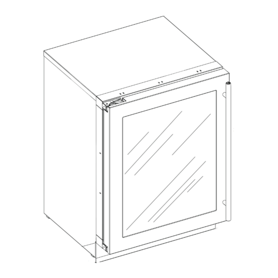
Page 9: Product Dimensions
USER GUIDE SAFETY • INSTALLATION & INTEGRATION • OPERATING INSTRUCTIONS • MAINTENANCE • SERVICE Product Dimensions Not Including Handle 23-7/16" (590 mm)* 33-11/16" to 34-11/16" (856 to 881 mm) 23-5/8" (600 mm) 3-5/8" to 4-5/8" (92 mm to 118 mm) Product Dimensions 1... -
Page 10: Side-By-Side Installation
USER GUIDE SAFETY • INSTALLATION & INTEGRATION • OPERATING INSTRUCTIONS • MAINTENANCE • SERVICE Side-by-Side Installation Hinge-by-Hinge Installation (Mullion) When installing two units hinge-by-hinge, 13/16" (22 mm) is required for integrated models. Additional space may be OTHER SITE REQUIREMENTS needed for any knobs, pulls or handles installed. Side-by-Side Installation Units must operate from separate, properly grounded 13/16"... -
Page 11: Anti-Tip Bracket
USER GUIDE SAFETY • INSTALLATION & INTEGRATION • OPERATING INSTRUCTIONS • MAINTENANCE • SERVICE Anti-Tip Bracket 5. Using a 3/32" drill bit, drill 3 pilot holes 5/8" (16 mm) deep into bottom of counter top. Use the anti-tip bracket as a template. CAUTION 6. - Page 12 USER GUIDE u-line.com SAFETY • INSTALLATION & INTEGRATION • OPERATING INSTRUCTIONS • MAINTENANCE • SERVICE 5. Using a 3/32" drill bit, drill 3 pilot holes 5/8" (16 mm) deep into cabinetry frame using the anti-tip bracket as a template. 6. Install the 3 remaining 3 #8x5/8" screws into the plate using a #2 Phillips head screwdriver.
-
Page 13: General Installation
USER GUIDE SAFETY • INSTALLATION & INTEGRATION • OPERATING INSTRUCTIONS • MAINTENANCE • SERVICE General Installation INSTALLATION 1. Plug in the power/electrical cord. LEVELING INFORMATION 1. Use a level to confirm 2. Gently push the unit into position. Be careful not to the unit is level. -
Page 14: Integrated Grille - Plinth Dimensions
3. Apply double sided tape to the backside of the integrated grill (plinth strip/base fascia). Use the diagram below for reference. U-Line recommends ™ ™ tape, a high strength bonding tape. -
Page 15: Grille - Plinth Installation
USER GUIDE SAFETY • INSTALLATION & INTEGRATION • OPERATING INSTRUCTIONS • MAINTENANCE • SERVICE Grille - Plinth Installation REMOVING AND INSTALLING GRILLE (PLINTH STRIP/BASE FASCIA) WARNING Disconnect electric power to the unit before removing the grille (plinth strip/base fascia). When using the unit, the grille (plinth strip/base fascia) must be installed. -
Page 16: Door Swing
USER GUIDE SAFETY • INSTALLATION & INTEGRATION • OPERATING INSTRUCTIONS • MAINTENANCE • SERVICE Door Swing Wall For Integrated models that are installed adjacent to a wall, 1/2" (13 mm) 1/2" (13 mm) clearance is recommended from wall on hinge side to allow the door to open 90°. Allow for additional space for any knobs or pulls installed on the integrated panel/frame. - Page 17 3. Once cover is removed, slide hinge pin into hole as shown. Pin should slide into place, stopping the door at Your U-Line unit was shipped to you with the optional 90° 90°; if the pin does not go into the hole shown, hold pin.
-
Page 18: Door Alignment And Adjustment
USER GUIDE SAFETY • INSTALLATION & INTEGRATION • OPERATING INSTRUCTIONS • MAINTENANCE • SERVICE Door Adjustments 4. The wrap hinges on top of the door. Carefully pull wrap away and then up. See below. DOOR ALIGNMENT AND ADJUSTMENT Align and adjust the door if it is not level or is not sealing Step 2 properly. -
Page 19: First Use
USER GUIDE SAFETY • INSTALLATION & INTEGRATION • OPERATING INSTRUCTIONS • MAINTENANCE • SERVICE First Use All U-Line controls are preset at the factory. Initial startup requires no adjustments. NOTICE U-Line recommends allowing the unit to run overnight before loading with product. -
Page 20: Control Operation
USER GUIDE SAFETY • INSTALLATION & INTEGRATION • OPERATING INSTRUCTIONS • MAINTENANCE • SERVICE Control Operation Alert Up Down Light Power Used CONTROL FUNCTION GUIDE FUNCTION COMMAND DISPLAY/OPTIONS ON/OFF Press and release Unit will immediately turn ON or OFF. Press and release to leave interior Toggle lights Glass door wine and beverage centers only. -
Page 21: Sabbath Mode
The unit will still maintain internal temperatures and set points. View a full list of Star-K certified U-Line units at www.star-k.org. To enable Sabbath Mode: 1. Press (4) and hold for ten seconds and release (the °F/°C symbol will flash briefly at the end of the ten... -
Page 22: Airflow And Product Loading
Do not install the unit behind a door. When properly loaded, your U-Line unit will store up to 123 (12 oz. [330 ml]) cans or 79 (12 oz. [330 ml]) bottles and 10 (750 ml) bottles of wine. -
Page 23: U-Line Wine Guide
YOUNG wine OLD wine LIGHT-BODIED wine FULL-BODIED wine Any step back in quality will be noticed. If a fine wine is tasted prior to a lesser wine, many of the fine wine’s subtle qualities may be missed. U-Line Wine Guide 1... - Page 24 Great Bordeaux’s may have as much as a 10-year plateau before fading. Myth 4: Wine color does not change with aging. Truth: As red wines age they get lighter in color while whites get darker. U-Line Wine Guide 2...
-
Page 25: Ideal Wine Storage Considerations
Wines can become flat or tired when voids and vacuums are created inside the wine bottle. In order to create voids and vacuums within a liquid, aggressive motion or shaking of the wine bottle would have to occur. U-Line Wine Guide 3... - Page 26 Approximately 45°F (7°C) Sparkling ® Wine Captain Models - A Touch of Elegance In 1985 U-Line was the first North American appliance manufacturer to develop a residential wine storage unit, ® ® the Wine Captain . Each U-Line Wine Captain...
-
Page 27: Recommended Wine Storage
Specially designed horizontal wine racks properly position the bottles so the wine remains in contact with the cork, which ensures the cork does not become dry. U-Line recommends arranging wine bottles as shown in the illustrations below. Rack 1: Use These... -
Page 28: Interior Shelves
USER GUIDE SAFETY • INSTALLATION & INTEGRATION • OPERATING INSTRUCTIONS • MAINTENANCE • SERVICE Interior Shelves CAUTION REMOVING AND INSTALLING GLASS SHELVES Clips MUST be installed with the ribbed side Adjusting Interior Shelves down. Failure to do so may result in shelf or unit Models equipped with glass shelves have an adjustable damage. -
Page 29: Maintenance
USER GUIDE SAFETY • INSTALLATION & INTEGRATION • OPERATING INSTRUCTIONS • • SERVICE MAINTENANCE Cleaning Integrated Models To clean integrated panels, use household cleaner per the EXTERIOR CLEANING cabinet manufacturer’s recommendation. Stainless Models Stainless door panels and handles can discolor when INTERIOR CLEANING exposed to chlorine gas, pool chemicals, saltwater or Disconnect power to the unit. - Page 30 USER GUIDE SAFETY • INSTALLATION & INTEGRATION • OPERATING INSTRUCTIONS • • SERVICE MAINTENANCE NOTICE The drain pan was not designed to capture the water created when manually defrosting. To prevent water from overflowing the drain pan and possibly damaging water sensitive flooring, the unit must be removed from cabinetry.
-
Page 31: Cleaning Condenser
USER GUIDE SAFETY • INSTALLATION & INTEGRATION • OPERATING INSTRUCTIONS • MAINTENANCE • SERVICE Cleaning Condenser INTERVAL - EVERY SIX MONTHS To maintain operational efficiency, keep the front grille (plinth strip/base fascia) free of dust and lint, and clean the condenser when necessary. Depending on environmental conditions, more or less frequent cleaning may be necessary. -
Page 32: Wine Rack Installation
USER GUIDE SAFETY • INSTALLATION & INTEGRATION • OPERATING INSTRUCTIONS • MAINTENANCE • SERVICE Wine Rack Installation To insert wine racks in the cabinet: 1. Align the left and right rack channels with the tracks in To remove wine racks for cleaning: the cabinet. -
Page 33: Extended Non-Use
If the unit will be exposed to temperatures of 40°F (5°C) or less, the steps above must be followed. For questions regarding winterization, please call U-Line at 414.354.0300. CAUTION Damage caused by freezing temperatures is not covered by the warranty. -
Page 34: Troubleshooting Guide
• Evaporator: Refrigerant flowing through an evaporator may sound like boiling liquid. BEFORE CALLING FOR SERVICE If you think your U-Line product is malfunctioning, read • Condenser Fan: Air moving through a condenser may the CONTROL OPERATION section to clearly understand be heard. -
Page 35: Checking Product Temperature
USER GUIDE SAFETY • INSTALLATION & INTEGRATION • OPERATING INSTRUCTIONS • MAINTENANCE • SERVICE 6. After 24 hours, check the temperature of the water. If Problem Possible Cause and Remedy required, adjust the temperature control in a small Digital Display A factory test mode may be enabled. -
Page 36: Wire Diagram
USER GUIDE SAFETY • INSTALLATION & INTEGRATION • OPERATING INSTRUCTIONS • MAINTENANCE • SERVICE Wire Diagram Wire Diagram 1... -
Page 37: Product Liability
The part that caused the damage must be returned to U-Line in its entirety. The part must be clearly labeled with the serial number of the unit it was removed from, the date, and the servicer who removed the part. -
Page 38: Warranty Claims
• Final Billing – Remodel • Narda (or equivalent) form or submitted online at Noting all of the following on the warranty claim will be www.u-line.com considered proof of purchase, hard copy will not be required: • 60 day submittal deadline from date of completed service •... - Page 39 Parts U-2224BEVS-00A Item Description U-Line P/N Anti tip bracket w/screws 80-54012-00 Back panel 80-54086-00 Compressor eletricals only 80-54149-00 Compressor w/electricals 80-54150-00 Condenser 80-54427-00 Condenser fan w/screws 80-54014-00 Display module 80-54493-00 Door assembly w/hinges 80-54158-00 Drain pan w/double sided tape 80-54002-00...
-
Page 40: Ordering Replacement Parts
Warranty parts will be shipped at no charge after U-Line confirms warranty status. Please provide the model, serial number, part number and part description. Some parts will require color or voltage information. - Page 41 Never use a torch on a fully charged refrigeration system. Never substitute U-Line OEM replacement parts or methods of construction. R-600a must be stored and transported in Technician must observe all federal, state and local laws regarding refrigerants.
- Page 42 USER GUIDE SAFETY • INSTALLATION & INTEGRATION • OPERATING INSTRUCTIONS • MAINTENANCE • SERVICE R-600A SPECIFICATIONS/LABELING WARNING R-600a equipped products are labeled (both the unit and the compressor). Only skilled and well trained service technicians permitted to service R-600a equipped products. R-600a is colorless and odorless.
-
Page 43: Leak Detection
USER GUIDE SAFETY • INSTALLATION & INTEGRATION • OPERATING INSTRUCTIONS • MAINTENANCE • SERVICE Evacuate/reclaim via the piecing pliers to ensure the When re-brazing, the system must be purged with dry system is empty of R-600a before any system work is nitrogen and at least one access point open to the performed. - Page 44 USER GUIDE SAFETY • INSTALLATION & INTEGRATION • OPERATING INSTRUCTIONS • MAINTENANCE • SERVICE The low side of the refrigeration system (evaporator, Proper ventilation during service is required. compressor and suction line) must be leak tested with the compressor off (equalized pressure). Never apply a torch to a charged R-600a refrigeration system.
-
Page 45: Refrigeration System Diagnosis Guide
USER GUIDE SAFETY • INSTALLATION & INTEGRATION • OPERATING INSTRUCTIONS • MAINTENANCE • SERVICE System Diagnosis Guide REFRIGERATION SYSTEM DIAGNOSIS GUIDE System Suction Suction Compressor Condenser Capillary Evaporator Wattage Condition Pressure Line Discharge Tube Normal Normal Slightly below Very hot Very hot Warm Cold... -
Page 46: Compressor Specifications
USER GUIDE SAFETY • INSTALLATION & INTEGRATION • OPERATING INSTRUCTIONS • MAINTENANCE • SERVICE Compressor Specifications OVERLOAD PROTECTOR STARTING RELAY DANGER Electrocution can cause death or serious injury. Burns from hot or cold surfaces can cause serious injury. Take precautions when servicing RELAY COVER CAPACITOR this unit. -
Page 47: Troubleshooting - Extended
USER GUIDE SAFETY • INSTALLATION & INTEGRATION • OPERATING INSTRUCTIONS • MAINTENANCE • SERVICE Troubleshooting - Extended Component failure issues can be identified through service mode menu #19, “Component Testing.” Individual SPECIFIC ERRORS AND ISSUES components can be switched on and off to check for both proper function of a specific component and also delivery The technically advanced diagnostic capabilities of the of supply voltage to the components through the relays... -
Page 48: Main Control
USER GUIDE SAFETY • INSTALLATION & INTEGRATION • OPERATING INSTRUCTIONS • MAINTENANCE • SERVICE REFRIGERATION SYSTEM DIAGNOSIS GUIDE System Suction Suction Compressor Condenser Capillary Evaporator Wattage Condition Pressure Line Discharge Tube Normal Normal Slightly below Very hot Very hot Warm Cold Normal room... - Page 49 USER GUIDE SAFETY • INSTALLATION & INTEGRATION • OPERATING INSTRUCTIONS • MAINTENANCE • SERVICE NOTICE Check Voltage Alert Customer No Voltage Frequently toggling the compressor relay could At Wall Outlet Of Power Failure force the compressor into overload. The compressor will automatically deactivate during Voltage an overload and will remain deactivated until the overload switch cools.
-
Page 50: Reed Switch
USER GUIDE SAFETY • INSTALLATION & INTEGRATION • OPERATING INSTRUCTIONS • MAINTENANCE • SERVICE THERMISTOR FAILURE Zone Thermistor If the zone thermistor fails, the unit will continue to operate on a preset time interval of 10 minutes on and 30 minutes off. - Page 51 USER GUIDE SAFETY • INSTALLATION & INTEGRATION • OPERATING INSTRUCTIONS • MAINTENANCE • SERVICE Control Operation - Service UI BUTTON LAYOUT Hidden Button -Accesses Service Menu -No LED Up Button -Increases temperature -Navigates through service menu Down Button -Decreases temperature -Navigates through service menu -LED activated with button activation Light Button...
-
Page 52: Service Mode
USER GUIDE SAFETY • INSTALLATION & INTEGRATION • OPERATING INSTRUCTIONS • MAINTENANCE • SERVICE CONTROL FUNCTION QUICK GUIDE FUNCTION COMMAND DISPLAY/OPTIONS ON/OFF Press and release Unit will immediately turn ON or OFF Press and release to leave interior light Glass door wine captains and beverage centers Toggle lights on for 3 hours only. - Page 53 USER GUIDE SAFETY • INSTALLATION & INTEGRATION • OPERATING INSTRUCTIONS • MAINTENANCE • SERVICE Service Mode Guide Number Service Mode Menu Item To Navigate/Access View thermistor #1 cabinet temp no offsets Use up/down to access and light bulb key to view View thermistor #2 evaporator no offsets Use up/down to access and light bulb key to view View thermistor #3 ambient no offsets...
- Page 54 USER GUIDE SAFETY • INSTALLATION & INTEGRATION • OPERATING INSTRUCTIONS • MAINTENANCE • SERVICE SERVICE MODE GUIDE DEFROST INTERVAL ADJUST — 3 TO 24 HOURS THERMISTOR 1 — TEMPERATURE This will adjust the interval between defrosts from 3 to This will show the pure thermistor reading with no 24 hours.
-
Page 55: Defrost Information
USER GUIDE SAFETY • INSTALLATION & INTEGRATION • OPERATING INSTRUCTIONS • MAINTENANCE • SERVICE INDIVIDUAL COMPONENT TOGGLE RESTORE FACTORY DEFAULTS Relay #2. Will restore all adjustable functions to their factory settings. Relay #3. Will start the ice maker module and forward it through a full harvest cycle Relay #4. -
Page 56: Control Defaults
USER GUIDE SAFETY • INSTALLATION & INTEGRATION • OPERATING INSTRUCTIONS • MAINTENANCE • SERVICE Control Defaults Default Value Fahrenheit/Celsius* °F °C Defrost Duration Minutes Next Defrost Hours Thermistor Four OFFSET** — Thermistor Three OFFSET** — Thermistor Two OFFSET** — Thermistor One OFFSET** —... -
Page 57: Thermistor Failure
USER GUIDE SAFETY • INSTALLATION & INTEGRATION • OPERATING INSTRUCTIONS • MAINTENANCE • SERVICE Thermistors Thermistor Resistance Data Nominal Resistance Temp (F) Temp (C) Thermistors are used for various temperature readings. (OHMS)* Thermistors provide reliable temperature readings using a 169157 resistance which varies based on surrounding 121795 temperatures. - Page 58 USER GUIDE SAFETY • INSTALLATION & INTEGRATION • OPERATING INSTRUCTIONS • MAINTENANCE • SERVICE Defrost These units are frost free technology Model Length/ Stop Between Minutes Point Defrost Time 2218R/WC 2224BEV/R/WC 3018R/WC 1224DWR 1224WC 3024DWR/FZR/BEV/R 3036BVWC/RR/WCWC C01224F C029F 1224RF Defrost 1...
-
Page 59: Remove Fan And Cover
USER GUIDE Remove Fan and Cover Remove insulating foam from refrigerant line pass- through hole as needed to gain clearance for fan plug. CONVECTION COOLING Remove internal shelving. This unit is equipped with an advanced convection cooling system. Convection cooling stabilizes cabinet temperature, Remove rear shelf clips, fronts can remain. - Page 60 USER GUIDE 14. Remove and replace fan. Take special care to properly route fan wire. NOTICE Fan must be oriented to pull air in through lower evaporator cover vents and push air out at fan mounting location. 15. Installation is the reverse of removal. 16.
-
Page 61: One Year Limited Warranty
For products installed and used for normal residential use, material cosmetic defects are included in this warranty, with coverage limited to 60 days from the date of original purchase. All service provided by U-Line under the above warranty must be performed by a U-Line factory authorized servicer, unless otherwise specified by U-Line.