Table of Contents
Troubleshooting

Related Manuals for U-Line U-2224ZWC


Summary of Contents for U-Line U-2224ZWC
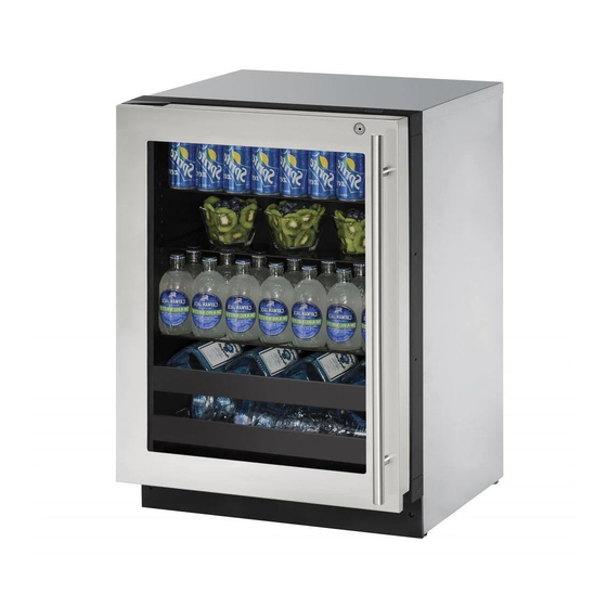
- Page 1 USER GUIDE & SERVICE MANUAL SAFETY • INSTALLATION & INTEGRATION • OPERATING INSTRUCTIONS • MAINTENANCE • SERVICE RIGHT PRODUCT. RIGHT PLACE. RIGHT TEMPERATURE. SINCE 1962. 2000 Series 2224ZWC 24" Dual Zone Wine Captain ® • •...
-
Page 2: Table Of Contents
Grille / Plinth Installation Compressor Specifications Door Swing Troubleshooting Extended Door Stop Control Quick Guide Door Adjust Thermistor Wood Trim Finishing Defrost Operating Instructions First Use Control Operation Sabbath Mode Airflow and Product Loading U-Line Wine Guide Recommended Wine Storage Maintenance Cleaning... - Page 3 1. U-Line Customer Care must be contacted immediately at +1.800.779.2547. 2. Service or repairs performed on the unit without prior written approval from U-Line is not permitted. If the unit has been altered or repaired in the field without prior written approval from U-Line, claims will not be eligible.
-
Page 4: Safety And Warning
USER GUIDE u-line.com SAFETY • INSTALLATION & INTEGRATION • OPERATING INSTRUCTIONS • MAINTENANCE • SERVICE Safety and Warning DANGER NOTICE This unit contains R600a (Isobutane) which is a Please read all instructions before installing, flammable hydrocarbon. It is safe for regular operating, or servicing the appliance. -
Page 5: Disposal And Recycling
USER GUIDE u-line.com SAFETY • INSTALLATION & INTEGRATION • OPERATING INSTRUCTIONS • MAINTENANCE • SERVICE Disposal and Recycling DANGER RISK OF CHILD ENTRAPMENT. Before you throw away your old refrigerator or freezer, take off the doors and leave shelves in place so children may not easily climb inside. -
Page 6: Environmental Requirements
USER GUIDE u-line.com SAFETY • INSTALLATION & INTEGRATION • OPERATING INSTRUCTIONS • MAINTENANCE • SERVICE Environmental Requirements This model is intended for indoor/interior applications only and is not to be used in installations that are open/ exposed to natural elements. - Page 7 USER GUIDE u-line.com SAFETY • INSTALLATION & INTEGRATION • OPERATING INSTRUCTIONS • MAINTENANCE • SERVICE Electrical WARNING SHOCK HAZARD — Electrical Grounding Required. Never attempt to repair or perform maintenance on the unit until the electricity has been disconnected. Never remove the round grounding prong from the plug and never use a two-prong grounding adapter.
-
Page 8: Cutout Dimensions
SAFETY • INSTALLATION & INTEGRATION • OPERATING INSTRUCTIONS • MAINTENANCE • SERVICE Cutout Dimensions PREPARE SITE Your U-Line product has been designed exclusively for a built-in installation. When built-in, your unit does not require additional air space for top, sides, or rear. -
Page 9: Product Dimensions
USER GUIDE u-line.com SAFETY • INSTALLATION & INTEGRATION • OPERATING INSTRUCTIONS • MAINTENANCE • SERVICE Product Dimensions Not Including Handle 23-7/16" (590 mm)* 33-11/16" to 34-11/16" (856 to 881 mm) 23-5/8" (600 mm) 3-5/16" (84 mm) Product Dimensions 1... -
Page 10: Side By Side Installation
USER GUIDE u-line.com SAFETY • INSTALLATION & INTEGRATION • OPERATING INSTRUCTIONS • MAINTENANCE • SERVICE Side-by-Side Installation Hinge-by-Hinge Installation (Mullion) When installing two units hinge-by-hinge, 13/16" (22 mm) OTHER SITE REQUIREMENTS is required for integrated models. Additional space may be Side-by-Side Installation needed for any knobs, pulls or handles installed. -
Page 11: Anti-Tip Bracket
USER GUIDE u-line.com SAFETY • INSTALLATION & INTEGRATION • OPERATING INSTRUCTIONS • MAINTENANCE • SERVICE Anti-Tip Bracket SIDE MOUNT Left Hinged Cabinet Right Hinged Cabinet CAUTION The anti-tip bracket must be installed to prevent the unit from tipping when doors are fully opened or excess weight is placed on the front of the unit. -
Page 12: General Installation
USER GUIDE u-line.com SAFETY • INSTALLATION & INTEGRATION • OPERATING INSTRUCTIONS • MAINTENANCE • SERVICE General Installation INSTALLATION 1. Plug in the power/electrical cord. LEVELING INFORMATION 1. Use a level to confirm 2. Gently push the unit into position. Be careful not to the unit is level. -
Page 13: Integrated Grille / Plinth Dimensions
3. Apply double sided tape to the backside of the integrated grill (plinth strip/base fascia). Use the diagram below for reference. U-Line recommends ™ ™ tape, a high strength bonding tape. -
Page 14: Grille / Plinth Installation
USER GUIDE u-line.com SAFETY • INSTALLATION & INTEGRATION • OPERATING INSTRUCTIONS • MAINTENANCE • SERVICE Grille - Plinth Installation REMOVING AND INSTALLING GRILLE (PLINTH STRIP/BASE FASCIA) WARNING Disconnect electric power to the unit before removing the grille (plinth strip/base fascia). -
Page 15: Door Swing
USER GUIDE u-line.com SAFETY • INSTALLATION & INTEGRATION • OPERATING INSTRUCTIONS • MAINTENANCE • SERVICE Door Swing Wall For Integrated models that are installed adjacent to a wall, 1/4" (6 mm) 1/4" (6 mm) clearance is recommended from wall on hinge side to allow the door to open 90°. -
Page 16: Door Stop
3. Once cover is removed, slide hinge pin into hole as shown. Pin should slide into place, stopping the door at Your U-Line unit was shipped to you with the optional 90° 90°; if the pin does not go into the hole shown, hold pin. -
Page 17: Door Adjust
USER GUIDE u-line.com SAFETY • INSTALLATION & INTEGRATION • OPERATING INSTRUCTIONS • MAINTENANCE • SERVICE Door Adjustments DOOR ALIGNMENT AND ADJUSTMENT Align and adjust the door if it is not level or is not sealing properly. If the door is not sealed, the unit may not cool... - Page 18 USER GUIDE u-line.com SAFETY • INSTALLATION & INTEGRATION • OPERATING INSTRUCTIONS • MAINTENANCE • SERVICE 3. Using T-25 Torx bit loosen screw #1 and remove screw #2 on top and bottom hinge. Slide and remove the door from unit. Completely remove screw #1 on top and bottom.
-
Page 19: Wood Trim Finishing
Not following this warning may cause the inner liner of the unit to have a permanent odor, which the warranty will not cover. ® U-Line recommends Minwax Brand Water Based Stains ® and Minwax Polycrylic Protective Finish. -
Page 20: First Use
USER GUIDE u-line.com SAFETY • INSTALLATION & INTEGRATION • OPERATING INSTRUCTIONS • MAINTENANCE • SERVICE First Use All U-Line controls are preset at the factory. Initial startup requires no adjustments. NOTICE U-Line recommends allowing the unit to run overnight before loading with product. -
Page 21: Control Operation
USER GUIDE u-line.com SAFETY • INSTALLATION & INTEGRATION • OPERATING INSTRUCTIONS • MAINTENANCE • SERVICE Control Operation Up Down Light Power Auxiliary LED CONTROL FUNCTION GUIDE FUNCTION COMMAND DISPLAY/OPTIONS ON/OFF Press and release Unit will immediately turn ON or OFF. -
Page 22: Sabbath Mode
The unit will still maintain internal temperatures and set points. View a full list of Star-K certified U-Line units at www.star-k.org. To enable Sabbath Mode: 1. Press (4) and hold for ten seconds and release (the °F/°C symbol will flash briefly at the end of the ten... -
Page 23: Airflow And Product Loading
Anything in direct contact with the evaporator is subject to freezing. When properly loaded, your U-Line unit will store up to 43 (750 ml) bottles of wine. Airflow and Product Loading 1... -
Page 24: U-Line Wine Guide
YOUNG wine OLD wine LIGHT-BODIED wine FULL-BODIED wine Any step back in quality will be noticed. If a fine wine is tasted prior to a lesser wine, many of the fine wine’s subtle qualities may be missed. U-Line Wine Guide 1... - Page 25 Great Bordeaux’s may have as much as a 10-year plateau before fading. Myth 4: Wine color does not change with aging. Truth: As red wines age they get lighter in color while whites get darker. U-Line Wine Guide 2...
- Page 26 Wines can become flat or tired when voids and vacuums are created inside the wine bottle. In order to create voids and vacuums within a liquid, aggressive motion or shaking of the wine bottle would have to occur. U-Line Wine Guide 3...
- Page 27 Approximately 45°F (7°C) Sparkling ® Wine Captain Models - A Touch of Elegance In 1985 U-Line was the first North American appliance manufacturer to develop a residential wine storage unit, ® ® the Wine Captain . Each U-Line Wine Captain...
-
Page 28: Recommended Wine Storage
Specially designed horizontal wine racks properly position the bottles so the wine remains in contact with the cork, which ensures the cork does not become dry. U-Line recommends arranging wine bottles as shown in the illustrations below. Use These Racks For Larger... -
Page 29: Cleaning
USER GUIDE u-line.com SAFETY • INSTALLATION & INTEGRATION • OPERATING INSTRUCTIONS • MAINTENANCE • SERVICE Cleaning Integrated Models To clean integrated panels, use household cleaner per the EXTERIOR CLEANING cabinet manufacturer’s recommendations. Stainless Models Stainless door panels, handles and frames can discolor... - Page 30 USER GUIDE u-line.com SAFETY • INSTALLATION & INTEGRATION • OPERATING INSTRUCTIONS • MAINTENANCE • SERVICE NOTICE The drain pan was not designed to capture the water created when manually defrosting. To prevent water from overflowing the drain pan, and possibly damaging water sensitive flooring, the unit must be removed from cabinetry.
-
Page 31: Cleaning Condenser
USER GUIDE u-line.com SAFETY • INSTALLATION & INTEGRATION • OPERATING INSTRUCTIONS • MAINTENANCE • SERVICE Cleaning Condenser INTERVAL - EVERY SIX MONTHS To maintain operational efficiency, keep the front grille (plinth strip/base fascia) free of dust and lint, and clean the condenser when necessary. -
Page 32: Wine Rack Installation
USER GUIDE u-line.com SAFETY • INSTALLATION & INTEGRATION • OPERATING INSTRUCTIONS • MAINTENANCE • SERVICE Wine Rack Installation To insert wine racks in the cabinet: 1. Align the left and right rack channels with the tracks in To remove wine racks for cleaning: the cabinet. -
Page 33: Extended Non-Use
If the unit will be exposed to temperatures of 40°F (5°C) or less, the steps above must be followed. For questions regarding winterization, please call U-Line at +1.800.779.2547. CAUTION Damage caused by freezing temperatures is not covered by the warranty. -
Page 34: Troubleshooting
• Evaporator: Refrigerant flowing through an evaporator may sound like boiling liquid. BEFORE CALLING FOR SERVICE If you think your U-Line product is malfunctioning, read • Condenser Fan: Air moving through a condenser may the CONTROL OPERATION section to clearly understand be heard. - Page 35 USER GUIDE u-line.com SAFETY • INSTALLATION & INTEGRATION • OPERATING INSTRUCTIONS • MAINTENANCE • SERVICE 6. After 24 hours, check the temperature of the water. If Problem Possible Cause and Remedy required, adjust the temperature control in a small Digital Display A factory test mode may be enabled.
-
Page 36: Warranty 1
One Year Limited Warranty For one year from the date of original purchase, this U-Line product warranty covers all parts and labor to repair or replace any part of the product that proves to be defective in materials or workmanship. For products installed and used for normal residential use, material cosmetic defects are included in this warranty, with coverage limited to 60 days from the date of original purchase. -
Page 37: Wire Diagram
USER GUIDE u-line.com SAFETY • INSTALLATION & INTEGRATION • OPERATING INSTRUCTIONS • MAINTENANCE • SERVICE Wire Diagram Wire Diagram 1... -
Page 38: Product Liability
The part that caused the damage must be returned to U-Line in its entirety. The part must be clearly labeled with the serial number of the unit it was removed from, the date, and the servicer who removed the part. -
Page 39: Warranty Claims
USER GUIDE u-line.com SAFETY • INSTALLATION & INTEGRATION • OPERATING INSTRUCTIONS • MAINTENANCE • SERVICE Warranty Claims warranty status. We also accept the following information to verify warranty status: The following information defines the parameters for filing a warranty claim: •... -
Page 40: Parts
Parts U-2224ZWCS-00B Item Description U-Line P/N Anti tip brackets w/screws 80-54012-00 Back panel 80-54086-00 Compressor eletricals only 80-54149-00 Compressor w/electricals 80-54193-00 Condenser 80-54090-00 Condenser fan w/screws 80-54014-00 Display module 80-54007-00 Door assembly w/o hinges 80-54185-00 Door gasket 80-54039-00 10 Drain pan w/double sided tape... -
Page 41: Ordering Replacement Parts
Warranty parts will be shipped at no charge after U-Line confirms warranty status. Please provide the model, serial number, part number and part description. Some parts will require color or voltage information. -
Page 42: System Diagnosis Guide
USER GUIDE u-line.com SAFETY • INSTALLATION & INTEGRATION • OPERATING INSTRUCTIONS • MAINTENANCE • SERVICE System Diagnosis Guide REFRIGERATION SYSTEM DIAGNOSIS GUIDE System Suction Suction Compressor Condenser Capillary Evaporator Wattage Condition Pressure Line Discharge Tube Normal Normal Slightly below Very hot... -
Page 43: Compressor Specifications
USER GUIDE u-line.com SAFETY • INSTALLATION & INTEGRATION • OPERATING INSTRUCTIONS • MAINTENANCE • SERVICE Compressor Specifications OVERLOAD PROTECTOR STARTING RELAY DANGER Electrocution can cause death or serious injury. Burns from hot or cold surfaces can cause serious injury. Take precautions when servicing... -
Page 44: Troubleshooting Extended
Included in this section are some diagnostic tips and of • Solenoid Valves: An occasional clicking sound may be course, if additional help is required please contact the heard as solenoid valves are operated. U-Line Corp, “Customer Care Facility” at +1.800.779.2547 for assistance. Troubleshooting - Extended 1... - Page 45 USER GUIDE u-line.com SAFETY • INSTALLATION & INTEGRATION • OPERATING INSTRUCTIONS • MAINTENANCE • SERVICE TROUBLESHOOTING GUIDE Concern Potential Causes Suggested Remedy Not Cooling Compressor overheating Verify proper air flow through condenser. Is condenser clean? Confirm condenser fan operation. Confirm proper compressor operating voltage.Use #19, Component Testing in Service Mode.
- Page 46 USER GUIDE u-line.com SAFETY • INSTALLATION & INTEGRATION • OPERATING INSTRUCTIONS • MAINTENANCE • SERVICE MAIN CONTROL Testing The Main Control The main control board is very robust and is rarely the If the main control is suspected of being faulty, the cause of system issues.
- Page 47 USER GUIDE u-line.com SAFETY • INSTALLATION & INTEGRATION • OPERATING INSTRUCTIONS • MAINTENANCE • SERVICE CAUTION Precautions must be taken while working with live electrical equipment. Be sure to follow proper safety procedures while performing tests on live systems. REED SWITCH A reed switch is used to monitor door state.
- Page 48 USER GUIDE u-line.com SAFETY • INSTALLATION & INTEGRATION • OPERATING INSTRUCTIONS • MAINTENANCE • SERVICE Control Operation - Service UI BUTTON LAYOUT Hidden Button -Accesses Service Menu -No LED directly above. All LEDs turn on with button activation except #7.
- Page 49 USER GUIDE u-line.com SAFETY • INSTALLATION & INTEGRATION • OPERATING INSTRUCTIONS • MAINTENANCE • SERVICE CONTROL FUNCTION GUIDE FUNCTION COMMAND DISPLAY/OPTIONS ON/OFF Press and release Unit will immediately turn ON or OFF. Toggle lights Press and release Leave interior light on for 3 hours.
- Page 50 USER GUIDE u-line.com SAFETY • INSTALLATION & INTEGRATION • OPERATING INSTRUCTIONS • MAINTENANCE • SERVICE SERVICE MODE GUIDE 3. THERMISTOR 3 — BOTTOM ZONE This shows the pure thermistor reading with no Service Mode Menu Item offsets taken into account.
- Page 51 USER GUIDE u-line.com SAFETY • INSTALLATION & INTEGRATION • OPERATING INSTRUCTIONS • MAINTENANCE • SERVICE 13. ADJUST DEFROST DURATION — 0 TO 99 20. MODEL NUMBER INDICATOR MINUTES Displays the two-digit model number of the The length of the defrost can be adjusted 0 to 99 specific unit.
- Page 52 MODEL NUMBER 1. Disconnect the unit from power source. 2. Push and hold the U-Line button. 3. While still holding the U-Line button, plug the unit into the appropriate power source. 4. When the flashing digits appear (3-5 seconds), use the up and down arrow buttons to select the appropriate model number*.
- Page 53 USER GUIDE u-line.com SAFETY • INSTALLATION & INTEGRATION • OPERATING INSTRUCTIONS • MAINTENANCE • SERVICE Control Operation - Service 6...
- Page 54 USER GUIDE u-line.com SAFETY • INSTALLATION & INTEGRATION • OPERATING INSTRUCTIONS • MAINTENANCE • SERVICE Thermistors Thermistor three (Zone): Located along the right hand side wall in the bottom/right Thermistors are used for various temperature readings. compartment. It is used to maintain the operating Thermistors provide reliable temperature readings using a temperature within that zone.
- Page 55 USER GUIDE u-line.com SAFETY • INSTALLATION & INTEGRATION • OPERATING INSTRUCTIONS • MAINTENANCE • SERVICE Evaporator Thermistors If an evaporator thermistor fails the unit will rely on a preset defrost timer during defrost cycles. The unit will otherwise operate normally. Refer to defrost section.
-
Page 56: Defrost
USER GUIDE u-line.com SAFETY • INSTALLATION & INTEGRATION • OPERATING INSTRUCTIONS • MAINTENANCE • SERVICE Defrost The models below have automatic or frost free design and do not require manual defrosting under normal conditions. Defrost Settings Base Model Variant(s) Compressor Run Time...