Table of Contents
Advertisement
Quick Links
Advertisement
Table of Contents
Troubleshooting

Related Manuals for Miller Panther 307


Summary of Contents for Miller Panther 307
- Page 1 OM-4408 203 435A September 2002 Processes Stick (SMAW) Welding TIG (GTAW) Welding Flux Cored (FCAW) Welding Air Carbon Arc (CAC-A) Cutting and Gouging Description Engine Driven Welding Generator Panther 307/310 Visit our website at www.MillerWelds.com...
- Page 2 We know you don’t have time to do it any other way. That’s why when Niels Miller first started building arc welders in 1929, he made sure his products offered long-lasting value and superior quality.
-
Page 3: Table Of Contents
TABLE OF CONTENTS SECTION 1 – SAFETY PRECAUTIONS - READ BEFORE USING ......1-1. Symbol Usage . - Page 4 Belmont House Deakins Business Park, Blackburn Road Egerton, Bolton BL7 9RP Lancashire, England – United Kingdom Declares that this product: Panther 307/310 Conforms to the following Directives and Standards: Directives Low Voltage Directive: 73/23/EEC Machinery Directives: 98/37/EEC,91/368/EEC, 93/C 133/04, 93/68/EEC...
-
Page 5: Section 1 - Safety Precautions - Read Before Using
SECTION 1 – SAFETY PRECAUTIONS - READ BEFORE USING rom _nd_4/02 1-1. Symbol Usage Means Warning! Watch Out! There are possible hazards with this procedure! The possible hazards are shown in the adjoining symbols. This group of symbols means Warning! Watch Out! possible Y Marks a special safety message. -
Page 6: Engine Hazards
WELDING can cause fire or explosion. HOT PARTS can cause severe burns. D Allow cooling period before maintaining. Welding on closed containers, such as tanks, D Wear protective gloves and clothing when drums, or pipes, can cause them to blow up. Sparks working on a hot engine. -
Page 7: Additional Symbols For Installation, Operation, And Maintenance
READ INSTRUCTIONS. stopping engine. D Do not let low voltage and frequency caused by D Use only genuine MILLER replacement parts. low engine speed damage electric motors. D Perform engine maintenance and service D Do not connect 50 or 60 Hertz motors to the 100 Hertz receptacle according to this manual and the engine where applicable. -
Page 8: Principal Safety Standards
H.F. RADIATION can cause interference. ARC WELDING can cause interference. D High-frequency (H.F.) can interfere with radio D Electromagnetic energy can interfere with navigation, safety services, computers, and sensitive electronic equipment such as communications equipment. computers and computer-driven equipment D Have only qualified persons familiar with such as robots. -
Page 9: Section 2 - Definitions
SECTION 2 – DEFINITIONS 2-1. Warning Label Definitions (CE Models Only) Warning! Watch Out! There are possible hazards as shown by the symbols. Become trained and read the instructions before working on the machine or welding. Electric shock from welding electrode or wiring can kill. - Page 10 Warning! Watch Out! There are possible hazards as shown by the symbols. Do not smoke and keep matches and flames away from battery. Sparks can cause battery gases to explode. Battery explosion can blind and injure. Wear a face shield. Battery acid can burn skin.
- Page 11 Warning! Watch Out! There are possible hazards as shown by the symbols. Engine fuel plus flames or sparks can cause fire. Do not smoke while fueling or if near fuel. Stop engine before fueling. Do not fuel a hot engine. Use Diesel Fuel only.
- Page 12 Prior to 2002 Effective w/2002 Isuzu-Powered Unit Kubota-Powered Unit Read the instruction manual Isuzu-Powered Unit Engine oil drain port Coolant overflow tank drain port Radiator drain port Fuel tank drain port 203 950 Kubota-Powered Unit OM-4408 Page 8...
-
Page 13: Manufacturer's Rating Labels For Ce Products
2-2. Manufacturer’s Rating Labels For CE Products Notes Work like a Pro! Pros weld and cut safely. Read the safety rules at the beginning of this manual. OM-4408 Page 9... -
Page 14: Symbols And Definitions
2-3. Symbols And Definitions NOTE Some symbols are found only on CE products. Fast (Run, Weld/ Stop Engine Slow (Idle) Start Engine Power) Engine Oil Starting Aid Battery (Engine) Engine Oil Pressure Check Injectors/ Check Valve Protective Earth Fuel Pump Clearance (Ground) Certified/Trained... -
Page 15: Section 3 - Specifications
SECTION 3 – SPECIFICATIONS 3-1. Weld, Power, and Engine Specifications Weld Rated Maximum Generator Welding Fuel Output Welding Open-Circuit Power Engine Sound Level* Mode Capacity Range Output Voltage (OCV) Rating Kubota D905-B Prior To 2002: Water-Cooled, Single Phase Three-Cylinder, 7 kVA 65 dB(A) at 7m Four-Cycle, 110/220 V... -
Page 16: Volt-Ampere Curve
3-3. Volt-Ampere Curve The volt-ampere curve shows the minimum and maximum voltage and amperage output capabilities of the welding generator. Curves of all other settings fall between the curves shown. Max. Min. DC AMPERES 3-4. Generator Power Curve The ac generator power curves A. -
Page 17: Duty Cycle And Overheating
3-5. Duty Cycle and Overheating Duty cycle is the percentage of 10 minutes that unit can weld at rated load without overheating. Y Exceeding duty cycle can damage unit void warranty. % DUTY CYCLE 60% Duty Cycle at 280 Amperes DC 6 Minutes Welding 4 Minutes Resting 198 919... -
Page 18: Section 4 - Installation
SECTION 4 – INSTALLATION 4-1. Installing Welding Generator Y Do not weld on base. Welding on base can cause fuel tank fire or explosion. Bolt unit down using holes provided in base. Movement Y Always securely fasten weld- ing generator onto transport Y Do not lift unit from end. -
Page 19: Activating The Dry Charge Battery (If Applicable)
4-2. Activating The Dry Charge Battery (If Applicable) Remove battery from unit. Eye Protection – Safety Glasses Or Face Shield Rubber Gloves Vent Caps Sulfuric Acid Electrolyte (1.265 Specific Gravity) Well Fill each cell with electrolyte to bottom of well (maximum). Y Do not overfill battery cells. -
Page 20: Connecting The Battery
4-3. Connecting The Battery Isuzu-Powered Units Y Connect Negative (–) Cable Last. – Kubota-Powered Units Tools Needed: 12 mm 803 126 OM-4408 Page 16... -
Page 21: Engine Prestart Checks
4-4. Engine Prestart Checks Check radiator coolant level when fluid is low in recovery tank. 1/2 in Full (13 mm) Full Full Capacity Diesel w/Overflow Tank 6 L (6.4 qt) Full 803 126 mm) from top to allow room for expansion. Engine coolant is a mixture of water and Check all engine fluids daily. -
Page 22: Connecting To Weld Output Terminals
4-5. Connecting to Weld Output Terminals Y Stop engine. Positive (+) Weld Output Terminal Negative (–) Weld Output Ter- minal For Stick welding Direct Current Electrode Positive (DCEP), connect the electrode holder cable to Positive (+) weld output terminal and work cable to the Negative (–) output termi- nal. -
Page 23: Connecting To Remote Amperage Adjustment Receptacle
4-7. Connecting To Remote Amperage Adjustment Receptacle Remote Amperage Adjustment Receptacle (3-pin) Remote Amperage Control (Typical) Connect optional remote control to 3-pin receptacle. Panel/Remote Amperage Control Switch to select front panel or remote amperage control (see Section 5-1 or 5-2). 803 125 Notes OM-4408 Page 19... -
Page 24: Section 5 - Operating The Welding Generator
SECTION 5 – OPERATING THE WELDING GENERATOR 5-1. Front Panel Controls For 110 and 220 Volt Models Kubota Nameplate Shown Isuzu 114010366-00 Engine Lights Fuel Gauge To Start: Above 325 F: Place Engine Speed Switch in Use gauge to check fuel level. Battery Charging Light Run/Idle and turn Engine Control Switch to Weld Controls... -
Page 25: Front Panel Controls For 400 Volt Models
5-2. Front Panel Controls For 400 Volt Models Engine Lights Weld Controls Place switch in Run or Run/Idle position Amperage Adjustment Control when using generator power. Battery Charging Light Use this control to select the desired weld out- Light goes on if engine alternator is not charg- Place switch in Run position to operate put from 30 to 300 amperes. -
Page 26: Section 6 - Operating Auxiliary Equipment
SECTION 6 – OPERATING AUXILIARY EQUIPMENT 6-1. Using the AC Generator 400 Volt Models 110 and 220 Volt Models Ground Fault Circuit Interrupter Protected by GFCI breaker MCCB3, this weld amperage being used (see Sections (GFCI) MCCB3 receptacle supplies AC 50 HZ power ac- 6-2 and 6-3). - Page 27 Notes Work like a Pro! Pros weld and cut safely. Read the safety rules at the beginning of this manual. OM-4408 Page 23...
-
Page 28: Section 7 - Maintenance And Troubleshooting
SECTION 7 – MAINTENANCE AND TROUBLESHOOTING 7-1. Routine Maintenance Note Follow the storage procedure in the Engine Manual if the unit will not be used for an extended period of time. Y Stop engine before maintaining. See also Engine Manual and Maintenance Label. Recycle engine Service engine more often if used in severe condi-... -
Page 29: Maintenance Label For Isuzu Engine
500 h Change coolant and Replace fan belt. flush radiator. See Section 7-11. FUEL Repair or replace Drain sludge from fuel SLUDGE cracked cables. tank. See Section 7-7. 800 h Check valve clearance.* 1000 h Blow out or vacuum inside. During heavy service, clean monthly. -
Page 30: Maintenance Label For Kubota Engine
7-3. Maintenance Label For Kubota Engine 7-4. Optional Spark Arrestor Y Stop engine and let it cool down. Spark Arrestor The optional spark arrestor is self- cleaning and does not require any maintenance or service. Isuzu-Powered Units Kubota-Powered Units 802 656 OM-4408 Page 26... -
Page 31: Servicing Air Cleaner
7-5. Servicing Air Cleaner Y Stop engine. Y Do not run engine without air cleaner or with dirty element. En- gine damage caused by using a damaged element is not covered by the warranty. The air cleaner element can be cleaned but the dirt holding capacity of the filter is reduced with each cleaning. -
Page 32: Changing Engine Oil And Filter
7-6. Changing Engine Oil and Filter Kubota-Powered Units Isuzu-Powered Units Isuzu-Powered Units Kubota-Powered Units Tools Needed: 16 mm 803 126 Y Stop engine and let it cool down. Place drain pan under drain plug. Remove Fill crankcase with new oil up to full mark on plug and drain oil (see Engine Manual for dipstick (see Maintenance label for oil Oil Fill Cap... -
Page 33: Servicing Fuel System And Fuel Filter
7-7. Servicing Fuel System And Fuel Filter Tools Needed: Kubota-Powered Units Isuzu-Powered Units 803 126 Draining Water From Fuel Tank Draining Water from Fuel Filter And Loosen ring nut and remove filter cup (has element inside). Replacing Filter Element Y Stop engine and let it cool down be- Dump out cup and the filter element and fore servicing fuel system. -
Page 34: Adjusting Engine Speed (Kubota-Powered Units Only)
7-8. Adjusting Engine Speed (Kubota-Powered Units Only) After tuning engine, check engine speeds with a tachometer (see table). If necessary, adjust speeds as follows: ± 1800 100 rpm Start engine and run until warm. Turn V/A control to max. ± 3000 100 rpm Adjusting Idle Speed... -
Page 35: Overload Protection (Fuses)
7-9. Overload Protection (Fuses) Kubota-Powered Units Isuzu-Powered Units 803 126 Y Stop engine. sure Light turns On and the engine stops. If rized Service Agent determine the cause this condition occurs, stop the engine and and replace any necessary parts. When a fuse opens, it usually indicates have a factory authorized Service Agent Door Switch... -
Page 36: Overload Fuse Link And Internal Parts
7-10. Overload Fuse Link And Internal Parts Kubota-Powered Units Isuzu-Powered Units 803232 Y Stop engine. This fuse link protects the Glow Plugs and When a fuse opens, it usually indicates keeps them from burning out in case the AVR - Automatic Voltage Regulator that a more serious problem exists. -
Page 37: Servicing Engine Cooling System
7-11. Servicing Engine Cooling System Tools Needed: Kubota-Powered Units Isuzu-Powered Units Isuzu-Powered Units Kubota-Powered Units 803 126 Y Stop engine and let it cool down. cap. Place pan under drain port and open coolant specifications. Reinstall radiator drain valve. Drain and flush system with cap. -
Page 38: Section 8 - Troubleshooting
SECTION 8 – TROUBLESHOOTING 8-1. Troubleshooting A. Welding Trouble Remedy Indicator lights (glow plug, oil pressure, Battery is discharged. Check battery and recharge or replace as necessary. battery) do not turn on when starter Fusible link (FBL) is open. Check and replace fusible link (see Section 7-10). switch is ON. - Page 39 Trouble Remedy Amperage Adjustment Control does not Amperage Adjustment Control is defective or disconnected. Have Factory Authorized Service Agent change output check connections or replace control. Have Factory Authorized Service Agent check WCR (Weld Current Regulator board) and thyristor. No Remote Amperage control. Place Amperage Control switch in Remote position.
- Page 40 C. Engine Trouble Remedy Check battery voltage. Engine will not crank. Check battery connections and tighten if necessary. Have Factory Authorized Service Agent check Engine Control switch S1. Engine cranks, but does not start. Check fuel level (see Section 4-2). Open fuel valve (see Section 4-2).
- Page 41 Notes Work like a Pro! Pros weld and cut safely. Read the safety rules at the beginning of this manual. OM-4408 Page 37...
-
Page 42: Section 9 - Electrical Diagrams
SECTION 9 – ELECTRICAL DIAGRAMS STATOR AC.COIL(A) Y(5.5) Y(5.5) B(1.25) ROTOR AC.COIL(B) R(5.5) MAIN FIELD COIL R(5.5) B(1.25) WELDING COIL RX(A1) SCR(A) WELDING COIL ARMATURE COIL RX(B1) FIELD COIL SENSING SCR(B) COIL EXCITING EXCITER COIL W C R A V R Figure 9-1. - Page 43 SYMBOL PARTS NAME RECTIFIRE RX(A1) RECTIFIRE SCR(A) THYRISTOR RX(B1) RECTIFIRE SCR(B) THYRISTOR DCL(A) DC REACTOR DCL(B) DC REACTOR MCCB1 EARTH LEAKAGE BREAKER MCCB2,3 EARTH LEAKAGE BREAKER CON1 AC RECEPTACLE CON2,3 AC RECEPTACLE SLOW DOWN TIMER RESISTOR RX(A2) RECTIFIRE CURRENT REGULATOR SWRS REMOTE SELECTOR SWITCH WIRING COLOR TABLE...
- Page 44 Figure 9-2. Circuit Diagram for 400 Volt Welding Generator (110/230/380–415 Volt Receptacles) OM-4408 Page 40...
- Page 45 OM-4408 Page 41...
- Page 46 Figure 9-3. Circuit Diagram for Isuzu Engine OM-4408 Page 42...
- Page 47 OM-4408 Page 43...
- Page 48 Figure 9-4. Circuit Diagram for Kubota Engine OM-4408 Page 44...
- Page 49 OM-4408 Page 45...
-
Page 50: Section 10 - Run-In Procedure
SECTION 10 – RUN-IN PROCEDURE run_in1 8/01 10-1. Wetstacking Y Do perform run-in procedure at less than 20 volts weld output and do not exceed duty cycle or equip- ment damage may occur. Welding Generator Run diesel engines near rated volt- age and current during run-in period to properly seat piston rings and prevent wetstacking. -
Page 51: Run-In Procedure Using Load Bank
10-2. Run-In Procedure Using Load Bank Y Stop engine. Y Do not touch hot exhaust pipe, engine parts, or load bank/grid. Y Keep exhaust and pipe away from flammables. Y Do perform run-in procedure at less than 20 volts weld output and do not exceed duty cycle or equip- ment damage may occur. -
Page 52: Run-In Procedure Using Resistance Grid
10-3. Run-In Procedure Using Resistance Grid Y Stop engine. Y Do not touch hot exhaust pipe, engine parts, or load bank/grid. Y Keep exhaust and pipe away from flammables. Y Do perform run-in procedure at less than 20 volts weld output and do not exceed duty cycle or equip- ment damage may occur. -
Page 53: Section 11 - Generator Power Guidelines
SECTION 11 – GENERATOR POWER GUIDELINES 11-1. Selecting Equipment Generator Power Receptacles – Neutral Bonded To Frame 3-Prong Plug From Case Grounded Equipment 2-Prong Plug From Double Insulated Equipment Y Do not use 2-prong plug un- less equipment is double in- sulated. - Page 54 11-3. Grounding When Supplying Building Systems Equipment Grounding Terminal Grounding Cable GND/PE Use #10 AWG (2.6 mm ) or larger insulated copper wire. Ground Device Y Ground generator to system earth ground if supplying power to a premises (home, shop, farm) wiring system. Use ground device as stated in electrical codes.
- Page 55 11-5. Approximate Power Requirements For Industrial Motors Industrial Motors Rating Starting Watts Running Watts Split Phase 1/8 HP 1/6 HP 1225 1/4 HP 1600 1/3 HP 2100 1/2 HP 3175 Capacitor Start-Induction Run 1/3 HP 2020 1/2 HP 3075 3/4 HP 4500 1400 1 HP...
- Page 56 11-7. Approximate Power Requirements For Contractor Equipment Contractor Rating Starting Watts Running Watts Hand Drill 1/4 in 3/8 in 1/2 in Circular Saw 6-1/2 in 7-1/4 in 8-1/4 in 1400 1400 Table Saw 9 in 4500 1500 10 in 6300 1800 Band Saw 14 in...
- Page 57 11-8. Power Required To Start Motor Motor Start Code AC MOTOR Running Amperage VOLTS AMPS Motor HP CODE Motor Voltage PHASE To find starting amperage: Step 1: Find code and use table to find kVA/HP. If code is not listed, multiply running amperage by six to find starting amperage.
- Page 58 11-10. Typical Connections To Supply Standby Power Y Properly install and ground this equipment according to its Owner’s Manual and national, state, and local codes. Fused Utility Welding Disconnect Electrical Generator Transfer Switch Switch Service Output (If Required) Essential Loads Y Have only qualified persons perform Switch transfers the electrical load from Connect generator with temporary or perma-...
- Page 59 11-11. Selecting Extension Cord (Use Shortest Cord Possible) Cord Lengths for 120 Volt Loads Y If unit does not have GFCI receptacles, use GFCI-protected extension cord. Maximum Allowable Cord Length in ft (m) for Conductor Size (AWG)* Current Load (Watts) (Amperes) 350 (106) 225 (68)
-
Page 60: Section 12 - Parts List
SECTION 12 – PARTS LIST When ordering parts, please specify the model, serial number, and quantity. Figure 12-1. Generator Group 01144301 OM-4408 Page 56... - Page 61 Item Part Description Quantity Figure 12-1. Generator Group ..K2010010670 Stator Assy (110/220 Volt Models) ....K2010100370 Stator Assy (400 Volt Models) .
- Page 62 011443 Figure 12-2. Electric Group – 110/220 Volt Models OM-4408 Page 58...
- Page 63 Item Part Description Quantity Figure 12-2. Electric Group – 110/220 Volt Models ..K5110100790 Ground Fault Circuit Interruptor (GFCI) ... . K5110100780 Ground Fault Circuit Interruptor (GFCI) .
- Page 64 Item Part Description Quantity Figure 12-2. Electric Group – 110/220 Volt Models (continued) ..K4710101040 Wiring Harness Connect ....
- Page 65 Item Part Description Quantity Figure 12-3. Electric Group – 400 Volt Models ..K5010104430 Voltmeter .......
- Page 66 01144303 Figure 12-4. Absorber – Exhaust – Speed Control – Battery – Air Cleaner Group OM-4408 Page 62...
- Page 67 Item Part Description Quantity Figure 12-4. Absorber – Exhaust – Speed Control – Battery – Air Cleaner Group ..K4010025260 Absorber, Rubber ......
- Page 68 00230204 Figure 12-5. Cooling – Fuel – Oil Group – Isuzu Engine OM-4408 Page 64...
- Page 69 Item Part Description Quantity Figure 12-5. Cooling – Fuel – Oil Group – Isuzu Engine ..K5863013990 Radiator Ass’y ......
- Page 70 01144304 Figure 12-6. Cooling – Fuel – Oil Group – Kubota Engine OM-4408 Page 66...
- Page 71 Item Part Description Quantity Figure 12-6. Cooling – Fuel – Oil Group – Kubota Engine ..K1742872060 Radiator Assy ......
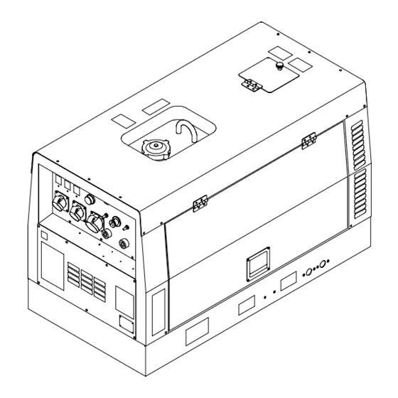
- Page 72 Figure 12-7. Frame – Enclosure Group OM-4408 Page 68...
- Page 73 Item Part Description Quantity Figure 12-7. Frame – Enclosure Group ..K3210024680 Frame, Base (Isuzu) .....
- Page 74 Item Part Description Quantity Figure 12-7. Frame – Enclosure Group (continued) ..K3210109480 Bracket, Center (Kubota) ....
- Page 75 Item Part Description Quantity Figure 12-8. Label Group ... K8610023040 Label Assy (110/220 Volt Isuzu) ....Consists of 1-2 .
- Page 79 Effective January 1, 2002 This limited warranty supersedes all previous Miller warranties and is exclusive with no other guarantees or warranties expressed or implied. LIMITED WARRANTY – Subject to the terms and conditions APT, ZIPCUT & PLAZCUT Model Plasma Cutting Torches below, Miller Europe S.r.l., Milan Italy, warrants to its original...
- Page 80 Contact the Delivering Carrier to: File a claim for loss or damage during shipment. For assistance in filing or settling claims, contact your distributor and/or equipment manufacturer’s Transportation Department. PRINTED IN USA 2002 Miller Electric Mfg. Co. 8/02...