
Related Manuals for LG PF-43A10


Summary of Contents for LG PF-43A10
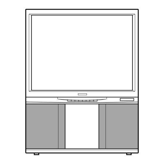
- Page 1 COLOR TV SERVICE MANUAL CHASSIS : MP-55A MODEL : PF-43A10 CAUTION BEFORE SERVICING THE CHASSIS, READ THE SAFETY PRECAUTIONS IN THIS MANUAL.
-
Page 2: Table Of Contents
CONTENTS Contents ...........................2 Safety Precautions......................3 I I . Servicing Precautions....................4 I I I . Specifications........................6 Control Descriptions....................8 Alignment/T est Point Location Guide ............12 VII. Adjustment Instructions ..................16 VIII. Circuit Descriptions ....................23 T rouble Shooting......................33 Printed Circuit Boards ....................39 Wiring Diagram ......................57 XII. -
Page 3: I I . Safety Precautions
SAFETY PRECAUTIONS IMPORT ANT SAFETY NOTICE Many electrical and mechanical parts in this chassis have special safety-related characteristics. These parts are identified by the Schematic Diagram and Replacement Parts List. It is essential that these special safety parts should be replaced with the same components as recommended in this manual to prevent X-RADIATION, Shock, Fire, or other Hazards. -
Page 4: Servicing Precautions
SERVICING PRECAUTIONS CAUTION: Before servicing receivers covered by this service transistors and semicounductor "chip" components. The manual and its supplements and addenda, read and follow the following techniques should be used to help reduce the SAFETY PRECAUTIONS on page 3 of this publication. incidence of component damage caused by static by static NOTE: If unforeseen circumstances create conflict between the electricity. - Page 5 c. Qulckly move the soldering iron tip to the junction of the Fuse and Conventional Resistor component lead and the printed circuit foil, and hold it Removal/Replacement there only until the solder flows onto and around both the 1. Clip each fuse or resistor lead at top of the circuit board component lead and the foil.
-
Page 6: Specifications
SPECIFICATIONS NOTE : Specifications and others are subject to change without notice for improvement. ● Video input system: ● Power requirements : Multi 26 System 100-270 Vac, 50/60HZ (Refer to Table 1) ● Intermediate Frequency ● Power consumption : Vision IF : 38.0MHz 210 Wmax. - Page 7 T able 1 : Receiving System (26 System) Receiving System Receiving Channel Function P P A A L L - - B B P P A A L L - - G G V V H H F F B B a a n n d d P P A A L L - - I I PAL/SECAM-B : : 2 2 - - 1 1 2 2...
- Page 8 CONTROL LOCATIONS Front S-VIDEO JACK VIDEO (L)-AUDIO-(R) S-VIDEO AV 2 (MONO) AV 2 S-VIDEO VIDEO (L)-AUDIO-(R) Remote Control Sensor (MONO) STAND-BY TV/AV POWER MENU Name of button Descriptions TV/AV To select TV or AV mode. MENU To select a menu. To accept your selection or to display the current mode.
- Page 9 Rear Panel 75Ω AUDIO VIDEO S-VIDEO EXT SP (8Ω) MAIN POWER SPEAKER - 9 -...
- Page 10 1. POWER REMOCON switches the set on from stand-by or off to stand-by. 2. MUTE POWER MUTE switches the sound on or off. 3. UNIT selects single or double digit. TV/AV 4. NUMBER BUTTONS MENU switch the set on from stand-by or directly select a number. 5.
- Page 11 MENU REFERENCE INPUTOOOOOOOOOO:TV ¶O50OTREBLEOOOOOOOO CLOCKO SSET CHILDOLOCKOOOOO:OFF ‚100OCONTRASTOOOOOOOO ∞O50OBASSOOOOOOOO ONOOTIMEOSET SOUNDOSYSTEMOOO:BG¡5.5™ 'O50OBRIGHTOOOOOOOO ¢O0OBALANCEOOOOOOO OFFOTIMEOSET COLOROSYSTEMOOO:AUTO ·O50OCOLOROOOOOOOO OOFFOSURROUNDOOOOOOO AUTOOSSLEEP NOISEOREDUCTION:OFF ≥O60OSHARPNESSOOOOOOO OOFFFUBBOOOOO CONVERGENCE OOOOOO ¡ ™OTOOSELECT ¡ ™OTOOSELECT ¡ ™™ TOOCHANGE ¡ OK™ OOTOOSET ¡ OK MENU™ ¡ OK MENU™ MENU 1 MENU 2 MENU 3 MENU 4...
-
Page 12: Alignment/Test Point Location Guide
ALIGNMENT/TEST POINT LOCATION GUIDE SIGNAL Board (Component side) P600 IC601 P604RB P601 IC603 MSW601 P604LB RF501 IC605 P04AP P900AP IC604 P800BP IC600 IC700 P902AP P103A P102A P101A P02AP IC501 IC500 TUNER P901AP IC200 P03AP P400AP IC1011 IC204 TP01A P401AP P502AP P756AP P01AP R801BP... - Page 13 CONVERGENCE & CRT(R, G, B) Board (Component Side) SCREEN B SCREEN G G DRIVE SCREEN R R DRIVE VR928G VR928R VR900B VR900G VR900R SIZE SKEW KEYS S-SKEW S-BOW M.LIN.S M.LIN.L M.WAVE WAVE-A WAVE-U VR1101 VR1102 VR1113 VR1114 VR1115 VR1132 VR1133 VR1144 VR1152 VR1153...
- Page 14 PIP Board (Component Side) IF Board (Component Side) - 14 -...
- Page 15 SCART/POW-SW Board (Component Side) P901 MSW801 P901BP P902BP IC901 P900BP TXTBoard (Component Side) TI02 TI 01 TI 04 TI 05 TP01 - 15 -...
-
Page 16: Adjustment Instructions
ADJUSTMENT INSTRUCTIONS Safety Precautions To TP2/ TP21 1. It is safe to adjust after using insulating transformer DC POWER 3.3K SUPPLY between the power supply line and chassis input to prevent 12 0.1V To TP5/ TP24 the risk of electric shock and protect the instrument. 2. - Page 17 ● Vertical/Horizontal Size Adjustment A: 36.8MHz Test Point : Observing Display B: 38.0MHz Adjust : VR301 (Vertical Size) VR404 (Horizontal Size) 1) Tune the TV set to receive a digital pattern. 2) Set contrast to 100%, brightness and color to 50% respectively.
- Page 18 2) Tune the TV set to receive white pattern of PAL SUB BRIGHT/COLOR/TINT adjustment standard signal. 3) Press OK button on Control Board continuously and NOTE : This adjustment should be performed after White INPUT(blue) button on remote controller for obtaining a Balance adjustment.
- Page 19 RASTER SLANT/POSITION, FOCUS & CONVERGENCE ADJUSTMENT Caution : ●Lens and Electrical Focus Adjustment These adjustments have been factory aligned. Do not attempt 1. Preliminary steps to temper with these alignments. However, the effects of 1) The electrical focus, the raster slant and position must be adjacent receiver components, or replacement of picture tube provisional alignment.
- Page 20 6) Adjust H-BOW volume VR1127. 4. Blue lens Adjustment 1) Turn the lens until the chromatic aberration changed purple to green which of 3.5 Cross-Hatch part from picture's center toward left. 2) Adjust the chromatic aberration become center of purple and green.
- Page 21 12) Adjust V-LIN. volume VR1104. 6) Adjust H-KEYSTONE volume VT1129(red)/VR1123(blue). ※ Adjust VR1143(red)/VR1139(blue) and VR1129(red)/ VR1123(blue) together for delicate alignment. 13) Adjust H-LIN. volume VR1110. 7) Adjust H-PINCUSHION volume VR1142(red)/VR1138(blue). ※ Adjust VR1150(red)/VR1147(blue) and VR1142(red)/ VR1138(blue) together for delicate alignment. If the picture is distorted after this adjustment, adjust 14) Adjust V-SIZE volume (VR301) and H-SIZE volume VR1151(red) and VR1148(blue) and readjust VR1150(red)/...
- Page 22 11) Adjust V-WAVE.A volume VR1169 (red)/VR1165 (blue). ※ Adjust VR1173 (red)/VR1171 (blue) and VR1169 (red)/ VR1165 (blue) together for delicate alignment. 12) Adjust V-LIN. volume VR1106 (red)/VR1102 (blue). 13) Adjust V-KEY volume VR1120 (red)/VR1114 (blue). ※ Adjust VR1137 (red)/VR1133 (blue) and VR1120 (red)/ VR1114 (blue) together for delicate alignment.
-
Page 23: Circuit Descriptions
CIRCUIT DESCRIPTIONS 1. µ-COM 4) Timer/Clock function 1-1. Function summary • Real Clock • On Time/OFF Time 1) Tuning function • Auto Sleep/Sleep Timer • Auto Program • Manual Search 5) Receiving System • Fine Tuning Memory • Full Mult : PAL/SECAM-BG/DK/I •... - Page 24 1-3 Control system Monitor CXA1545AS AV1 (S-AV) Tuner(Main) VIF/SIF AV2 (S-AV) AV3 (SCART) TV out (Scart) Tuner(Sub) Clock Data Chroma 3-Wire AFT - in Processor (TDA9160A) E PROM Processor (SDA9188-3X) RGB S/W AN5860 Y & C Switching MC144111P 3-Wire 1.TXT RGB 2.PIP (DAC) F .
- Page 25 2. SMPS POWER IC (STR-S6709) 2-1 Outline The STR-S6700 series is a Hybrid IC with a built-in power small number of external components, and simplifies transistor and a separate excitation control IC, designed for circuits design. It is very suitable for downsizing and converter type switch mode power supply applications.
- Page 26 2-5 pins Function and Description 1) Vin terminal (9 PIN), start circuit The start circuit perform the operation start and stop of control IC by voltage of VIN terminal (9 PIN). In power is start, if the Vin terminal voltage reaches to 8V(TYP) by charged in C6(A) through the start resistor, the control circuit operates and voltage generates to each of the trans wire wound.
- Page 27 4) DRIVE Circuit • BASE DRIVE current (IB1) and Sink current (IB2) control terminal for starting POWER TRANSISTOR. • COMPARISON DRIVE mode for reduce the switching DRIVE DRIVE Loss of POWER TRANSISTOR. (POWER 5) OCP Function (Protective Function Against Over Current) SINK This function is operated in the pulse by pulse way by...
- Page 28 3. Horizontal/Vertical Deflection 3-1 Horizontal Drive circuit 1) Summary Horizontal drive circuit connected between horizontal buffer amplifier to maintain the frequency of horizontal deflection output and horizontal oscillation circuit supplies base oscillation circuit from the effect of horizontal output circuit. current to operate horizontal output transistor and does as 2) Circuit Diagram Q422...
- Page 29 3-2. Basic operation of horizontal output circuit i1 (t1-t2) Q422 Primary winding of FBT H-DY t t t 2 3 4 of Q422 : Q422 is switched on. Collector Current of Q422 t1-t2 : Collector current of Q422 rise linearly. i1 flows from CS which have been left charged at the end of first half of scan.
- Page 30 3-3. Horizontal output circuit (Diode Modulation) 1) Summary 3) Description The horizontal deflection output circuit provides Diode The modulation of the horizontal deflection current at a Modulator funciotn which is for E-W Correction. vertical rate is accomplished in the following manner. During the first part of the scanning period, diodes Di1 and Di are 2) Circuit Diagram functioning as energy recovery diodes for the energy stored...
- Page 31 2) Basic Vertical drive Operation DY INPUT VOLTAGE IC301 DY INPUT CURRENT V-DY ● The first half of the scanning time turns on Q3(Q4 turns off) PIN2 of IC301 Collector of Q3 Emitter of Q3 V-DY Charge Cv by current i1 ●...
- Page 32 3-5. Projection TV and convergence 3-6. Necessity of Dynamic Focus The projection TV is CRT which generates one color light The CRT panel which used in PJTV is flat completely. So, of R.G.B and improved arrange lens Assy to in-line and the beam distance which scan to each corner and scan to appear screen by set screen to the lens focus's appearing center from Dy center are very different.
-
Page 33: Trouble Shooting
TROUBLE SHOOTING 1. NO RASTER Check+B voltage at C892 Normal Open Is the voltage at Pin5 Check F801A of IC501 9.1V? Check/Replace F801A, D821, Check the voltage D809~812, IC801, 5V, 9V, 12V line IC821 Does the square Check the voltage waveform from pin6 of of C808, C809 IC501 appear? - Page 34 3. NO PICTURE/NO SOUND (RASTER OK) Does the Auto search operation? Is the CVBS signal of pin3 Check the voltage of P102A normal? 33V, 5V or Tuner Check/Repalce Check IF Board ZD101, ZD103, R112, R118 GO TO Check the NO PICTURE Block pin3, 16, 10, 11, 13 fo IC1 NO SOUND Block 4.
- Page 35 5. NO SOUND (PICTURE OK) Check switch MSW601 position EXT. Check Sound system Set MSW601 to EXT of MENU OSD 5.5/6.0/6.5 Is the voltage of pin40 Is the voltage of of IC15V(High)? Pin40 of IC1 0V(Low)? Is the SIF signal of Pin22 of IC1T normal? Check/Replace IC1T...
- Page 36 6. NO PIP In case of Main/AV PIP In case of sub PIP Is the video signal of Is the CVBS signal of pin29 of IC600? pin24 of IC2P? Check/Replace IC600 Check TUNER/IF Check I C Bus parts of PIP Board Is the video signal of pin26 of IC2P Check P2A, P2B...
- Page 37 7. NO TELETEXT Check the voltage 12V at pin13 of TP01 Abnormal Normal Check the 12V line Check the voltage Abnormal to be correct of TC06 4.8~5.2V Check/Replace TI04 Check whether video signal is in at pin 3 of TI 01 or not Check whether video signal is in at the pin40 of IC600 or not Check I...
- Page 38 8. INCORRECT CONVERGENCE Does the static convergence correct? INCORRECT Dynamic INCORRECT Static Check the connector Readjust static convergence by P112BP, P113AP, P115B remote controller. on the convergence PCB Not Controlled Controlled Check Hp, Vp signal of Does the voltage of pin2,4,9,11 of pin24, 5 of IC1101 IC1011 on the signal PCB change as adjusting static convergence?
- Page 39 8. INCORRECT CONVERGENCE Does the static convergence correct? INCORRECT Static INCORRECT Dynamic Check the connector Readjust static convergence by P112BP, P113AP, P115B remote controller. on the convergence PCB Not Controlled Controlled Check Hp, Vp signal of Does the voltage of pin2,4,9,11 of pin24, 5 of IC1101 IC1011 on the signal PCB change as adjusting static convergence?
- Page 40 C303 ....E3 C2005 ..E2 E3 ....A1 G29....A4 J103 ....G2 R302 ....E4 R451 ...G5 R2040 ..A2 C304 ....E3 C2006 ..E2 E4 ....B1 G30....A4 J104 ....G3 R303 ....F3 R452 ...G5 R2044 ..F1 C307 ....E3 C2007 ..E2 E5 ....C1 G31 .....D4 J105.....E3 R304 ....F3 R453 ...G5 R2045 ..F1 C309 ....E3...
- Page 41 AR1....C1 C507 ....E2 C577 ....G3 C667....F5 IC2 .....A1 J68 .....C3 J139 ....F2 C1 ......D3 C508 ....E2 C578 ....G2 C668....F4 IC3 .....C1 J69 .....B1 J140 ....B1 C2 ......C3 C509 ....E2 C579 ....G2 C669....F5 IC200 ....E2 J71 .....C3 J142 ....C1 C3 ......C3 C510 ....E2 C580 ....G2 C700 ....D5...
- Page 42 J212....G4 L506....G2 Q707 ....E5 R85 ....C3 R530....F2 R668 ....D4 R741 ....D4 J213 ....B3 L600 ....B4 Q708 ....D3 R87 ....C3 R531 ....G2 R669 ....D4 R742 ....D2 J214 ....B2 L601....D4 Q709 ....E5 R88 ....C3 R532 ....E3 R670 ....C4 R743 ....D4 J215 ....B2 L602....D4 R2 ......A1 R89 ....C3...
- Page 43 C1100.....B5 C1163 ....G4 IC1103....E4 J52......F5 J120 .......C4 J195......E5 C1101.....B4 C1164 ....G4 IC1104 ....G5 J53......E5 J121 .......D4 J196 .......C4 C1102.....B5 C1165 ....G4 IC1105 ....F5 J54......F5 J122 .......G4 J197......E4 C1103.....B5 C1166 .....F4 IC1106 ....G4 J55......F5 J123 .......G4 J198......E4 C1104.....A5 C1167 ....G5 IC1107 ....F4 J56......F4 J124 .......G4 J199......A3...
- Page 44 R1127.....B2 R1190.....C3 R1257.....E4 R1318 ....G4 R932G....C1 VR1138 ....C4 R1128.....B3 R1192.....D3 R1258 ....G5 R1319 ....G4 R932R ....F1 VR1139 ....C4 R1129.....B3 R1193.....D4 R1259 ....G5 R1320.....E5 R933B ....B1 VR1140 ....C4 R1130.....B3 R1195.....B3 R1260 ....G5 R1321.....E3 R933G....D1 VR1141 ....C4 R1131.....B3 R1196.....B3 R1261 .....F5 R1322.....C4 R933R ....F1 VR1142 ....C4 R1132.....B4...
- Page 45 C351 ....G1 C874....B1 D861....A1 G7 ....E1 J863....F4 R357 ....G2 R845....F2 C352 ....G1 C875....F4 D862....B1 G8 ....E2 J864 ....G1 R358 ....G2 R846....F5 C353 ....G1 C876....F5 D863....A1 G9 ....E2 J865 ....E4 R359 ....G2 R848 ....D4 C354 ....G2 C877....F4 D866....F4 G10 ....D2 J866....F3 R360....F1 R849 ....D4 C355 ....G2...
-
Page 46: Printed Circuit Boards
PRINTED CIRCUIT BOARDS 1. SIGNAL (Component Side) 2. SMPS (Component Side) 3. DEFLECTION (Component Side) 4. CONVERGENCE & CRT (Component Side) 5. IF (Component Side) IF (Copper Side) 6. PIP (Component Side) PIP (Copper Side) 7. CONTROL (Component Side) 8. SCART/POW-SW (Component Side) 9. - Page 48 HOLDER, MIRROR(B) 341-772A LENS, ASSY,GSPL-5N(G) 392-105B MIRROR, FRONT SURFACE 391-005B LENS, ASSY, GSPL-5N(R) 392-105A HOLDER, MIRROR(C) 341-773A SUPPORTER, LENS/CRT PF-43A10 343-B56A TRUSS HEAD T D4 L20 1TTG0403316 DY, DY-V90-7ST, MZMD20 153-359A CASE, MIRROR 302-726A CAP, BALLON 304-113B TRUSS HEAD T D4.0 L16...
- Page 66 Apr., 1997 P/No.; 483-920C Printed in Korea...