Table of Contents
Advertisement
Available languages
Available languages
Quick Links
Advertisement
Table of Contents

Related Manuals for Axis Ex Series


Summary of Contents for Axis Ex Series
- Page 1 AXIS Ex Series Installation Manual IM001...
- Page 3 English Français Deutsch Italiano Español 日本語 中文: 简体中文...
-
Page 4: Version History
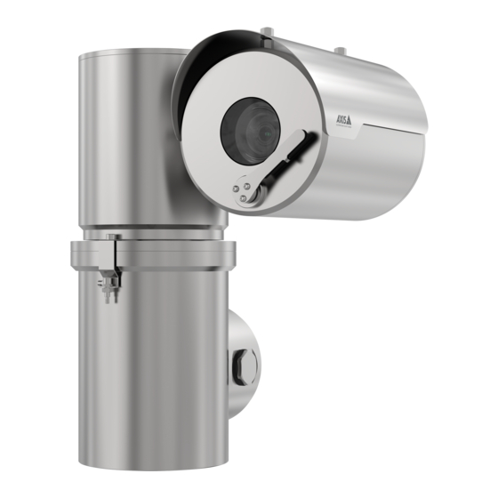
AXIS Ex Series Version history Version Date Details 2021-09-17 First release 2022-01-10 Added mining information... - Page 5 AXIS Ex Series Models The AXIS Ex camera series has four models: two types with PTZ housings and two types with fixed housings, each with visual imaging options and thermal imaging options. The visual cameras include a wiper. Type Housing Details ∅138 L210 housing...
-
Page 6: Specific Conditions Of Use
AXIS Ex Series Specific conditions of use WARNING Always refer to the product certificates for any specific conditions of use. • Flameproof joints are not to be modified. • Cable temperature can exceed 60 °C. Use a suitable cable for the end application. -
Page 7: Installation
All entries must be plugged with suitable certified equipment. Fixing brackets must be tightened upon installation. Suitable screws must be used. See the product’s datasheet for information about the product weight. Replacement parts may only be installed using component parts as specified by Axis Ex AB. - Page 8 AXIS Ex Series Wiring WARNING The device must be electrically installed and serviced by skilled persons. AC mains electrical supply should include circuit breaker rated maximum 20 A. The device requires a surge protector device, as part of the installation, to prevent transient overvoltage exceeding 2 500 Vpk.
- Page 9 AXIS Ex Series Wiring of P21 and P23 Earth supplemental bonding TB1 auxiliary OUT Network connector RJ45 SFP cage TB2 supply IN Earth stud TB2 supply live TB2 supply neutral TB2 N/C 10 TB1 auxiliary OUT +48 V DC 14.4 W max 11 TB1 auxiliary OUT 0 V DC Connect the PTZ camera wiring to the connection chamber at the base of the device.
- Page 10 AXIS Ex Series 1. Remove the two locking grub screws. Use the included stainless steel bits. 2. Remove the threaded chamber cover. To avoid damaging the threads, use the included removal tool. 3. Route the cables through threaded entry points and suitably certified glands.
- Page 11 AXIS Ex Series Wiring of F31 and F33 Earth supplemental bonding Earth stud TB2 supply IN TB1 auxiliary OUT SFP cage Network connector RJ45 TB2 supply live TB2 supply neutral TB2 N/C 10 TB1 auxiliary OUT +48 V DC 14.4 W max 11 TB1 auxiliary OUT 0 V DC Connect the fixed camera wiring to the connection terminal at the back of the device.
- Page 12 AXIS Ex Series 2. Remove the back cover. Carefully pull the back cover off. 3. Route the cables through threaded entry points and suitably certified glands. CAUTION Take extra care to not damage the joint surface. WARNING Earthing connection must be minimum 14 AWG (2 mm²) conductor with green and yellow insulation.
-
Page 13: Maintenance
AXIS Ex Series Maintenance The device does not contain any servicable parts. No covers or seals should be removed. WARNING It is strictly prohibited to carry out any attempt of repairs other than by approved and trained personnel. Check all mounting fasteners for tightness at a regular interval. -
Page 14: Specifications
AXIS Ex Series Specifications Markings You can find the markings on the devices’ main body. Note Information below is only an example. For specific information, see the product’s datasheet. Manufacturer’s name and address Axis Ex AB Gränden 1 SE-223 69 LUND... - Page 15 AXIS Ex Series Voltage PTZ: 100 - 240 V AC ±10% Fixed: 100 - 240 V AC ±10% POE 802.3bt Type 3 Power PTZ: 150 W Fixed: 56 W Frequency 50 - 60 Hz Entry thread size M25 or M20 depending on model...
- Page 16 AXIS Ex Series Dimensions type P21 and P23...
- Page 17 AXIS Ex Series Dimensions type F31 and F33...
-
Page 18: Further Information
Further information • The user manual is available at axis.com • To check if there is updated firmware available for your device, see axis.com/support • For useful online trainings and webinars, see axis.com/academy Optional accessories For a complete list of available accessories for this product, go to the product’s page on axis.com and select Software &... -
Page 19: Safety Information
AXIS Ex Series Safety information Hazard levels DANGER Indicates a hazardous situation which, if not avoided, will result in death or serious injury. WARNING Indicates a hazardous situation which, if not avoided, could result in death or serious injury. CAUTION Indicates a hazardous situation which, if not avoided, could result in minor or moderate injury. - Page 20 AXIS Ex Series Historique de la version Version Date Détails 2021-09-17 Première version 2022-01-10 Informations minières ajoutées...
- Page 21 AXIS Ex Series Modèles La série de caméras AXIS Ex comporte 4 modèles : 2 modèles avec boîtier PTZ et 2 modèles avec boîtier fixe, chacun avec options d'imagerie visuelle et options d'imagerie thermique. Les caméras visuelles intègrent un essuie-glace.
- Page 22 AXIS Ex Series Conditions d'utilisation spécifiques AVERTISSEMENT Pour toute condition d'utilisation spécifique, consultez les certificats du produit. • Les joints ignifuges ne doivent pas être modifiés. • La température du câble peut dépasser 60 °C. Utilisez un câble adapté à l'application finale.
-
Page 23: Installation
AXIS Ex Series Installation AVERTISSEMENT Toute installation et opération de maintenance doit être réalisée par un électricien qualifié conformément à toutes les normes et codes de pratique locaux et nationaux : p. ex. NFPA70 (Code électrique national), CSA C22.1 (Code canadien de l'électricité, Norme de sécurité... - Page 24 AXIS Ex Series Les pièces de rechange ne peuvent être montées qu'à l'aide de composants, comme spécifié par Axis Ex AB. Câblage AVERTISSEMENT L'installation électrique et l'entretien du périphérique doivent être réalisés par des personnes qualifiées. L'alimentation électrique sur secteur doit inclure un disjoncteur de 20 A maximum.
- Page 25 AXIS Ex Series Câblage des P21 et P23 Liaison supplémentaire à la terre SORTIE auxiliaire TB1 Connecteur réseau RJ45 Cage SFP ENTRÉE alimentation TB2 Goujon de mise à la terre Alimentation TB2 en direct Alimentation TB2 neutre N.C. TB2 10 SORTIE auxiliaire TB1 +48 V CC 14.4 W max.
- Page 26 AXIS Ex Series 1. Retirez les 2 vis sans tête verrouillées. Utilisez les parties inox incluses. 2. Retirez le couvercle de la chambre filetée. Pour éviter d'endommager les filetages, utilisez l'outil de retrait inclus. 3. Passez les câbles à travers les points d'entrée filetés et les presse-étoupe certifiés.
- Page 27 AXIS Ex Series Câblage des F31 et F33 Liaison supplémentaire à la terre Goujon de mise à la terre ENTRÉE alimentation TB2 SORTIE auxiliaire TB1 Cage SFP Connecteur réseau RJ45 Alimentation TB2 en direct Alimentation TB2 neutre N.C. TB2 10 SORTIE auxiliaire TB1 +48 V CC 14.4 W max.
- Page 28 AXIS Ex Series 2. Retirez le panneau arrière. Enlevez soigneusement le couvercle arrière. 3. Passez les câbles à travers les points d'entrée filetés et les presse-étoupe certifiés. ATTENTION Faites très attention à ne pas endommager la surface du joint. AVERTISSEMENT Le branchement à...
- Page 29 AXIS Ex Series Maintenance Le périphérique ne contient aucune partie réparable. Aucun couvercle ni joint ne doit être retiré. AVERTISSEMENT Il est strictement interdit de réaliser toute tentative de réparation autre que par du personnel agréé et formé. Vérifiez régulièrement l'étanchéité de tous les éléments de fixation.
-
Page 30: Caractéristiques Techniques
AXIS Ex Series Caractéristiques techniques Marques Les marques se trouvent sur le corps principal des périphériques. Remarque Les informations ci-dessous sont données à titre d'exemple. Pour des informations précises, consultez la fiche technique du produit. Nom et adresse du fabricant Axis Ex AB Gränden 1... - Page 31 AXIS Ex Series Tension PTZ : 100 à 240 V CA ±10 % Fixe : 100 à 240 V CA ±10 % POE 802.3bt de type 3 Alimentation PTZ : 150 W Fixe : 56 W Fréquence 50 à 60 Hz Taille du filetage en entrée...
- Page 32 AXIS Ex Series Type de dimensions P21 et P23...
- Page 33 AXIS Ex Series Type de dimensions F31 et F33...
-
Page 34: Informations Supplémentaires
• Le manuel d'utilisation est disponible sur axis.com • Pour vérifier si le firmware a été mis à jour pour votre périphérique, voir axis.com/support • Pour accéder à des formations et webinaires en ligne utiles, voir axis.com/academy Accessoires en option Pour une liste complète des accessoires disponibles pour ce produit, accédez à... -
Page 35: Informations Sur La Sécurité
AXIS Ex Series Informations sur la sécurité Niveaux de risques DANGER Indique une situation dangereuse qui, si elle n'est pas évitée, entraînera le décès ou des blessures graves. AVERTISSEMENT Indique une situation dangereuse qui, si elle n'est pas évitée, pourrait entraîner le décès ou des blessures graves. - Page 36 AXIS Ex Series Versionsverlauf Version Datum Details 2021-09-17 Erste Version 2022-01-10 Zusätzliche Informationen zum Bergbau...
- Page 37 AXIS Ex Series Modelle Die AXIS Ex-Kameraserie umfasst vier Modelle: Zwei Typen mit PTZ-Gehäuse und zwei Typen mit festem Gehäuse, jeweils mit Optionen für visuelle Bilder und Wärmebilder. Die visuellen Kameras sind mit einem Wischer ausgestattet. Gehäuse Details ∅138 L210 Gehäuse Wischer ∅138 L210 Gehäuse...
- Page 38 AXIS Ex Series Besondere Verwendungsbedingungen WARNUNG Die besonderen Verwendungsbedingungen sind stets den Produktzertifikaten zu entnehmen. • Flammensichere Verbindungen dürfen nicht verändert werden. • Die Kabeltemperatur kann 60 °C überschreiten. Verwenden Sie ein für die Endanwendung geeignetes Kabel. • Für die Kabeleinführung in das Gerät sind entsprechend zertifizierte Kabelverschraubungen, Gewindeadapter oder Stecker zu verwenden, die einen Mindestschutz bieten, um die Schutzklasse des Geräts zu erhalten.
- Page 39 AXIS Ex Series Installation WARNUNG Alle Installations- und Wartungsarbeiten müssen von einer entsprechend ausgebildeten Elektrofachkraft in Übereinstimmung mit allen lokalen und nationalen Normen und Vorschriften durchgeführt werden, z. B. NFPA70 (National Electrical Code), CSA C22.1 (Canadian Electrical Code, Part I Safety Standard for Electrical Installations), IEC/EN 60079-14 (Explosive Atmosphären –...
- Page 40 AXIS Ex Series Für den Einbau von Ersatzteilen dürfen nur die von Axis Ex AB angegebenen Komponenten verwendet werden. Verkabelung WARNUNG Das Gerät muss von Fachleuten elektrisch installiert und gewartet werden. Die Netzstromversorgung sollte einen Schutzschalter mit einer maximalen Stromstärke von 20 A enthalten.
- Page 41 AXIS Ex Series Verdrahtung von P21 und P23 Zusätzlicher Erdungsanschluss TB1-Hilfsausgang OUT Netzwerk-Anschluss RJ45 SFP-Käfig TB2-Versorgung IN Erdungsbolzen TB2-Versorgung live TB2-Versorgung neutral TB2 N/C 10 TB1-Hilfsausgang OUT +48 V DC, max. 14.4 W max 11 TB1-Hilfsausgang OUT 0 V DC...
- Page 42 AXIS Ex Series 1. Entfernen Sie die beiden Sicherungsgewindestifte. Verwenden Sie die mitgelieferten Bits aus rostfreiem Stahl. 2. Entfernen Sie den Gewindekammerdeckel. Verwenden Sie das mitgelieferte Abziehwerkzeug, um die Gewinde nicht zu beschädigen. 3. Führen Sie die Kabel durch Gewindeeinführungen und entsprechend zertifizierte Verschraubungen.
- Page 43 AXIS Ex Series Verdrahtung von F31 und F33 Zusätzlicher Erdungsanschluss Erdungsbolzen TB2-Versorgung IN TB1-Hilfsausgang OUT SFP-Käfig Netzwerk-Anschluss RJ45 TB2-Versorgung live TB2-Versorgung neutral TB2 N/C 10 TB1-Hilfsausgang OUT +48 V DC, max. 14.4 W max 11 TB1-Hilfsausgang OUT 0 V DC Schließen Sie das Kabel der fest installierten Kamera an die Anschlussklemme auf der Rückseite des...
- Page 44 AXIS Ex Series 1. Entfernen Sie die 6 M5x12 A4-Innensechskantschrauben. Verwenden Sie die mitgelieferten Bits aus rostfreiem Stahl. 2. Entfernen Sie die hintere Abdeckung. Ziehen Sie die hintere Abdeckung vorsichtig ab. 3. Führen Sie die Kabel durch Gewindeeinführungen und entsprechend zertifizierte Verschraubungen.
-
Page 45: Wartung
AXIS Ex Series Wartung Das Gerät enthält keine zu wartenden Teile. Es dürfen keine Abdeckungen oder Abdichtungen entfernt werden. WARNUNG Es ist strengstens untersagt, Reparaturversuche durchzuführen, die nicht von zugelassenem und geschultem Personal ausgeführt werden. Überprüfen Sie regelmäßig alle Befestigungselemente auf festen Sitz. -
Page 46: Technische Daten
AXIS Ex Series Technische Daten Kennzeichnungen Die Kennzeichnungen finden Sie auf dem Gehäuse des Geräts. Hinweis Die folgenden Informationen sind nur ein Beispiel. Spezifische Informationen finden Sie im Datenblatt des Produkts. Name und Adresse des Herstellers Axis Ex AB Gränden 1... - Page 47 AXIS Ex Series Spannung PTZ: 100–240 V AC ± 10 % Fest: 100–240 V AC ± 10 % POE 802.3bt Typ 3 Leistung PTZ: 150 W Fest: 56 W Frequenz 50–60 Hz Größe des Eingangsgewindes M25 oder M20, je nach Modell...
- Page 48 AXIS Ex Series Abmessungen Typ P21 und P23...
- Page 49 AXIS Ex Series Abmessungen Typ F31 und F33...
-
Page 50: Weitere Informationen
Unter axis.com/support finden Sie die aktuellen Firmwareversionen für Ihr Gerät. • Nützliches Onlinetraining und Webinare finden Sie unter axis.com/academy. Optionales Zubehör Eine vollständige Liste lieferbaren Zubehörs für dieses Produkt finden Sie auf axis.com unter Produkt, Software und Zubehör. Kontaktinformationen Axis Ex AB Gränden 1... -
Page 51: Andere Meldeebenen
AXIS Ex Series Sicherheitsinformationen Gefährdungsstufen GEFAHR Weist auf eine gefährliche Situation hin, welche, falls nicht verhindert, zu Tod oder schweren Verletzungen führen kann. WARNUNG Weist auf eine gefährliche Situation hin, welche, falls nicht verhindert, zu Tod oder schweren Verletzungen führen kann. - Page 52 AXIS Ex Series Cronologia delle versioni Versione Data Dettagli 2021-09-17 Prima release 2022-01-10 Informazioni aggiuntive in merito al settore minerario...
- Page 53 AXIS Ex Series Modelli L'AXIS Ex camera series comprende quattro modelli: due dotati di alloggiamento PTZ e due di alloggiamenti fissi, ognuno con possibilità di acquisizione di immagini visive e possibilità di acquisizione di immagini termiche. Nelle telecamere visive è compreso un tergicristallo.
- Page 54 AXIS Ex Series Condizioni d'uso specifiche AVVISO Per qualsiasi condizione d'uso specifica, si devono sempre consultare i certificati del dispositivo. • Non si devono modificare i giunti ignifughi. • Il cavo può raggiungere temperature superiori ai 60 °C. Impiegare un cavo idoneo per l'applicazione finale.
-
Page 55: Installazione
AXIS Ex Series Installazione AVVISO Ogni operazione di installazione e manutenzione va eseguita da un elettricista adeguatamente qualificato conformemente a tutti gli standard e i codici di buona prassi locali e nazionali, ad es. NFPA70 (National Electrical Code), CSA C22.1 (Canadian Electrical... - Page 56 AXIS Ex Series Le staffe di fissaggio devono essere serrate al momento dell'installazione. È importante utilizzare viti idonee. Per informazioni sul peso del prodotto, consultare la scheda tecnica del prodotto. Si possono installare pezzi di ricambio unicamente tramite l'uso di componenti specificati da Axis Ex AB.
- Page 57 AXIS Ex Series Cablaggio di P21 e P23 Collegamento a terra supplementare USCITA ausiliaria TB1 Connettore di rete RJ45 Gabbia SFP INGRESSO alimentazione TB2 Perno di messa a terra Alimentazione attiva TB2 Neutro di alimentazione TB2 N/C TB2 10 USCITA ausiliaria TB1 +48 V CC 14.4 W max...
- Page 58 AXIS Ex Series Eseguire la connessione del cablaggio della telecamera PTZ alla camera di collegamento alla base del dispositivo. 1. Rimuovere le due viti di fermo per il blocco. Impiegare le punte in acciaio inossidabile in dotazione. 2. Rimuovere il coperchio della camera filettata. Per fare in modo di non causare danni alle filettature, impiegare lo strumento di rimozione in dotazione.
- Page 59 AXIS Ex Series Cablaggio di F31 e F33 Collegamento a terra supplementare Perno di messa a terra INGRESSO alimentazione TB2 USCITA ausiliaria TB1 Gabbia SFP Connettore di rete RJ45 Alimentazione attiva TB2 Neutro di alimentazione TB2 N/C TB2 10 USCITA ausiliaria TB1 +48 V CC 14.4 W max 11 USCITA ausiliaria TB1 0 V CC Connettere il cablaggio della telecamera fissa al terminale di connessione sul retro del dispositivo.
- Page 60 AXIS Ex Series 1. Rimuovere le 6 viti a brugola M5x12 A4. Impiegare le punte in acciaio inossidabile in dotazione. 2. Rimuovere il coperchio posteriore. Staccare delicatamente il coperchio posteriore. 3. Instradare i cavi tramite punti di ingresso filettati e passacavi dotati di certificazione idonea.
-
Page 61: Manutenzione
AXIS Ex Series Manutenzione In questo dispositivo non sono presenti componenti riparabili dall'utente. Non si devono rimuovere né coperchi né guarnizioni. AVVISO Qualsiasi tentativo di riparazione che non sia effettuato da personale autorizzato e addestrato è severamente proibito. La tenuta di ogni fissaggio di montaggio deve essere controllata a intervalli regolari. -
Page 62: Dati Tecnici
AXIS Ex Series Dati tecnici Marcature Si possono trovare le marcature sul corpo principale del dispositivo. Nota Le informazioni di cui sotto rappresentano solo un esempio. Consultare la scheda tecnica del dispositivo per ottenere informazioni specifiche. Nome e indirizzo del produttore Axis Ex AB Gränden 1... - Page 63 AXIS Ex Series Tensione PTZ: 100 - 240 V CA ±10% Fissa: 100 - 240 V CA ±10% POE 802.3bt Tipo 3 Alimentazione PTZ: 150 W Fissa: 56 W Frequenza 50 - 60 Hz Dimensione filettatura ingresso M25 o M20, a seconda del modello...
- Page 64 AXIS Ex Series Tipo di dimensioni P21 e P23...
- Page 65 AXIS Ex Series Tipo di dimensioni F31 e F33...
-
Page 66: Ulteriori Informazioni
Per verificare se sono stati pubblicati aggiornamenti del firmware per il proprio dispositivo, vedere axis.com/support • Per servizi di formazione utili e webinar, visita il sito axis.com/academy Accessori opzionali Per un elenco completo degli accessori disponibili per questo dispositivo, andare alla pagina del dispositivo al sito axis.com e selezionare Software e accessori. -
Page 67: Informazioni Di Sicurezza
AXIS Ex Series Informazioni di sicurezza Livelli di pericolo PERICOLO Indica una situazione pericolosa che, se non evitata, provoca morte o lesioni gravi. AVVISO Indica una situazione pericolosa che, se non evitata, potrebbe provocare la morte o lesioni gravi. ATTENZIONE Indica una situazione pericolosa che, se non evitata, potrebbe provocare lesioni medie o minori. - Page 68 AXIS Ex Series Historial de versiones Fecha Detalles Versión 2021-09-17 Primera versión 2022-01-10 Se añadió la información sobre minería.
- Page 69 AXIS Ex Series Modelos La serie de cámaras AXIS Ex consta de cuatro modelos: dos tipos con carcasas PTZ y dos tipos con carcasas fijas. Todos tienen opciones de creación de imágenes visuales y de imágenes térmicas. Las cámaras visuales tienen una escobilla limpiadora.
- Page 70 AXIS Ex Series Condiciones de uso específicas ADVERTENCIA Consulte siempre los certificados de los productos para obtener información sobre las condiciones de uso específicas. • Las juntas ignífugas no se deben modificar. • La temperatura del cable puede superar los 60 °C. Use un cable adecuado para el uso final.
-
Page 71: Instalación
AXIS Ex Series Instalación ADVERTENCIA La instalación y el mantenimiento deben ser realizados por un electricista con la cualificación adecuada, y de conformidad con todas las normas y códigos de prácticas locales y nacionales. Por ejemplo, NFPA70 (Código eléctrico nacional), CSA C22.1 (Código eléctrico canadiense, estándar de seguridad de la Parte I para instalaciones eléctricas),... - Page 72 AXIS Ex Series Las piezas de repuesto solo pueden montarse utilizando las piezas de componentes especificadas por Axis Ex AB. Cableado ADVERTENCIA La instalación eléctrica y el mantenimiento del dispositivo solo deben llevarse a cabo por personas cualificadas. La fuente de alimentación de CA debe incluir un disyuntor de 20 A como máximo.
- Page 73 AXIS Ex Series Cableado de los tipos P21 y P23 Conexión a tierra complementaria Salida auxiliar TB1 Conector de red RJ45 Jaula SFP Entrada de alimentación TB2 Perno de conexión a tierra Alimentación activa TB2 Alimentación neutra TB2 TB2 N/C 10 SALIDA auxiliar TB1 +48 V CC 14.4 W máx.
- Page 74 AXIS Ex Series 1. Extraiga los dos tornillos de bloqueo sin cabeza. Utilice las brocas de acero inoxidable incluidas. 2. Retire la cubierta de la cámara roscada. Para no dañar la rosca, use la herramienta de extracción suministrada. 3. Pase los cables por los puntos de entrada con rosca y los prensaestopas con la certificación correcta.
- Page 75 AXIS Ex Series Cableado de los tipos F31 y F33 Conexión a tierra complementaria Perno de conexión a tierra Entrada de alimentación TB2 Salida auxiliar TB1 Jaula SFP Conector de red RJ45 Alimentación activa TB2 Alimentación neutra TB2 TB2 N/C 10 SALIDA auxiliar TB1 +48 V CC 14.4 W máx.
- Page 76 AXIS Ex Series 1. Extraiga los 6 tornillos M5x12 del cabezal del conector A4. Utilice las brocas de acero inoxidable incluidas. 2. Extraiga la cubierta trasera. Retire con cuidado la cubierta posterior. 3. Pase los cables por los puntos de entrada con rosca y los prensaestopas con la certificación correcta.
-
Page 77: Mantenimiento
AXIS Ex Series Mantenimiento El dispositivo no contiene piezas que se pueden reparar. No deben quitarse ni cubiertas ni juntas. ADVERTENCIA Está terminantemente prohibida la realización de cualquier intento de reparación por personal que no sea el aprobado y tenga la formación correspondiente. -
Page 78: Especificaciones
AXIS Ex Series Especificaciones Marcas Las marcas están en el cuerpo principal de los dispositivos. Nota La información siguiente es solo un ejemplo. Para obtener información específica, consulte la hoja de datos del producto. Nombre y dirección del fabricante Axis Ex AB Gränden 1... - Page 79 AXIS Ex Series Tensión PTZ: De 100 a 240 V CA ±10 % Fija: De 100 a 240 V CA ±10 % POE 802.3bt Tipo 3 Potencia PTZ: 150 W Fija: 56 W Frecuencia 50-60 Hz Tamaño de rosca de entrada...
- Page 80 AXIS Ex Series Dimensiones de los tipos P21 y P23...
- Page 81 AXIS Ex Series Dimensiones de los tipos F31 y F33...
-
Page 82: Más Información
AXIS Ex Series Más información • El manual de usuario se encuentra disponible en axis.com. • Para comprobar si existe un firmware actualizado disponible para su dispositivo, vaya a axis.com/support. • Para consultar webinars y cursos en línea que pueden resultarle útiles, vaya a axis.com/academy. -
Page 83: Información De Seguridad
AXIS Ex Series Información de seguridad Niveles de peligro PELIGRO Indica una situación peligrosa que, si no se evita, provocará lesiones graves o la muerte. ADVERTENCIA Indica una situación peligrosa que, si no se evita, puede provocar lesiones graves o la muerte. - Page 84 AXIS Ex Series バ バ バ ー ー ー ジ ジ ジ ョ ョ ョ ン ン ン 履 履 履 歴 歴 歴 ⽇ ⽇ ⽇ 付 付 付 詳 詳 詳 細 細 細 バ バ バ ー ー ー ジ ジ ジ ョ ョ ョ ン ン ン...
- Page 85 AXIS Ex Series モ モ モ デ デ デ ル ル ル AXIS Exカメラシリーズには、次の4つのモデルがあります。 PTZハウジング付きの 2タイプと固定ハウジング付き2タイプ。それぞれビジュアルイメージングオプ ションとサーマルイメージングオプションがあります。 ビジュアルカメラはワイ パーを付属しています。 詳 詳 詳 細 細 細 タ タ タ イ イ イ プ プ プ Housing Housing Housing ( ( ( ハ ハ ハ ウ ウ ウ ジ ジ ジ ン ン ン グ グ グ ) ) ) ワイパー...
- Page 86 AXIS Ex Series 具 具 具 体 体 体 的 的 的 な な な 使 使 使 ⽤ ⽤ ⽤ 条 条 条 件 件 件 警告 具体的な使⽤条件については、必ず製品証明書を参照してください。 防炎構造の接合部は変更しないでください。 • ケーブル温度は60 °Cを超える場合があります。 最終⽤途に適したケー • ブルを使⽤してください。 機器のケーブル⼊り⼝には、適切に認証されたケーブルグランド、ネジア • ダプター、またはプラグを使⽤する必要があり、これらは機器の浸⼊等級 を維持するために最低限の保護を提供する必要があります。 最低でもIP66 またはIP67である必要があります。...
- Page 87 AXIS Ex Series 設 設 設 置 置 置 警告 すべての設置とメンテナンスは、次に⽰すすべての地域および国の規格と実 施規範に従って、適切な技術を持った電気技師が⾏わなければなりません。 NFPA70 (⽶国電気⼯事規定)、CSA C22.1 (カナダ電気⼯事規定、第1部電気設備 に関する安全規格)、IEC/EN 60079-14 (爆発性雰囲気 - 電気設備の設計、選択、 建設)、IEC/EN 60079-17 (爆発性雰囲気、電気設備の検査とメンテナンス)。 設置者は、添付の技術データに準拠している必要があります。 すべての品⽬が環境および設置条件に対して承認され、認定されているこ とを確認してください。 本ユニットが適切な周囲温度と環境条件で使⽤さ れていること、および電源が適切であることを、定格ラベルで確認する必 要があります。 さび汚れや孔⾷を防ぐために、ステンレス製の⼯具を使⽤してください。 ス テンレススチールには耐腐⾷性がありますが、材質の取り扱いを誤ると、 外側がさびる可能性があります。 機器は海抜2,000m以下に設置する必要があります。 装置の改造や設計変更は許可されません。 安全規則と国の規制を遵守する必要があります。 周囲温度の範囲を超える可能性のある場所には、絶対に装置を設置しな いでください。 刺激の強い物質は、追加の保護が必要な場合があります。...
- Page 88 AXIS Ex Series 交換部品は、Axis Ex AB指定のコンポーネント部品のみを使⽤して取り付け ることができます。 配 配 配 線 線 線 警告 本装置の電気的な設置や修理は、熟練した⼈が⾏ってください。 AC主電源には最⼤20 Aのサーキットブレーカーが必要です。 本装置には、2,500 Vpkを超える過渡過電圧を防ぐために、サージ保護器も 併せて設置する必要があります。 AC主電源には、容易にアクセスできる全 極主電源断路装置が、建物設備の⼀部として提供されている必要がありま す。本装置は、内部アース端⼦への接続により保護アースに接続されてい る必要があります。 外部アースポイントは、現地当局がそのような接続を許可または要求する場 合にのみ、補完ボンディング⽤です。 アース接続フェルールは、腐⾷を避けるために適切な材質である必要が あります。 操作を開始する前に、本装置を電源から切り離します。 メンテナンスや接続を開始する前に、電圧が正しいことを確認してください。 適切に⾊分けされた導体またはその他の識別⼿段を使⽤してください。 アース導体は緑⾊と⻩⾊である必要があります。 ネジ⼭の形状を傷めないように⼗分注意してください。...
- Page 89 AXIS Ex Series P21 お お お よ よ よ び び び P23 P23 の の の 配 配 配 線 線 線 アース補完ボンディング TB1補助出⼒ ネットワークコネクターRJ45 SFPケージ TB2電源⼊⼒ アーススタッド TB2電源ライブ TB2電源ニュートラル TB2 N/C 10 TB1補助出⼒+48 V DC 14.4 W (最⼤) 11 TB1補助出⼒0 V DC...
- Page 90 AXIS Ex Series 1. 固定⽌めネジ2本を取り外します。 付属のステンレススチール製ビット を使⽤します。 2. ネジ式チャンバーカバーを取り外します。 ネジ⼭を傷つけないよう、付属 の取り外し⼯具を使⽤してください。 3. ネジ式⼊り⼝ポイントと適切に認定されたグランドにケーブルを通します。 警告 アース接続には、緑⾊と⻩⾊の絶縁体を持つ最⼩14 AWG (2 mm²) の導体を 使⽤する必要があります。 付属の圧着リングターミナルを使って、M4アー ススタッドを介して接続します。 7 mmのリングスパナまたはソケットで 締め付けます。 ターミナルプラグは、接続を解除して筐体の外側で簡単に終端処理することができ ます。 TB1およびTB2には、18〜12 AWG (0.8〜3.0 mm²) のワイヤーを使⽤します。 警告 各クランプポイントには1本のワイヤーのみを接続する必要があります。 外部アース接続ポイントは、11 AWG (4 mm²) までの接続に使⽤できます。 使⽤する...
- Page 91 AXIS Ex Series F31 お お お よ よ よ び び び F33 F33 の の の 配 配 配 線 線 線 アース補完ボンディング アーススタッド TB2電源⼊⼒ TB1補助出⼒ SFPケージ ネットワークコネクターRJ45 TB2電源ライブ TB2電源ニュートラル TB2 N/C 10 TB1補助出⼒+48 V DC 14.4 W (最⼤) 11 TB1補助出⼒0 V DC...
- Page 92 AXIS Ex Series 1. M5x12 A4ソケットヘッドネジ6本を取り外します。 付属のステンレスス チール製ビットを使⽤します。 2. バックカバーを取り外します。 慎重にバックカバーを引っ張って外します。 3. ネジ式⼊り⼝ポイントと適切に認定されたグランドにケーブルを通します。 注意 接合⾯を傷つけないように⼗分注意してください。 警告 アース接続には、緑⾊と⻩⾊の絶縁体を持つ最⼩14 AWG (2 mm²) の導体を 使⽤する必要があります。 付属の圧着リングターミナルを使って、M4アー ススタッドを介して接続します。 7 mmのリングスパナまたはソケットで 締め付けます。 ターミナルプラグは、接続を解除して筐体の外側で簡単に終端処理することができ ます。 TB1およびTB2には、18〜12 AWG/0.8〜3.0 mm²のワイヤーを使⽤します。 警告 各クランプポイントには1本のワイヤーのみを接続する必要があります。 外部アース接続ポイントは、11 AWG (4 mm²) までの接続に使⽤できます。 使⽤する...
- Page 93 AXIS Ex Series メ メ メ ン ン ン テ テ テ ナ ナ ナ ン ン ン ス ス ス 本装置は修理可能な部品を含んでいません。 カバーやシールは取り外さないでく ださい。 警告 認定され、訓練を受けた担当者以外が修理を⾏うことは固く禁じられて います。 定期的にすべての取り付け具の締まり具合を確認してください。 円滑な動作を維持するために、装置を定期的に清掃してください。 ⽔、中性 洗剤、柔らかい布を使⽤してください。...
- Page 94 AXIS Ex Series 仕 仕 仕 様 様 様 印 印 印 装置の本体に印が表⽰されています。 注 以下の情報は⼀例です。 具体的な情報は、製品のデータシートをご覧く ださい。 Axis Ex AB メーカー名と住所 Gränden 1 SE-223 69 LUND SWEDEN P21、P23、F31またはF33 タイプ AK******** シリアル番号 YYY/MM 製造年⽉ 製品固有のドキュメントを参照 モデル 製品番号 製品固有のドキュメントを参照 2804 通知されたボディ番号 I M2 Ex db I Mb 危険エリアの等級...
- Page 95 AXIS Ex Series IP66/IP67/68、Type 4X 侵⼊保護 PTZ: PTZ: PTZ: 電圧 100〜240 V AC ±10% 固 固 固 定 定 定 : : : 100〜240 V AC ±10% POE 802.3bt Type 3 電源 PTZ ( ( ( パ パ パ ン ン ン / / / チ チ チ ル ル ル ト ト ト / / / ズ ズ ズ ー ー ー ム ム ム ) ) ) : : : 150 W 固...
- Page 96 AXIS Ex Series ⼨ ⼨ ⼨ 法 法 法 タ タ タ イ イ イ プ プ プ P21 P21 お お お よ よ よ び び び P23...
- Page 97 AXIS Ex Series ⼨ ⼨ ⼨ 法 法 法 タ タ タ イ イ イ プ プ プ F31 F31 お お お よ よ よ び び び F33...
- Page 98 AXIS Ex Series 関 関 関 連 連 連 情 情 情 報 報 報 axis.com ユーザーマニュアルは、 で⼊⼿できます。 • ご使⽤のデバイスの新しいファームウェアがリリースされていないかを確 • axis.com/support 認するには、 にアクセスしてください。 役に⽴つオンライントレーニングおよびWebセミナーをご⽤意しておりま • axis.com/academy す。 をご覧ください。 オ オ オ プ プ プ シ シ シ ョ ョ ョ ン ン ン ア ア ア ク ク ク セ セ セ サ サ サ リ リ リ ー ー ー...
- Page 99 AXIS Ex Series 安 安 安 全 全 全 情 情 情 報 報 報 危 危 危 険 険 険 レ レ レ ベ ベ ベ ル ル ル 危険 回避しない場合、死亡または重傷につながる危険な状態を⽰します。 警告 回避しない場合、死亡または重傷につながるおそれのある危険な状態を ⽰します。 注意 回避しない場合、軽傷または中程度の怪我につながるおそれのある危険 な状態を⽰します。 注意 回避しない場合、器物の破損につながるおそれのある状態を⽰します。...
- Page 100 AXIS Ex Series 版 版 版 本 本 本 历 历 历 史 史 史 版 版 版 本 本 本 日 日 日 期 期 期 详 详 详 细 细 细 信 信 信 息 息 息 2021-09-17 首次发布...
- Page 101 AXIS Ex Series 型 型 型 号 号 号 AXIS Ex 摄像机系列有四种型号: 具有 PTZ 防护罩的两种类型以及具有固定防护罩的 两种类型,均具有可视化成像选项和热成像选项。 视觉摄像机包括雨刷。 Housing Housing Housing 类 类 类 型 型 型 详 详 详 细 细 细 信 信 信 息 息 息 防护罩 138 L210 雨刮器...
- Page 102 AXIS Ex Series 使 使 使 用 用 用 的 的 的 特 特 特 定 定 定 条 条 条 件 件 件 警告 对于特定条件,请始终参考产品证书。 防爆接头不会被修改。 • 电缆温度可超过 60° C。 对终端应用使用合适的电缆。 • 设备中的电缆入口应使用适当认证的电缆套管、螺纹适配器或插头,以提供 • 起码的保护以维持设备的等级。 至少,这应是 IP66 或 IP67。...
- Page 103 侵蚀性物质可能需要额外的保护。 如果设备暴露在过多的外部压力下(振动、发热或影响),则必须采用额 外的保护方法来保护设备。 如果未以制造商指定的方式使用设备,则对设备的保护可能会削弱。传入电缆必 须符合国家标准。 必须使用适当的认证电缆套管和消隐插头。 根据产品类型, 螺纹形式必须为 M25x1.5 或 M20x1.5,根据 ISO 965 的规定,公差为 6g/6H。 使用的电缆套管不得使存储模块的 IP 等级失效,且必须对安装等级进行评级。 各输入都必须插入合适的认证设备。 安装时必须严格固定支架。 必须使用适当的螺丝。 有关产品重量的信息, 请参见产品数据表。 更换部件只能使用 Axis Ex AB 指定的组件部件进行安装。 接 接 接 线 线 线 警告 设备必须由训练有素的人在电气上安装并提供服务。 AC 电源应包括电路熔断器额定上限为 20 A。...
- Page 104 AXIS Ex Series 该设备需要一个电涌保护器设备(作为安装的一部分),以防止过压超过 2500 Vpk。 AC 电源应具备可随时访问的电源断开设备,作为建筑安装的一部分提 供。设备必须通过内部的接地端子连接到保护性接地。 外部接地点仅适用于本地机构允许或需要此类连接的辅助固定。 为了避免防腐蚀,接地连接套圈应为适合的材料。 在开始操作之前,请断开设备与电源的连接。 在开始维护或连接之前,请确保电压正确。 使用适当的颜色编码导线或其他识别方式。 接地导线应呈绿色和黄色。 请特别小心,不要损害螺纹形式。...
- Page 105 AXIS Ex Series P21 和 和 和 P23 P23 布 布 布 线 线 线 接地辅助固定 TB1 附件 OUT 网络连接器 RJ45 SFP 罩 TB2 供应 IN 接地螺栓 TB2 现场供应 TB2 供应中性点 TB2 N/C 10 TB1 辅助输出 + 48 V DC 14.4 W 上限...
- Page 106 AXIS Ex Series 1. 移除两个锁紧平头螺钉。 使用随附的不锈钢钻头。 2. 移除螺纹室盖。 要避免损坏线程,请使用随附的移除工具。 3. 通过螺纹入口点和适当的认证套管来敷设电缆。 警告 接地连接必须是具有绿色和黄色保温材料的下限为 14 AWG(2 mm ²)导 线。 使用随附的压接环端子通过 M4 接地螺栓进行连接。 使用 7 毫米的梅 花扳手或套筒拧紧。 端子插头可断开连接,以便在外壳外轻松端接。 对于 TB1 和 TB2,请使用 18-12 AWG 的电线(0.8-3.0 毫米²)。 警告 只应将一条电线连接到每个夹紧点。 外部接地连接点可提供高达 11 AWG(4 毫米²)的连接。 使用时,与夹紧环端子一...
- Page 107 AXIS Ex Series F31 和 和 和 F33 F33 布 布 布 线 线 线 接地辅助固定 接地螺栓 TB2 供应 IN TB1 附件 OUT SFP 罩 网络连接器 RJ45 TB2 现场供应 TB2 供应中性点 TB2 N/C 10 TB1 辅助输出 + 48 V DC 14.4 W 上限...
- Page 108 AXIS Ex Series 2. 移除该后盖。 小心地将后盖拉开。 3. 通过螺纹入口点和适当的认证套管来敷设电缆。 警示 小心不要损害接头表面。 警告 接地连接必须是具有绿色和黄色保温材料的下限为 14 AWG(2 mm ²)导 线。 使用随附的压接环端子通过 M4 接地螺栓进行连接。 使用 7 毫米的梅 花扳手或套筒拧紧。 端子插头可断开连接,以便在外壳外轻松端接。 对于 TB1 和 TB2,请使用 18-12 AWG 的电线(0.8-3.0 毫米²)。 警告 只应将一条电线连接到每个夹紧点。 外部接地连接点可提供高达 11 AWG(4 毫米²)的连接。 使用时,应与夹紧环端...
- Page 109 AXIS Ex Series 维 维 维 护 护 护 设备不包含服务性部件。 不应移除盖板或封条。 警告 严格禁止除批准和培训的人员以外人员进行的维修企图。 定期检查安装的扣具是否达到牢固度。 要保持流畅的操作,请定期清理设备。 使用水、轻度洗涤剂和软布。...
- Page 110 AXIS Ex Series 规 规 规 格 格 格 标 标 标 志 志 志 您可以在设备的主体上找到标记。 注 下面的信息只是一个示例。 具体信息,请参见产品数据表。 Axis Ex AB 制造商的名称和地址 Gr ¨ anden 1 SE-223 69 LUND SWEDEN 类型 P21、P23、F31 或 F33 AK******** 序列号 YYY/MM 生产年月 型号...
- Page 111 AXIS Ex Series PTZ: PTZ: PTZ: 电压 100 - 240 V AC ±10% 固 固 固 定 定 定 : : : 100-240 V AC ± 10% POE 802.3 bt 类型 3 PTZ : : : 150 W 电源 固 固 固 定 定 定 : : : 56 W 50 - 60 Hz 频率...
- Page 112 AXIS Ex Series 尺 尺 尺 寸 寸 寸 类 类 类 型 型 型 P21 P21 和 和 和 P23...
- Page 113 AXIS Ex Series 尺 尺 尺 寸 寸 寸 类 类 类 型 型 型 F31 F31 和 和 和 F33...
- Page 114 AXIS Ex Series 更 更 更 多 多 多 信 信 信 息 息 息 axis.com 用户手册可从 获取 • axis.com/support 要检查是否有设备的可用更新固件,请参见 • axis.com/academy 如需有用的在线培训和在线研讨会,请参见 • 可 可 可 选 选 选 附 附 附 件 件 件 axis.com 欲查看本产品可用附件的完整列表,请转到 上的产品页并选择“软件和...
- Page 115 AXIS Ex Series 安 安 安 全 全 全 信 信 信 息 息 息 危 危 危 险 险 险 等 等 等 级 级 级 危险 表示如果不避免则会导致死亡或严重伤害的危险情况。 警告 表示如果不避免则可能导致死亡或严重伤害的危险情况。 警示 表示如果不避免则可能导致轻微或中度伤害的危险情况。 注意 表示如果不避免则可能导致财产损失的情况。 其 其 其 他 他 他 消 消 消 息 息 息 等 等 等 级 级 级...
- Page 116 Installation Manual IM001 Ver. M2.3 AXIS Ex Series Date: January 2022 © 2021 - 2022 Axis Ex AB Part No. 2391581...