Pioneer DEH-P3100UB Installation Manual
Cd receiver
Hide thumbs
Also See for DEH-P3100UB:
- Operation manual (177 pages) ,
- Brochure (9 pages) ,
- Installation manual (8 pages)
Advertisement
Available languages
Available languages
CD RECEIVER
AUTORADIO CD
RADIO CD
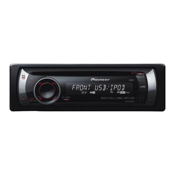
DEH-P3100UB
Installation Manual
Manuel d'installation
Manual de instalación
Printed in China
Imprimé en Chine
<YRD5275-A/S> UC
<KMINX> <08H00000>
Installation
English
2. Secure the mounting sleeve by
Note
using a screwdriver to bend the
• Check all connections and systems before final
metal tabs (90°) into place.
installation.
Mounting sleeve
• Do not use unauthorized parts. The use of
Dashboard
unauthorized parts may cause malfunctions.
• Consult with your dealer if installation requires
182
drilling of holes or other modifications of the
vehicle.
53
• Do not install this unit where:
— it may interfere with operation of the vehicle.
— it may cause injury to a passenger as a result
of a sudden stop.
• The semiconductor laser will be damaged if it
3. Install the unit.
overheats. Install this unit away from hot places
• Use commercially available parts when
such as near the heater outlet.
installing.
• Optimum performance is obtained when the unit
Nut
is installed at an angle of less than 60°.
Filrewall or
metal support
60°
Metal strap
Screw
DIN Front/Rear-mount
Screw (M4 8)
This unit can be properly installed either from
"Front" (conventional DIN Front-mount) or
"Rear" (DIN Rear-mount installation, utilizing
threaded screw holes at the sides of unit
chassis). For details, refer to the following
installation methods.
• Make sure that the unit is installed securely
in place. Unstable installation may cause this
DIN Front-mount
unit to malfunction, such as sound skip.
Removing the Unit
Installation with metal strap and
1. Extend top and bottom of the trim
screws
ring outwards to remove the trim
1. Insert the mounting sleeve into the
ring. When reattaching the trim
dashboard.
ring, push the trim ring onto the
• When installing in a shallow space, use a
unit until it clicks. (If the trim ring is
supplied mounting sleeve. If there is enough
space behind the unit, use factory supplied
attached upside down, the trim ring
mounting sleeve.
will not fit properly.)
• It becomes easy to remove the trim ring if the
front panel is released.
Trim ring
Installation
English
2. Insert the supplied extraction keys
3. Tighten two screws on each side.
• Use either truss screws (5 mm × 8 mm)
into both sides of the unit until
or flush surface screws (5 mm × 9 mm),
they click into place.
depending on the shape of screw holes in the
bracket.
Screw
Dashboard or Console
Factory radio mounting bracket
3. Pull the unit out of the dashboard.
Fastening the front panel
DIN Rear-mount
If you do not plan to detach the front panel,
1. Extend top and bottom of the trim
the front panel can be fastened with supplied
ring outwards to remove the trim
screw.
ring. When reattaching the trim ring,
push the trim ring onto the unit until
it clicks. (If the trim ring is attached
upside down, the trim ring will not
fit properly.)
Screw
• It becomes easy to remove the trim ring if the
front panel is released.
Trim ring
2. Determine the appropriate position
where the holes on the bracket and
the side of the unit match.
Connecting the unit
English
• Control signal is output through blue/white cable
Note
when this unit is powered on. Connect it to an
external power amp's system remote control or
• When this unit is installed in a vehicle without
the vehicle's auto-antenna relay control terminal
ACC (accessory) position on the ignition switch,
(max. 300 mA, 12 V DC). If the vehicle is equipped
red cable must be wired to the terminal that
with a glass antenna, connect it to the antenna
can detect the operation of the ignition key.
booster power supply terminal.
Otherwise, battery drain may result.
• Never connect blue/white cable to external
power amp's power terminal. Also, never connect
it to the power terminal of the auto antenna.
Otherwise, battery drain or malfunction may
result.
• IP-BUS connectors are color-coded. Be sure to
connect connectors of the same color.
• Black cable is ground. This cable and other
product's ground cable (especially, high-current
products such as power amp) must be wired
ACC position
No ACC position
separately. Otherwise, fire or malfunction may
result if they are accidentally detached.
• Use this unit in other than the following
conditions could result in fire or malfunction.
— Vehicles with a 12-volt battery and negative
grounding.
— Speakers with 50 W (output value) and 4 ohm
to 8 ohm (impedance value).
• To prevent short-circuit, overheating or
malfunction, be sure to follow the directions
below.
— Disconnect the negative terminal of the
battery before installation.
— Secure the wiring with cable clamps or
adhesive tape. To protect the wiring, wrap
adhesive tape around them where they lie
against metal parts.
— Place all cables away from moving parts, such
as gear shift and seat rails.
— Place all cables away from hot places, such
as near the heater outlet.
— Do not pass the yellow cable through a hole
into the engine compartment to connect to a
battery.
— Cover any disconnected cable connectors
with insulating tape.
— Do not shorten any cables.
— Never cut the insulation of the power cable of
this unit in order to share the power to other
equipment. Current capacity of the cable is
limited.
— Use a fuse of the rating prescribed.
— Never wire the speaker negative cable directly
to ground.
— Never band together multiple speaker's
negative cables.
Advertisement

Related Manuals for Pioneer DEH-P3100UB


Summary of Contents for Pioneer DEH-P3100UB
- Page 1 • Check all connections and systems before final RADIO CD installation. • Do not use unauthorized parts. The use of DEH-P3100UB unauthorized parts may cause malfunctions. • Consult with your dealer if installation requires drilling of holes or other modifications of the vehicle.
- Page 2 Connecting the unit English Connecting the unit When not connecting a rear speaker lead to a subwoofer This product To rear output or subwoofer output Rear output or subwoofer output To front output Antenna jack Front output Fuse (10 A) IP-BUS input (Blue) Multi-CD player IP-BUS cable...
-
Page 3: Installation
Installation Français Installation 2. Fixez le manchon de montage en Retrait de l’appareil Remarque utilisant un tournevis pour tordre 1. Étendez la partie supérieure et • Vérifiez toutes les connexions et tous les les languettes de métal (90°). systèmes avant l’installation finale. Manchon de montage •... - Page 4 Connexions des appareils Français Connexions des appareils Quand aucun câble d’enceinte arrière n’est connecté au caisson de grave À la sortie arrière Cet appareil ou sortie du caisson Sortie arrière ou de grave sortie du caisson de grave À la sortie avant Prise d’antenne Sortie avant Fusible (10 A)
-
Page 5: Instalación
Instalación Español Instalación 2. Fije el manguito de montaje Nota utilizando un destornillador para • Verifique todas las conexiones y sistemas antes doblar las lengüetas de metal (90°) de la instalación final. en posición. • No utilice piezas no autorizadas. El uso de piezas no autorizadas puede causar un fallo de Tablero de Manguito de montaje... - Page 6 Conexión de las unidades Español Conexión de las unidades Cuando no se conecta un cable de altavoz trasero a un altavoz de subgraves A la salida trasera o a la salida Este producto del altavoz de subgraves Salida trasera o salida de altavoz de subgraves A la salida Toma de antena...