
Related Manuals for AudioCodes October 2011


Summary of Contents for AudioCodes October 2011
- Page 1 Mediant™ 800 MSBG Multi-Service Business Gateway SIP Protocol Hardware Installation Manual Version 6.4 October 2011 Document # LTRT-10206...
-
Page 3: Table Of Contents
5.10 Connecting the Serial Interface to a PC ............... 40 5.11 Connecting the OSN Server................. 41 5.12 Powering up the Device ..................43 Maintenance – Replacing the Power Fuse ............. 45 A Notice for Installing CentOS Version 4.7 on OSN Server ......47 Version 6.4 October 2011... - Page 4 Mediant 800 MSBG List of Figures Figure 3-1: Front Panel .......................... 13 Figure 3-2: Rear Panel........................... 19 Figure 4-1: Rubber Foot Attached to Underside of Device ..............21 Figure 4-2: Peeled-off Rubber Foot ....................... 21 Figure 4-3: Mounting Bracket (Right) ..................... 23 Figure 4-4: Attaching the Mounting Brackets ..................
- Page 5 Table 5-2: RJ-45 Connector Pinouts for SHDSL ................... 29 Table 5-3: Connector Pinouts for ADSL/VDSL ..................30 Table 5-4: RJ-45 Connector Pinouts for GbE/FE with PoE ..............32 Table 6-1: Allowed Fuses for the Device ....................45 Version 6.4 October 2011...
- Page 6 Mediant 800 MSBG Reader's Notes Hardware Installation Manual Document #: LTRT-10206...
- Page 7 This document is subject to change without notice. Date Published: October-3-2011 Trademarks AudioCodes, AC, AudioCoded, Ardito, CTI2, CTI², CTI Squared, HD VoIP, HD VoIP Sounds Better, InTouch, IPmedia, Mediant, MediaPack, NetCoder, Netrake, Nuera, Open Solutions Network, OSN, Stretto, TrunkPack, VMAS, VoicePacketizer, VoIPerfect, VoIPerfectHD, What’s Inside Matters, Your Gateway To VoIP and 3GX are trademarks or...
- Page 8 Note: Open source software may have been added and/or amended for this product. further information, please visit website http://audiocodes.com/support contact your AudioCodes sales representative. Warnings and Safety Information Caution Electrical Shock Do not open or disassemble this device. The device carries high voltage and contact with internal components may expose you to electrical shock and bodily harm.
-
Page 9: Introduction
This document provides a hardware description of the Mediant 800 MSBG (hereafter referred to as device) and step-by-step procedures for cabling the device. Note: For information on configuring the device, refer to the device's User’s Manual. Version 6.4 October 2011... - Page 10 Mediant 800 MSBG Reader’s Notes Hardware Installation Manual Document #: LTRT-10206...
-
Page 11: Unpacking The Device
• T1 WAN splitter cable (only for models with T1 WAN interface) • One AC power cable Check, retain and process any documents. If there are any damaged or missing items, notify your AudioCodes sales representative. Version 6.4 October 2011... - Page 12 Mediant 800 MSBG Reader's Notes Hardware Installation Manual Document #: LTRT-10206...
-
Page 13: Physical Description
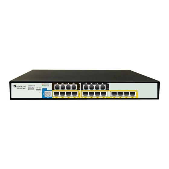
The device's front panel is shown in the figure below and described in the subsequent table. Figure 3-1: Front Panel Note: The figure above is used only as an example. The number and type of port interfaces depends on the ordered model. Version 6.4 October 2011... -
Page 14: Table 3-2: Front-Panel Description Of Ports And Buttons
Mediant 800 MSBG Table 3-2: Front-Panel Description of Ports and Buttons Item # Label Description USB/WWAN USB port for connecting an optional 3G cellular WAN modem. RS-232 RS-232 port for serial communication. POWER / LEDs indicating the status of the power, reboot/initialization, and WAN STATUS / WAN interface. -
Page 15: Leds
A valid PoE load is connected to the port, but the device has Flashing insufficient power to supply the required power load - PoE is not activated. No power load is present on the port output lines - PoE is not activated. Version 6.4 October 2011... -
Page 16: Wan Led
Mediant 800 MSBG 3.2.2.3 WAN LED The WAN port provides a LED for indicating operating status, as described in the table below. Table 3-5: WAN LED Description Description Color State Green WAN link established. Flashing Data is being received or transmitted. No WAN link. -
Page 17: Bri Led Description
Operational Status LED The STATUS LED indicates the operating status, as described in the table below. Table 3-10: STATUS LED Description Description Color State Green The device is operational. Flashing The device is rebooting. Boot failure. Version 6.4 October 2011... -
Page 18: Power Led
Mediant 800 MSBG 3.2.2.9 Power LED The POWER LED indicates the operating status, as described in the table below. Table 3-11: POWER LED Description Description Color State Green Power is received by the device. No power received by the device. Hardware Installation Manual Document #: LTRT-10206... -
Page 19: Rear Panel Description
OSN server. For example, one port can be connected to the LAN (to IP Phones) and the second port to the WAN interface (to an IP PBX). Protective earthing screw. 100-240V~1.5A 3-Prong AC power supply entry. 50-60Hz Version 6.4 October 2011... - Page 20 Mediant 800 MSBG Reader’s Notes Hardware Installation Manual Document #: LTRT-10206...
-
Page 21: Mounting The Device
Peel off the adhesive, anti-slide rubber feet and stick one in each anti-slide groove. Figure 4-2: Peeled-off Rubber Foot Flip the device over again so that it rests on the rubber feet and place it in the required position on a desktop. Version 6.4 October 2011... -
Page 22: 19-Inch Rack Mounting
Mediant 800 MSBG 19-Inch Rack Mounting The device can be installed in a standard 19-inch rack by implementing one of the following mounting methods: Placing it on a pre-installed shelf in a 19-inch rack – see Section 4.2.1 on page ... -
Page 23: Using Mounting Brackets
Place the device on a pre-installed shelf in the rack. Attach the ends of the mounting brackets (that you installed in Step 1) to the vertical track of the rack's frame, using standard 19-inch rack bolts (not supplied). Version 6.4 October 2011... - Page 24 Mediant 800 MSBG Reader's Notes Hardware Installation Manual Document #: LTRT-10206...
-
Page 25: Cabling The Device
(located on the rear panel), using the supplied washer. Connect the other end of the strap to a protective earthing. This should be in accordance with the regulations enforced in the country of installation. Figure 5-1: Earthing the Device Version 6.4 October 2011... -
Page 26: Connecting To Wan
Mediant 800 MSBG Connecting to WAN This section provides a description on how to cable the WAN port. The cabling procedure depends on the ordered WAN interface: Gigabit Ethernet (GbE) – see Section 5.2.1 on page T1 WAN – see Section 5.2.2 on page ... -
Page 27: Table 5-1: Rj-45 Connector Pinouts For Gigabit Ethernet Wan
The RJ-45 connector pinouts are described in the table below: Table 5-1: RJ-45 Connector Pinouts for Gigabit Ethernet WAN Signal Name Ethernet signal pair Ethernet signal pair Ethernet signal pair Ethernet signal pair Shield Chassis ground Version 6.4 October 2011... -
Page 28: T1 Wan Dsu/Csu Cabling
Mediant 800 MSBG 5.2.2 T1 WAN DSU/CSU Cabling The procedure below describes how to connect to the WAN through a dual T1 line interface (according to ANSI T1.403-1999). The dual T1 WAN DSU/CSU port interface transmits and receives data using IP over Point-to-Point Protocol (PPP), IP over High-Level Data Link Control (HDLC), or IP over Multilink Point-to-Point Protocol (MLP) framing. -
Page 29: Shdsl Wan Cabling
Connect the other end of the cable to the access point. The RJ-45 connector pinouts are described in the table below: Table 5-2: RJ-45 Connector Pinouts for SHDSL Function CH0-TIP CH0-RING CH1-TIP CH1-RING CH2-TIP CH2-RING CH3-TIP CH3-RING Version 6.4 October 2011... -
Page 30: Adsl And Vdsl Wan Cabling
Mediant 800 MSBG 5.2.4 ADSL and VDSL WAN Cabling The ADSL/VDSL WAN port provides a single ADSL/VDSL interface through its RJ-45 port. The specifications of the ADSL/VDSL interface include the following: ADSL: • RFC 2684 in Routed (IPoA) and Bridged (ETHoA) modes, supporting LLC-SNAP and VC-Multiplexed encapsulations over AAL5 •... -
Page 31: 3G/3.5G Cellular Wan Usb Modem Cabling
Plug a 3G cellular USB modem into the USB port located on the front panel and labeled USB/WWAN. Figure 5-7: Plugging the 3G Cellular Modem into the USB Port Note: For configuring the 3G cellular WAN support, refer to the User's Manual. Version 6.4 October 2011... -
Page 32: Connecting To Lan
Mediant 800 MSBG Connecting to LAN The device provides up to four Gigabit Ethernet (10/100/1000Base-T) LAN RJ-45, ports and eight RJ-45 10/100Base-TX (Fast Ethernet) LAN ports for connection to the LAN (e.g., computers, switches, and IP phones). These ports support half- and full-duplex modes, auto-negotiation, and straight or crossover cable detection. -
Page 33: Connecting Poe-Enabled Clients To Lan Ports
Upon device startup, PoE is enabled on all ports. • You can configure the maximum port power consumption (up to 15.4W) used when the plugged-in client is detected as Class 0. For more information, refer to the User's Manual. Version 6.4 October 2011... -
Page 34: Figure 5-9: Connecting Poe-Enabled Equipment To Lan Ports
Mediant 800 MSBG To connect PoE-enabled equipment to the PoE-enabled LAN ports: Connect one end of a straight-through RJ-45 Cat 5e or Cat 6 cable to a LAN port enabled with PoE. Connect the other end of the cable to PoE-enabled equipment (e.g., an IP Phone). Figure 5-9: Connecting PoE-enabled Equipment to LAN Ports Hardware Installation Manual Document #: LTRT-10206... -
Page 35: Connecting To Fxs Interfaces
Connect one end of an RJ-11 cable to the FXS port (labeled FXS). Figure 5-11: Connecting FXS Interfaces Connect the other end of the cable to the required telephone interface (e.g., fax machine, dial-up modem, and analog POTS telephone). Version 6.4 October 2011... -
Page 36: Connecting To Fxo Interfaces
Mediant 800 MSBG Connecting to FXO Interfaces The procedure below describes how to cable the device's FXO interfaces. Warnings: • To protect against electrical shock and fire, use a minimum 26-AWG wire to connect FXO ports to the PSTN. • Ensure that the FXO ports are connected to the appropriate, external devices;... -
Page 37: Connecting To Analog Lifeline Phone
For the combined FXS/FXO configuration, one Lifeline is available; for the 12-FXS configuration, up to three Lifelines are available. • The scenarios upon which Lifeline is activated is configured by the LifeLineType ini file parameter (for more information, refer to the User's Manual). Version 6.4 October 2011... -
Page 38: Connecting To Isdn Bri Lines
Mediant 800 MSBG Connecting to ISDN BRI Lines The device provides up to four BRI S/T ports. These ports connect to ISDN terminal equipment such as ISDN telephones. Each BRI port can be configured either as termination equipment/user side (TE) or network termination/network side (NT). Up to eight terminal equipment (TE) devices can be connected per BRI S/T port, using an ISDN S-bus that provides eight ISDN ports. -
Page 39: Connecting To Isdn Pri (E1/T1) Trunks
Figure 5-18: RJ-48c Connector Pinouts for E1/T1 To connect the E1/T1 trunk interface: Connect the E1/T1 trunk cable to the device’s E1/T1 port. Connect the other end of the trunk cable to your PBX/PSTN switch. Figure 5-19: Cabling E1/T1 Ports Version 6.4 October 2011... -
Page 40: Connecting The Serial Interface To A Pc
Mediant 800 MSBG 5.10 Connecting the Serial Interface to a PC The device provides an RS-232 serial interface port on its front panel. The serial cable adapter used for connecting the RS-232 interface is shown below: Figure 5-20: RS-232 Cable Adapter ... -
Page 41: Connecting The Osn Server
Ethernet ports on the rear panel, you can use the LAN port #1 located on the front panel for connecting to the OSN server. • If your device is shipped with an OSN server, you can download the latest OSN drivers from AudioCodes Web site at http://www.audiocodes.com/downloads. To connect the OSN server:... - Page 42 Mediant 800 MSBG To reset the OSN server: Insert a sharp-pointed object (such as a drawing pin) into the Reset pinhole and then extract it after a second; the OSN server performs a reset. Hardware Installation Manual Document #: LTRT-10206...
-
Page 43: Powering Up The Device
Connect the plug at the other end of the AC power cord to a standard electrical outlet. Once you have cabled and powered-up the device, the POWER LED on the front panel lights up green. For a description of this LED, see Section 3.2.2.9 on page 18. Version 6.4 October 2011... - Page 44 Mediant 800 MSBG Reader’s Notes Hardware Installation Manual Document #: LTRT-10206...
-
Page 45: Maintenance - Replacing The Power Fuse
Carefully remove the fuse from the fuse cavity. Figure 6-2: Removing the Power Fuse Insert the new fuse securely into the fuse cavity until you hear a click sound. Reconnect the power cord and verify that the Power LED is lit green. Version 6.4 October 2011... - Page 46 Mediant 800 MSBG Reader's Notes Hardware Installation Manual Document #: LTRT-10206...
-
Page 47: A Notice For Installing Centos Version 4.7 On Osn Server
When installing CentOS, ensure that you type linux irqpoll at the boot: prompt. For CentOS to identify the OSN server’s Gigabit Ethernet (GE) interfaces, do the following: Obtain the following files from AudioCodes: ♦ Binary compiled CentOS 4.7 driver for Intel e1000e Ethernet controller on Mediant 800 MSBG (e1000e.ko) ♦... - Page 48 Hardware Installation Manual Ver. 6.4 www.audiocodes.com...