Advertisement
Quick Links
Safe Operation Practices • Assembly & Set-Up • Controls & Operation • Product Care
Table of Contents
Safe Operation Practices ........................................ 2
Assembly & Set-Up .................................................. 7
Controls & Operation .............................................. 8
Product Care ...........................................................12
READ AND FOLLOW ALL SAFETY RULES AND INSTRUCTIONS IN THIS MANUAL
FAILURE TO COMPLY WITH THESE INSTRUCTIONS MAY RESULT IN PERSONAL INJURY.
NOTE: This Operator's Manual covers several models. Features may vary by model. Not all features in this manual are applicable to all
models and the model depicted may differ from yours.
O
peratOr
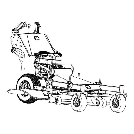
Pro HW336
BEFORE ATTEMPTING TO OPERATE THIS MACHINE.
'
M
s
anual
Replacement Parts ................................................ 20
Attachments & Accessories .................................. 20
Warranty ................................................................ 21
WARNING
Form No. 769-19271A
(July 10, 2020)
Advertisement

Related Manuals for Cub Cadet Pro HW336


Summary of Contents for Cub Cadet Pro HW336
-
Page 1: Table Of Contents
Safe Operation Practices • Assembly & Set-Up • Controls & Operation • Product Care ’ peratOr anual Pro HW336 Table of Contents Safe Operation Practices ........2 Replacement Parts ..........20 Assembly & Set-Up ..........7 Attachments & Accessories ........20 Controls &... -
Page 2: Safe Operation Practices
Safe Operation Practices WARNING This symbol points out important safety instructions which, if not followed, could endanger the personal safety and/or property of yourself and others. Read and follow all instructions in this manual before attempting to operate this machine. Failure to comply with these instructions may result in personal injury. When you see this symbol. HEED ITS WARNING! WARNING California Proposition 65 Engine Exhaust, some of its constituents, and certain vehicle components contain or emit chemicals known to the State of California to cause cancer and birth defects or other reproductive harm. - Page 3 Hydraulic Devices & Systems When operating this machine in the If the fuel tank has to be drained, do forward or reverse direction, do not this outdoors. allow the ground speed control levers Hydraulic fluid escaping under pressure may Never remove gas cap or add fuel while to return to the neutral position on their have sufficient force to penetrate skin and to engine is hot or running.
- Page 4 Do not modify engine Spark Arrestor Never attempt to make a wheel or cutting height adjustment while the engine is running. To avoid serious injury or death, do not WARNING modify engine in any way. Tampering with Grass catcher components, discharge the governor setting can lead to a runaway cover, and trail shield are subject to This machine is equipped with an internal combustion...
- Page 5 Safety Symbols This page depicts and describes safety symbols that may appear on this product. Read, understand, and follow all instructions on the machine before attempting to assemble and operate. Symbol Description READ THE OPERATOR’S MANUAL(S) Read, understand, and follow all instructions in the manual(s) before attempting to assemble and operate.
- Page 6 1 — S ection peration racticeS...
-
Page 7: Assembly & Set-Up
Assembly & Set-Up Thank You Thank you for purchasing this product. It was carefully engineered to provide manual may not be applicable to all models. We reserve the right to change excellent performance when properly operated and maintained. product specifications, designs and equipment without notice and without incurring obligation. -
Page 8: Controls & Operation
Controls & Operation Steering Levers (E) The steering levers are located under the left and right handles. When the levers are released, the mower will move ahead in a straight line if the engine is running and the transmission is engaged STOP STOP in a forward gear. - Page 9 Hour Meter (J) Transmission Bypass Levers (Not Shown) Note: If the engine is warmed up, it may not be necessary to engage the choke. Move the throttle lever midway between the FAST and SLOW position. Note: When operating the mower be certain that the throttle lever is always in the FAST The hour meter is located on the upper section of position.
- Page 10 Engaging the Drive WARNING Do not leave the operator’s position without first disengaging WARNING the PTO. If leaving the mower unattended, also turn the Avoid sudden starts, excessive speed and sudden stops. engine off and remove the ignition key. Start the engine as instructed earlier in this Engaging the Blades section and move the throttle control into the FAST position.
- Page 11 • To prevent rutting or grooving of the • For emptying material collection systems or Transporting Mower turf, change the direction that the for any other operation involving the mower • If ramps are used, be sure they are secured to strips are mowed by approximately 45 deck, before leaving the operator station: the trailer, truck bed, etc.
-
Page 12: Product Care
Product Care Maintenance Schedule Before Every Every Prior 1st Five Hours Every 300 Hours Each use 40 Hours 100 Hours to Storing Check/Clean Engine Intake Screens & Cooling Fans * Check/Clean Exhaust Manifold, Muffler Pipe & Muffler Shields * Check/Clean Top & Underside of Deck, Under and Around Spindle Covers & Belt Area * Check/Clean Around Fuses, Wiring &... - Page 13 Note: This Operator’s Manual covers several Storing the Mower • Clean around the exhaust manifold, fuses, all wiring and harnesses, muffler pipe, models. Mower features may vary by model. • Allow the machine to cool in an open muffler shield, engine intake screens and Not all features in this manual are applicable area before storing.
- Page 14 After draining the oil, wipe any residual Battery Storage Using the Transmission Bypass Rods oil from the oil drain hose. Thread the When storing the mower for extended If for any reason the mower will not drive square head plug into the drain hose or you wish to move the mower, the two periods, disconnect the negative battery fitting and fully tighten the plug.
- Page 15 If necessary to add oil because of some Clean the engine and the entire There are four adjustment points on the type of leakage, use a quality 20W50 motor mower thoroughly. deck. Each of the deck lift adjustment oil and add only enough oil to bring the pins has an adjustment bolt (a).
- Page 16 Insert the hex screw (c) into one of three • Make certain that the engine will not Using a 1⁄2” drive in the idler pulley index holes in the front gauge wheel start unless the key switch is turned on, bracket (a), turn the wrench counter- bracket (e) that will give the front gauge the transmission is in neutral and the...
- Page 17 Replacing the Deck Belt Replacing the Blades Sharpening the Blades Set the parking brake. Set the parking brake. Remove ignition WARNING key and both spark plug caps. Clean any debris from the blades. Keep blades sharp and free of build up at Before performing any maintenance, disengage the Remove the deck, (refer to all times.
- Page 18 Changing the Spindle Assembly Mower Creeping Loosen the jam nut (a) and zero out the transmission. See Figure 4-23. Perform Remove the deck as instructed in the Creeping is the slight forward or backward on both sides of the mower. Deck Removal section.
- Page 19 Troubleshooting Mower will not mulch grass. Mower drifting Engine speed too low. Mower tracking needs adjusted. Excessive vibration • Place throttle in FAST • Adjust mower tracking. (rabbit) position. Cutting blade loose or unbalanced. Engine fails to start Wet grass. •...
-
Page 20: Replacement Parts
Replacement Parts Part Number Description 954-05703 36” Deck Belt 954-05812 Drive Belt 942-05458 Hi-Lift Blade, 18.5 (36” Deck) 618-07406 Deck Spindle 731-13254 Deck Skid Guard, 36” Deck 925-1707D Battery (Electric Start Models Only) 751-15884 Gas Cap 946-05434 Throttle Control Cable (If Equipped) 946-05341B Choke Control (If Equipped) 925-06908... -
Page 21: Warranty
MTD Product Warranty Statutory Warranty If you are a “consumer” pursuant to the Australian Consumer Law, then MTD Products Australia Pty Ltd ACN 004 873 572 (MTD) confirms the following: Our goods come with guarantees that cannot be excluded under the Australian Consumer Law. You are entitled to a replacement or refund for a major failure and for compensation for any other reasonably foreseeable loss or damage. - Page 22 TABLE A General Warranty General Warranty Period Commercial Period Domestic Use Attachments Warranty LAWN MOWERS Engine Warranty Period Period Excludes engine, attachments and normal wear parts 5 Year Domestic / 90 Day Rover Steel Deck / Rover Engine/Endeavor 2 Years 90 Days Commercial 2 Year Domestic / 90 Day...
- Page 23 TABLE A CONTINUED General Warranty General Warranty Period Commercial Period Domestic Use Attachments Warranty ROVER RIDE ONS & ZERO- TURNS Engine Warranty Period Period Excludes engine, attachments and normal wear parts 2 Year Domestic / 90 1 Year Domestic / 90 Day Micro Rider 24"...
- Page 24 TABLE A CONTINUED General Warranty CUB CADET RIDE ONS & ZERO- General Warranty Period Commercial Engine Warranty Period Attachment Warranty Period TURNS Period Domestic Use Excludes engine, attachments and normal wear parts CC30 e (Electric Rider) 3 Years 90 Days...
- Page 25 1 year General Warranty General Warranty Period Period Domestic Use Commercial CUB CADET COMMERCIAL PRO Z Engine Warranty Period Attachments Warranty Period Excludes engine, attachments and normal wear parts 3 Years. 3 Year Domestic / 3 Year PRO Z 148 S...
- Page 26 General Warranty Period Domestic & WOLF- Garten Engine Warranty Period Attachments Warranty Period Commercial Use WOLF-Garten multi-Star® unit system, multi-star® Minis and the multi-star® tree Lifetime care without ladder Hand tools and all manually controlled 10 years trimmers For the purpose of Table A: “Attachments”...
- Page 27 any failure arising from accident, abuse, act of God, fire, sabotage, vandalism, contaminated fluids or neglect or failure to operate, store and/or maintain and service the MTD Product in accordance with the instruction manual supplied with the MTD Product; any parts or services required for the normal and regular maintenance of the MTD Product e.g.
- Page 28 MTD Product; proof of purchase with purchase date; evidence of warranty registration; and full details of the alleged MTD Product defect. to an authorised MTD dealer upon discovery of any defect in the MTD Product, and within the relevant Warranty Period. Your nearest MTD dealer can be found at cubcadet.com.au, rover.com.au or mtd.com.au.