
Related Manuals for Supermicro X11SDW-12C-TP13F


Summary of Contents for Supermicro X11SDW-12C-TP13F
- Page 1 X11SDW-4C-TP13F X11SDW-8C-TP13F X11SDW-12C-TP13F X11SDW-14C-TP13F X11SDW-14CNT-TP13F X11SDW-16C-TP13F USER MANUAL Revision 1.0c...
- Page 2 State of California, USA. The State of California, County of Santa Clara shall be the exclusive venue for the resolution of any such disputes. Supermicro's total liability for all claims will not exceed the price paid for the hardware product.
- Page 3 . I t p r o v i d e s i n f o r m a t i o n f o r t h e i n s t a l l a t i o n a n d u s e o f t h e X11SDW-4C/8C/12C/14C/14CNT/16C-TP13F motherboard. About This Motherboard The Supermicro X11SDW-4C/8C/12C/14C/14CNT/16C-TP13F motherboard supports an Intel® Xeon D-2100 SoC processor. This a high performance, proprietary form factor motherboard that is ideal for embedded networking and storage systems. The latest features for this motherboard inlcude support for 13 LAN ports with dual 10GbE SFP+ and dual 10Gbase-T ports, M.2 M-Key/B-Key/E-Key connections, and an NVMe connection.
- Page 4 Super X11SDW-4C/8C/12C/14C/14CNT/16C-TP13F User's Manual Contacting Supermicro Headquarters Address: Super Micro Computer, Inc. 980 Rock Ave. San Jose, CA 95131 U.S.A. Tel: +1 (408) 503-8000 Fax: +1 (408) 503-8008 Email: Marketing@supermicro.com (General Information) Sales-USA@supermicro.com (Sales Inquiries) Government_Sales-USA@supermicro.com (Gov. Sales Inquiries) Support@supermicro.com (Technical Support) RMA@supermicro.com...
-
Page 5: Table Of Contents
Preface Table of Contents Chapter 1 Introduction 1.1 Checklist ..........................8 Quick Reference .......................11 Quick Reference Table ......................13 Motherboard Features .......................15 1.2 Processor Overview ......................19 1.3 Special Features ........................19 Recovery from AC Power Loss ..................19 1.4 System Health Monitoring ....................20 Onboard Voltage Monitors ....................20 Fan Status Monitor with Firmware Control ...............20 System Resource Alert......................20 1.5 ACPI Features ........................21... - Page 6 Super X11SDW-4C/8C/12C/14C/14CNT/16C-TP13F User's Manual 2.6 Connectors and Headers ....................37 2.7 Jumper Settings .........................51 How Jumpers Work ......................51 2.8 LED Indicators ........................58 Chapter 3 Troubleshooting 3.1 Troubleshooting Procedures ....................61 Before Power On ......................61 No Power ..........................61 No Video ...........................61 System Boot Failure ......................62 Memory Errors ........................62 Losing the System's Setup Configuration .................63 When the System Becomes Unstable ................63...
- Page 7 Preface Appendix A BIOS Codes A.1 BIOS Error POST (Beep) Codes ..................112 A.2 Additional BIOS POST Codes ..................113 Appendix B Software Installation B.1 Installing Software Programs ...................114 B.2 SuperDoctor 5 .........................115 ® Appendix C Standardized Warning Statements Battery Handling ......................116 Product Disposal ......................118 Appendix D UEFI BIOS Recovery D.1 Overview ...........................119...
-
Page 8: Chapter 1 Introduction
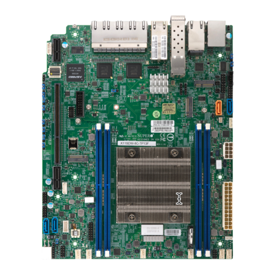
Introduction Congratulations on purchasing your computer motherboard from an acknowledged leader in the industry. Supermicro boards are designed with the utmost attention to detail to provide you with the highest standards in quality and performance. Please check that the following items have all been included with your motherboard. If anything listed here is damaged or missing, contact your retailer. - Page 9 Chapter 1: Introduction Figure 1-1. [motherboard model4] Motherboard Image...
- Page 10 Super X11SDW-4C/8C/12C/14C/14CNT/16C-TP13F User's Manual Figure 1-2. X11SDW-4C-TP13F Motherboard Layout (not drawn to scale) PRESS FIT LED2 JBM2 JSXB1A LED3 COM1 USB 4/5 LAN 2/3/4/5/6/7/8/9 LAN 1 IPMI_LAN LAN 10/11 JPL1 LEDM1 JSDP3 JPI2C1 JLANLED1 JTGLED2 LAN 12/13 JBM1 JMD3:M.2-P PCI-E 3.0 X1 JTGLED1 JVGA1 COM2...
-
Page 11: Quick Reference
Chapter 1: Introduction Quick Reference LAN12/13 LAN1 LAN10/11 IPMI LAN JSDP3 LED2 JTGLED2 LED3 LAN2-9 COM1 JBM1 USB4/5 JBM2 PRESS FIT LED2 JBM2 JSXB1A JSXB1A LED3 JIPMB1 COM1 USB 4/5 JPUSB1 LAN 2/3/4/5/6/7/8/9 LAN 1 IPMI_LAN LEDM1 JPL1 LAN 10/11 JPL1 LEDM1 JLANLED1... - Page 12 Super X11SDW-4C/8C/12C/14C/14CNT/16C-TP13F User's Manual Figure 1-3. X11SDW-TP13F Series Motherboard Model Variation Table X11SDW-TP13F Series Motherboard Model Variation Table Motherboard Model Name X11SDW-4C- X11SDW-8C- X11SDW-12C- X11SDW-14C- X11SDW- X11SDW-16C- TP13F TP13F TP13F TP13F 14CNT-TP13F TP13F Processor Name D-2123IT D-2146NT D-2163IT D-2173IT D-2177NT D-2183IT Number of Cores Number of Threads...
-
Page 13: Quick Reference Table
Chapter 1: Introduction Quick Reference Table Jumper Description Default Setting M.2 SMBus Enable/Disable Pins 1-2 (Enabled) JBM1 IPMI Share LAN Enable/Disable Open: Enabled (Default) Closed: Disabled JBM2 IPMI Dedicated/Share LAN Enable/Disable Open: Enabled (Default) Closed: Disabled JBT1 CMOS Clear Open: Normal Closed: Clear CMOS C1/JI SMB to PCIe Slots Enable/Disable... - Page 14 Super X11SDW-4C/8C/12C/14C/14CNT/16C-TP13F User's Manual Connector Description JMD3 M.2 Slot E-Key 2230 (USB2.0 / PCIe x1) JNVI2C1 Non-volatile Memory (NVMe) I C Header JPH1 4-pin HDD Power Connector Power I2C System Management Bus (Power SMB) Header JPV1 12V 8-pin DC Power Connector (Required to provide extra power to the CPU, or as alternative power for special enclosure when the 24 pin ATX power is not in use) JPW1 GPU Power Connector...
-
Page 15: Motherboard Features
Chapter 1: Introduction Motherboard Features Motherboard Features • Intel® Xeon D-2100 SoC Series SoC with a TDP of up to 105W Memory • Supports up to 256GB of ECC RDIMM or 512GB of ECC LRDIMM DDR4 memory with speeds of up to 2667MHz. DIMM Size •... - Page 16 Super X11SDW-4C/8C/12C/14C/14CNT/16C-TP13F User's Manual Motherboard Features Power Management • ACPI power management • CPU fan auto-off in sleep mode • Power button override mechanism • Power-on mode for AC power recovery System Health Monitoring • Onboard voltage monitors for CPU cores, +1.8V, +3.3V, +5V, +/-12V, +3.3V Stby, +5V Stby, VBAT, HT, Memory, PCH temperature, system temperature, and memory temperature •...
- Page 17 Note 2: For IPMI configuration instructions, please refer to the Embedded IPMI Con- figuration User's Guide available at http://www.supermicro.com/support/manuals/. Note 3: If you purchase a Supermicro Out of Band (OOB) software license key (Supermicro P/N: SFT-OOB--LIC), please do not change the IPMI MAC address. Once...
- Page 18 Super X11SDW-4C/8C/12C/14C/14CNT/16C-TP13F User's Manual Figure 1-4. Chipset Block Diagram Note: This is a general block diagram and may not exactly represent the features on your motherboard. See the previous pages for the actual specifications of your moth- erboard.
-
Page 19: Processor Overview
Chapter 1: Introduction 1.2 Processor Overview The Intel Xeon D-2100 series SoC processor family, with up to 16 cores and up to 105W of power, offers performance, reliability, and high intelligence. As a low-power system-on-a-chip motherboard, the X11SDW-4C/8C/12C/14C/14CNT/16C-TP13F is optimized for a variety of workloads that requires high compute power in a compact form-factor. -
Page 20: System Health Monitoring
Super X11SDW-4C/8C/12C/14C/14CNT/16C-TP13F User's Manual 1.4 System Health Monitoring The motherboard has an onboard Baseboard Management Controller (BMC) chip that supports system health monitoring. Onboard Voltage Monitors The onboard voltage monitor will continuously scan crucial voltage levels. Once a voltage becomes unstable, it will give a warning or send an error message to the screen. Users can adjust the voltage thresholds to define the sensitivity of the voltage monitor. -
Page 21: Acpi Features
Chapter 1: Introduction 1.5 ACPI Features The Advanced Configuration and Power Interface (ACPI) specification defines a flexible and abstract hardware interface that provides a standard way to integrate power management features throughout a computer system, including its hardware, operating system and application software. -
Page 22: Chapter 2 Installation
Super X11SDW-4C/8C/12C/14C/14CNT/16C-TP13F User's Manual Chapter 2 Installation 2.1 Static-Sensitive Devices Electrostatic Discharge (ESD) can damage electronic com ponents. To prevent damage to your motherboard, it is important to handle it very carefully. The following measures are generally sufficient to protect your equipment from ESD. Precautions •... -
Page 23: Motherboard Installation
Chapter 2: Installation 2.2 Motherboard Installation All motherboards have standard mounting holes to fit different types of chassis. Make sure that the locations of all the mounting holes for both the motherboard and the chassis match. Although a chassis may have both plastic and metal mounting fasteners, metal ones are highly recommended because they ground the motherboard to the chassis. -
Page 24: Installing The Motherboard
Super X11SDW-4C/8C/12C/14C/14CNT/16C-TP13F User's Manual Installing the Motherboard 1. Locate the mounting holes on the motherboard. See the previous page for the location. 2. Locate the matching mounting holes on the chassis. Align the mounting holes on the motherboard against the mounting holes on the chassis. 3. -
Page 25: Memory Support And Population
Chapter 2: Installation 2.3 Memory Support and Population Important: Exercise extreme care when installing or removing DIMM modules to pre- vent any possible damage. Memory Support The X11SDW-4C/8C/12C/14C/14CNT/16C-TP13F motherboard supports up to 256GB of ECC RDIMM or 512GB of ECC LRDIMM DDR4 memory in four memory slots. Populating these DIMM slots with memory modules of the same type and size will result in interleaved memory, which will improve memory performance. -
Page 26: Dimm Module Population Sequence
Super X11SDW-4C/8C/12C/14C/14CNT/16C-TP13F User's Manual DIMM Module Population Sequence When installing memory modules, the DIMM slots should be populated in the following order: DIMMA1, DIMMB1, DIMMD1, DIMME1. • It's recommended to use DDR4 DIMM modules of the same type and speed. •... -
Page 27: Dimm Installation
Chapter 2: Installation DIMM Installation PRESS FIT LED2 JBM2 1. Insert the desired number of DIMMs into JSXB1A LED3 COM1 USB 4/5 LAN 2/3/4/5/6/7/8/9 the memory slots, starting with DIMMA1, LAN 1 IPMI_LAN LAN 10/11 JPL1 LEDM1 JSDP3 JPI2C1 JLANLED1 DIMMB1, DIMMD1, DIMME1. -
Page 28: Rear I/O Ports
Super X11SDW-4C/8C/12C/14C/14CNT/16C-TP13F User's Manual 2.4 Rear I/O Ports See the figure below for the locations and descriptions of the various I/O ports on the rear of the motherboard. PRESS FIT LED2 JBM2 JSXB1A LED3 COM1 USB 4/5 LAN 2/3/4/5/6/7/8/9 LAN 1 IPMI_LAN LAN 10/11 JPL1... - Page 29 Chapter 2: Installation LAN Ports The motherboard has 13 LAN ports. LAN1 – LAN9 are 1G ports, LAN10 – LAN11 are 10G ports, and LAN12 – LAN13 are 10G SFP+ ports. In addition to the LAN ports, the motherboard offers a dedicated IPMI LAN port. Refer to the table below for the pin definitions. LAN Port Pin Definition Pin#...
- Page 30 Super X11SDW-4C/8C/12C/14C/14CNT/16C-TP13F User's Manual COM Port/Header The motherboard has one COM port on the back panel I/O and one COM header on the motherboard to provide serial connections. COM Port Pin Definitions Pin# Definition Pin# Definition SP_DCDA SP_DSRA SP_RXDA SP_RTSA SP_TXDA SP_STSA SP_DTRA...
- Page 31 Chapter 2: Installation Universal Serial Bus (USB) Ports The motherboard has two USB 3.0 Gen 1 ports (USB4/5) on the I/O back panel. There are two USB 2.0 headers (USB0/1, USB2/3). These onboard headers can be used to provide front side USB access with a cable (not included). USB4/5 (USB 3.0 Type A) Front Panel USB 2.0 Header Pin Definitions...
- Page 32 Note: UID can also be triggered via IPMI on the motherboard. For more information on IPMI, please refer to the IPMI User's Guide posted on our website at http://www. supermicro.com/support/manuals/. UID LED UID Button Pin Definitions...
-
Page 33: Front Control Panel
JF1 contains header pins for various buttons and indicators that are normally located on a control panel at the front of the chassis. These connectors are designed specifically for use with Supermicro chassis. See the figure below for the descriptions of the front control panel buttons and LED indicators. - Page 34 Super X11SDW-4C/8C/12C/14C/14CNT/16C-TP13F User's Manual Power Button The Power Button connection is located on pins 1 and 2 of JF1. Momentarily contacting both pins will power on/off the system. This button can also be configured to function as a suspend button (with a setting in the BIOS - see Chapter 4). To turn off the power in the suspend mode, press the button for at least seconds seconds.
- Page 35 Chapter 2: Installation Overheat (OH)/Fan Fail Connect an LED cable to OH/Fan Fail connections on pins 7 and 8 of JF1 to provide warnings for chassis overheat and fan failure. Refer to the table below for pin definitions. OH/Fan Fail LED OH/Fan Fail Indicator Pin Definitions (JF1) Pin Definitions...
- Page 36 Super X11SDW-4C/8C/12C/14C/14CNT/16C-TP13F User's Manual HDD LED The HDD LED connection is located on pins 13 and 14 of JF1. Attach a cable here to show hard drive activity status. Refer to the table below for pin definitions. HDD LED Pin Definitions (JF1) Pins Definition +3.3V...
-
Page 37: Connectors And Headers
Chapter 2: Installation 2.6 Connectors and Headers Power Connectors The primary ATX power supply connector (JPWR1) meets the ATX SSI EPS 12V specification. JPV1 is the 12V DC power connector that provides power to the motherboard. JPH1 is a 4-pin HDD power connector that provides power to onboard hard disk drives. ATX Power 24-pin Connector 8-pin 12V Power Pin Definitions... - Page 38 Super X11SDW-4C/8C/12C/14C/14CNT/16C-TP13F User's Manual GPU Power Connector JPW1 is a GPU power connector. This connector provides additional power for graphic cards . GPU Power Pin Definitions Pin# Definition Power SMB (I C) Header The Power System Management Bus (I C) connector (JPI C1) monitors the power supply, fan, and system temperatures.
- Page 39 Chapter 2: Installation Fan Headers The X11SDW-4C/8C/12C/14C/14CNT/16C-TP13F has six 4-pin fan headers (FAN1 – FAN4, FANA, FANB). These headers are backwards-compatible with the traditional 3-pin fans. However, fan speed control is available for 4-pin fans only by Thermal Management via the IPMI 2.0 interface.
- Page 40 Super X11SDW-4C/8C/12C/14C/14CNT/16C-TP13F User's Manual SATA Ports The X11SDW-4C/8C/12C/14C/14CNT/16C-TP13F motherboard has four S-SATA 3.0 ports. Refer to the tables below for pin definitions. SATA ports provide serial-link signal connections, which are faster than the connections of Parallel ATA. SATA 3.0 Port Pin Definitions Pin# Signal...
- Page 41 Chapter 2: Installation TPM/Port 80 Header A Trusted Platform Module (TPM)/Port 80 header is located at JTPM1 to provide TPM support and a Port 80 connection. Use this header to enhance system performance and data security. Refer to the table below for pin definitions. Trusted Platform Module Header Pin Definitions Pin#...
- Page 42 Super X11SDW-4C/8C/12C/14C/14CNT/16C-TP13F User's Manual VGA Header Connect a 16-pin VGA extension cable to JVGA1 for a VGA connecton. VGA Header Pin Definitions Pin# Definition Pin# Definition VGA_RED VGA_GRE VGA_BLE VGA_DET (GND) DDCSDA HSYNC VSYNC DDCSCL 1. VGA Header PRESS FIT LED2 JBM2 JSXB1A...
- Page 43 Chapter 2: Installation Intel RAID Key Header The JRK1 header allows you to enable RAID functions. Refer to the table below for pin definitions. Intel RAID Key Pin Definitions Pins Definition PU 3.3V Stdby PCH RAID KEY Disk On Module Power Connector The Disk On Module (DOM) power connector at JSD1 provides 5V power to a solid-state DOM storage device connected to one of the SATA ports.
- Page 44 Super X11SDW-4C/8C/12C/14C/14CNT/16C-TP13F User's Manual General Purpose I/O Header The JGP1 (General Purpose Input/Output) header is a general purpose I/O expander on a pin header via the SMBus. Refer to the table below for pin definitions. GPIO Header Pin Definitions Pin# Definition Pin# Definition...
- Page 45 Chapter 2: Installation Standby Power The Standby Power header is located at JSTBY1 on the motherboard. Refer to the table below for pin definitions. Standby Power Pin Definitions Pin# Definition +5V Standby Ground No Connection Power LED/Speaker Header On the JD1 header, pins 1-3 are for the Power LED and pins 4-7 are for the speaker. Speaker Connector Pin Definitions Pin Setting...
- Page 46 Clock NVMe I C Header JNVI C1 is a management header for the Supermicro AOC NVMe PCIe peripheral cards. Connect a corresponding I C cable to this header. Refer to the table below for pin definitions. NVMe I C Header...
- Page 47 Chapter 2: Installation System Management Bus Header A System Management Bus header for additional slave devices or sensors is located at JSMB1. See the table below for pin definitions. SMBus Header Pin Definitions Pin# Definition Data Ground Clock Nano SIM Slot The JSIM1 slot supports a Nano SIM card.
- Page 48 Super X11SDW-4C/8C/12C/14C/14CNT/16C-TP13F User's Manual LAN Port Activity LED JLANLED1 is the activity LED for LAN1, JLANLED2 is the activity LED for LAN2 – LAN5, and JLANLED3 is the activity LED for LAN6 - LAN9. JLANLED1 JLANLED2 JLANLED3 LAN Activity LED LAN Activity LED LAN Activity LED Pin Definitions...
- Page 49 Chapter 2: Installation S-SGPIO Header The Serial Link General Purpose Input/Output (S-SGPIO1) header is used to communicate with the enclosure management chip on the back panel. SGPIO Header Pin Definitions Pin# Definition Pin# Definition Ground DATA Out Load Ground Clock 1.
- Page 50 Super X11SDW-4C/8C/12C/14C/14CNT/16C-TP13F User's Manual Software-Defined Pins (SDP) JSDP1, JSDP2, and JSDP3 are software-defined pins that can be used to support IEEE 1588 auxiliary devices and other hardware or software-control purposes. These pins can be configured to function as standard inputs or General-Purpose Interrupt (GPI) input or output pins.
-
Page 51: Jumper Settings
Chapter 2: Installation 2.7 Jumper Settings How Jumpers Work To modify the operation of the motherboard, jumpers can be used to choose between optional settings. Jumpers create shorts between two pins to change the function of the connector. Pin 1 is identified with a square solder pad on the printed circuit board. See the diagram below for an example of jumping pins 1 and 2. - Page 52 Super X11SDW-4C/8C/12C/14C/14CNT/16C-TP13F User's Manual CMOS Clear JBT1 is used to clear the CMOS. Instead of pins, this jumper consists of contact pads to prevent accidental clearing of the CMOS. To clear the CMOS, use a metal object such as a small screwdriver to touch both pads at the same time to short the connection.
- Page 53 Chapter 2: Installation Manufacturing Mode Select Close pins 2-3 of jumper JPME2 to bypass SPI flash security and force the system to operate in the manufacturing mode, which will allow you to flash the system firmware from a host server for system setting modifications. Refer to the table below for jumper settings. Manufacturing Mode Jumper Settings Jumper Setting...
- Page 54 Super X11SDW-4C/8C/12C/14C/14CNT/16C-TP13F User's Manual Watch Dog Timer JWD1 controls the Watch Dog function. Watch Dog is a monitor that can reboot the system when a software application hangs. Jumping pins 1-2 will cause Watch Dog to reset the system if an application hangs. Jumping pins 2-3 will generate a non-maskable interrupt signal for the application that hangs.
- Page 55 Chapter 2: Installation LAN Port Enable/Disable Change the setting of jumpers JPL1 for LAN1, JPL2 for LAN2 - LAN5, and JPL3 for LAN6 - LAN9 to enable or disable the LAN ports. LAN Port Enable/Disable Jumper Settings Jumper Setting Definition Pins 1-2 Enabled Pins 2-3...
- Page 56 Super X11SDW-4C/8C/12C/14C/14CNT/16C-TP13F User's Manual USB Wake Up Use the JPUSB1 jumper to enable system wake up via a USB device. This jumper allows you to wake up the system by pressing a key on the USB keyboard or by clicking the USB mouse of your system.
- Page 57 Chapter 2: Installation IPMI Share LAN Enable/Disable Set the JBM1 jumper to enabled to share i210 LAN with IPMI. IPMI Share LAN Enable/Disable Jumper Settings Jumper Setting Definition Pins 1-2 (Open) Enabled (Default) Pins 1-2 (Short) Disabled IPMI Dedicated/Share LAN Enable/Disable Use JBM2 to enable or disable the dedicated IPMI LAN port.
-
Page 58: Led Indicators
Super X11SDW-4C/8C/12C/14C/14CNT/16C-TP13F User's Manual 2.8 LED Indicators LAN LEDs Thirteen LAN ports (LAN1 – LAN13) are located on the I/O back panel. Each LAN port has two LEDs. The yellow LED indicates activity, while the other Link LED may be green, amber, or off to indicate the speed of the connection. - Page 59 Chapter 2: Installation Power LED LED1 is an Onboard Power LED. When this LED is lit, it means power is present on the motherboard. In suspend mode, this LED will blink on and off. Be sure to turn off the system and unplug the power cord(s) before removing or installing components.
- Page 60 Super X11SDW-4C/8C/12C/14C/14CNT/16C-TP13F User's Manual Overheat/Power Fail/Fan Fail LED When the light for LED3 is solid red, it means overheating. When the LED is blinking red, it means a power failure or fan failure. Overheat/Power Fail/Fan Fail LED Indicator LED Color Definition Solid Red Overheat...
-
Page 61: Chapter 3 Troubleshooting
Chapter 3: Troubleshooting Chapter 3 Troubleshooting 3.1 Troubleshooting Procedures Use the following procedures to troubleshoot your system. If you have followed all of the procedures below and still need assistance, refer to the ‘Technical Support Procedures’ and/ or ‘Returning Merchandise for Service’ section(s) in this chapter. Always disconnect the AC power cord before adding, changing or installing any non hot-swap hardware components. -
Page 62: System Boot Failure
Super X11SDW-4C/8C/12C/14C/14CNT/16C-TP13F User's Manual 3. Remove all memory modules and turn on the system (if the alarm is on, check the specs of memory modules, reset the memory or try a different one). System Boot Failure If the system does not display POST or does not respond after the power is turned on, check the following: 1. -
Page 63: Losing The System's Setup Configuration
Chapter 3: Troubleshooting Losing the System's Setup Configuration 1. Make sure that you are using a high-quality power supply. A poor-quality power supply may cause the system to lose the CMOS setup information. Refer to Section 2-7 for details on recommended power supplies. 2. - Page 64 Super X11SDW-4C/8C/12C/14C/14CNT/16C-TP13F User's Manual 3. Use the minimum configuration for troubleshooting: Remove all unnecessary components (starting with add-on cards first), and use the minimum configuration (but with the CPU and a memory module installed) to identify the trouble areas. Refer to the steps listed in Section A above for proper troubleshooting procedures.
-
Page 65: Technical Support Procedures
Before contacting Technical Support, please take the following steps. Also, please note that as a motherboard manufacturer, Supermicro also sells motherboards through its channels, so it is best to first check with your distributor or reseller for troubleshooting services. They should know of any possible problems with the specific system configuration that was sold to you. -
Page 66: Frequently Asked Questions
Note: The SPI BIOS chip used on this motherboard cannot be removed. Send your motherboard back to our RMA Department at Supermicro for repair. For BIOS Recovery instructions, please refer to the AMI BIOS Recovery Instructions posted at http://www. -
Page 67: Battery Removal And Installation
Chapter 3: Troubleshooting 3.4 Battery Removal and Installation Battery Removal To remove the onboard battery, follow the steps below: 1. Power off your system and unplug your power cable. 2. Locate the onboard battery as shown below. 3. Using a tool such as a pen or a small screwdriver, push the battery lock outwards to unlock it. -
Page 68: Returning Merchandise For Service
Shipping and handling charges will be applied for all orders that must be mailed when service is complete. For faster service, RMA authorizations may be requested online (http://www.supermicro.com/ support/rma/). This warranty only covers normal consumer use and does not cover damages incurred in shipping or from failure due to the alteration, misuse, abuse or improper maintenance of products. -
Page 69: Chapter 4 Uefi Bios
Chapter 4: BIOS Chapter 4 UEFI BIOS 4.1 Introduction This chapter describes the AMIBIOS™ Setup utility for the X11SDW-8C-TP13F motherboard. The BIOS is stored on a chip and can be easily upgraded using a flash program. Note: Due to periodic changes to the BIOS, some settings may have been added or deleted and might not yet be recorded in this manual. -
Page 70: Main Setup
Note: The time is in the 24-hour format. For example, 5:30 P.M. appears as 17:30:00. The date's default value is the BIOS build date after RTC reset. Supermicro X11SDW-8C-TP13F BIOS Version This feature displays the version of the BIOS ROM used in the system. - Page 71 Chapter 4: BIOS Memory Information Total Memory This feature displays the total size of memory available in the system.
-
Page 72: Advanced
Super X11SDW-4C/8C/12C/14C/14CNT/16C-TP13F User's Manual 4.3 Advanced Use this menu to configure advanced settings. Warning: Take caution when changing the Advanced settings. An incorrect value, a very high DRAM frequency or an incorrect BIOS timing setting may cause the system to malfunction. When this occurs, restore to default manufacturer settings. - Page 73 Chapter 4: BIOS INT19 Trap Response Interrupt 19 is the software interrupt that handles the boot disk function. When this feature is set to Immediate, the ROM BIOS of the host adaptors will "capture" Interrupt 19 at bootup immediately and allow the drives that are attached to these host adaptors to function as bootable disks.
- Page 74 Super X11SDW-4C/8C/12C/14C/14CNT/16C-TP13F User's Manual • Processor Max Ratio • Processor Min Ratio • Microcode Revision • L1 Cache RAM • L2 Cache RAM • L3 Cache RAM • Processor 0 Version Hyper-Threading (ALL) Select Enabled to support Intel Hyper-threading Technology to enhance CPU performance. The options are Disable and Enable.
- Page 75 Chapter 4: BIOS Adjacent Cache Prefetch (Available when supported by the CPU) The CPU prefetches the cache line for 64 bytes if this feature is set to Disabled. The CPU prefetches both cache lines for 128 bytes as comprised if this feature is set to Enable. The options are Enable and Disable.
- Page 76 Super X11SDW-4C/8C/12C/14C/14CNT/16C-TP13F User's Manual *If the feature above is set to BIOS Controls EPB, the following features will be available for configuration: ENERGY_PERF_BIAS_CFG Mode The Energy Perfomance BIAS (EPB) feature allows you to configure CPU power and per- fomance settings. Select Maximum Performance to set the highest performance. Select Performance to optimize performance over energy efficiecy.
- Page 77 Chapter 4: BIOS Turbo Mode This feature will enable dynamic control of the processor, allowing it to run above stock frequency. The options are Disable and Enable. Hardware PM State Control Hardware P-States This setting allows you to select between OS and hardware-controlled P-states. Select- ing Native Mode allows the OS to choose a P-state.
- Page 78 Super X11SDW-4C/8C/12C/14C/14CNT/16C-TP13F User's Manual CPU T State Control Software Controlled T-States Use this feature to enable Software Controlled T-States. The options are Disable and Enable. Chipset Configuration Warning: Setting the wrong values in the sections below may cause the system to malfunction. North Bridge Configuration ...
- Page 79 Chapter 4: BIOS Memory RAS Configuration Static Virtual Lockstep Mode Select Enable to run the system's memory channels in lockstep mode to minimize memory access latency. The options are Disable and Enable. Mirror Mode This feature allows memory to be mirrored between two channels, providing 100% redundancy.
- Page 80 Super X11SDW-4C/8C/12C/14C/14CNT/16C-TP13F User's Manual Patrol Scrub Patrol Scrub is a process that allows the CPU to correct correctable memory errors detected on a memory module and send the correction to the requestor (the original source). When this feature is set to Enable, the IO hub will read and write back one cache line every 16K cycles if there is no delay caused by internal processing.
- Page 81 Chapter 4: BIOS PCIe Port Link Status This feature shows the status of the device plugged into this slot. PCIe Port Link Max This feature shows the status of the device plugged into this slot. PCIe Port Link Speed This feature shows the status of the device plugged into this slot. PCIe Port Max Payload Size Use this feature to select the maximum payload size for this port.
- Page 82 Super X11SDW-4C/8C/12C/14C/14CNT/16C-TP13F User's Manual *If the feature above is set to Enable, the five features below will be available for configuration: Interrupt Remapping Use this feature to enable Interrupt Remapping support, which detects and controls external interrupt requests. The options are Enable and Disable. PassThrough DMA Use this feature to allow devices such as network cards to access the system memory without using a processor.
- Page 83 Chapter 4: BIOS RSC-R1UW-2E16 SLOT1 VMD (Available when detected by the system) Select Enable to use the Intel Volume Management Device Technology for this spe- cific root port. The options are Disable and Enable. Hot Plug Capable (Available when the device is detected by the system) Use this feature to enable hot plug support for PCIe root ports 1A~1D.
- Page 84 Super X11SDW-4C/8C/12C/14C/14CNT/16C-TP13F User's Manual XHCI Hand-off This is a workaround solution for operating systems that do not support XHCI (Extensible Host Controller Interface) hand-off. The XHCI ownership change should be claimed by the XHCI driver. The settings are Enabled and Disabled. Port 60/64 Emulation Select Enabled for I/O port 60h/64h emulation support, which in turn will provide complete legacy USB keyboard support for the operating systems that do not support legacy USB...
- Page 85 Chapter 4: BIOS Aggressive Link Power Management When this feature is set to Enable, the SATA AHCI controller manages the power usage of the SATA link. The controller will put the link in a low power mode during extended periods of I/O inactivity, and will return the link to an active state when I/O activity resumes.
- Page 86 Super X11SDW-4C/8C/12C/14C/14CNT/16C-TP13F User's Manual SATA HDD Unlock This feature allows you to remove any password-protected SATA disk drives. The options are Disable and Enable. *If the feature "Configure sSATA as" above is set to RAID, the next two features will be available for configuration: sSATA RSTe Boot Info Select Enable to provide full int13h support for the devices attached to sSATA controller.
- Page 87 Chapter 4: BIOS PCIe/PCI/PnP Configuration The following information will display: • PCI Bus Driver Version • PCI Devices Common Settings: Above 4G Decoding (Available if the system supports 64-bit PCI decoding) Select Enabled to decode a PCI device that supports 64-bit in the space above 4G Address. The options are Disabled and Enabled.
- Page 88 Super X11SDW-4C/8C/12C/14C/14CNT/16C-TP13F User's Manual VGA Priority Use this feature to select VGA priority when multiple VGA devices are detected. Select On- board to give priority to your onboard video device. Select Offboard to give priority to your graphics card. The options are Onboard and Offboard. Consistent Device Name Support Select enabled for the BIOS to consistently name network devices.
- Page 89 Chapter 4: BIOS Network Stack Configuration Network Stack Select Enabled to enable PXE (Preboot Execution Environment) or UEFI (Unified Extensible Firmware Interface) for network stack support. The options are Enabled and Disabled. *If the feature above is set to Enabled, the next six features will be available for configuration: Ipv4 PXE Support Select Enabled to enable IPv4 PXE boot support.
- Page 90 Super X11SDW-4C/8C/12C/14C/14CNT/16C-TP13F User's Manual Change Settings This feature specifies the base I/O port address and the Interrupt Request address of Serial Port 1. Select Auto for the BIOS to automatically assign the base I/O and IRQ address to a serial port specified. The options are Auto, (IO=3F8h; IRQ=4), (IO=2F8h; IRQ=4), (IO=3E8h;...
- Page 91 Chapter 4: BIOS Console Redirection Settings Terminal Type This feature allows you to select the target terminal emulation type for Console Redirection. Select VT100 to use the ASCII Character set. Select VT100+ to add color and function key support. Select ANSI to use the Extended ASCII Character Set. Select VT-UTF8 to use UTF8 encoding to map Unicode characters into one or more bytes.
- Page 92 Super X11SDW-4C/8C/12C/14C/14CNT/16C-TP13F User's Manual Recorder Mode Select Enabled to capture the data displayed on a terminal and send it as text messages to a remote server. The options are Disabled and Enabled. Resolution 100x31 Select Enabled for extended-terminal resolution support. The options are Disabled and Enabled.
- Page 93 Chapter 4: BIOS Bits per second Use this feature to set the transmission speed for a serial port used in Console Redirection. Make sure that the same speed is used in the host computer and the client computer. A lower transmission speed may be required for long and busy lines. The options are 9600, 19200, 38400, 57600, and 115200 (bits per second).
- Page 94 Super X11SDW-4C/8C/12C/14C/14CNT/16C-TP13F User's Manual Putty KeyPad This feature selects Function Keys and KeyPad settings for Putty, which is a terminal emulator designed for the Windows OS. The options are VT100, LINUX, XTERMR6, SCO, ESCN, and VT400. Redirection After BIOS POST Use this feature to enable or disable legacy console redirection after BIOS POST.
- Page 95 Chapter 4: BIOS Terminal Type Use this feature to select the target terminal emulation type for Console Redirection. Select VT100 to use the ASCII character set. Select VT100+ to add color and function key support. Select ANSI to use the extended ASCII character set. Select VT-UTF8 to use UTF8 encoding to map Unicode characters into one or more bytes.
- Page 96 Super X11SDW-4C/8C/12C/14C/14CNT/16C-TP13F User's Manual High Precision Event Timer Select Enabled to activate the High Precision Event Timer (HPET) that produces periodic interrupts at a much higher frequency than a Real-time Clock (RTC) does in synchronizing multimedia streams, providing smooth playback and reducing the dependency on other timestamp calculation devices, such as an x86 RDTSC Instruction embedded in the CPU.
- Page 97 Use this feature to disable or enable Platform Hiearchy (PH) Randomization. The options are Disabled and Enabled. SMCI BIOS-Based TPM Provision Support Use feature to enable the Supermicro TPM Provision support. The options are Disabled and Enabled. TXT Support Intel TXT (Trusted Execution Technology) helps protect against software-based attacks and ensures protection, confidentiality and integrity of data stored or created on the system.
- Page 98 Super X11SDW-4C/8C/12C/14C/14CNT/16C-TP13F User's Manual Intel(R) Virtual RAID on CPU Intel(R) VROC with VMD Technology 5.4.0.1039 RAID volume and Intel VMD Controller information will be displayed if they are detected by the system. Driver Health This submenu displays the health status of the drivers and controllers below. Intel®...
-
Page 99: Event Logs
Chapter 4: BIOS 4.4 Event Logs Use this menu to configure event log settings. Change SMBIOS Event Log Settings Enabling/Disabling Options SMBIOS Event Log Change this feature to enable or disable all features of the SMBIOS Event Logging during system boot. The options are Enabled and Disabled. Erasing Settings Erase Event Log Select Enabled to erase all error events in the SMBIOS (System Management BIOS) log... - Page 100 Super X11SDW-4C/8C/12C/14C/14CNT/16C-TP13F User's Manual SMBIOS Event Log Standard Settings Log System Boot Event Select Enabled to log system boot events. The options are Enabled and Disabled. MECI (Multiple Event Count Increment) Enter the increment value for the multiple event counter. Enter a number between 1 to 255. The default setting is 1.
-
Page 101: Ipmi
Chapter 4: BIOS 4.5 IPMI Use this menu to configure Intelligent Platform Management Interface (IPMI) settings. BMC Firmware Revision This feature displays the IPMI firmware revision used in your system. IPMI STATUS This feature displays the status of the IPMI firmware installed in your system. System Event Log Enabling/Disabling Options SEL Components... - Page 102 Super X11SDW-4C/8C/12C/14C/14CNT/16C-TP13F User's Manual When SEL is Full This feature allows you to determine what the BIOS should do when the system event log is full. Select Erase Immediately to erase all events in the log when the system event log is full.
- Page 103 Chapter 4: BIOS Station MAC Address This feature displays the Station MAC address for this computer. Mac addresses are 6 two-digit hexadecimal numbers. Gateway IP Address This feature displays the Gateway IP address for this computer. This should be in decimal and in dotted quad form (i.e., 192.168.10.253).
- Page 104 IPMI features. The Disable option is for applications that require faster power on time without using Supermicro Update Manager (SUM) or extended IPMI features. The BMC network configuration in the BIOS setup will also be invalid when IPMI Extended Instruction is disabled.
-
Page 105: Security
Chapter 4: BIOS 4.6 Security Use this menu to configure the security settings. Administrator Password Use this feature to set the administrator password which is required to enter the BIOS setup utility. The length of the password should be from 3 to 20 characters long. User Password Use this feature to set a user password. - Page 106 Super X11SDW-4C/8C/12C/14C/14CNT/16C-TP13F User's Manual Secure Boot Mode This feature allows you to select the desired secure boot mode for the system. The options are Standard and Custom. *If Secure Boot Mode is set to Custom, Key Management features are available for configuration: CSM Support This feature is for manufacturing debugging purposes.
- Page 107 Chapter 4: BIOS Key Exchange Keys (KEK) Update Select Yes to load a factory default KEK or No to load from a file on an external media. Append Select Yes to add the KEK from the manufacturer's defaults list to the existing KEK. Select No to load the KEK from a file.
-
Page 108: Boot
Super X11SDW-4C/8C/12C/14C/14CNT/16C-TP13F User's Manual 4.7 Boot Use this menu to configure boot settings: Boot mode select Use this feature to select the boot mode. The options are LEGACY, UEFI, and DUAL. LEGACY to EFI Support Select Enabled to boot EFI OS support after Legacy boot order has failed. The options are Disabled and Enabled. - Page 109 Chapter 4: BIOS • Boot Option #8 • Boot Option #9 • Boot Option #10 • Boot Option #11 • Boot Option #12 • Boot Option #13 • Boot Option #14 • Boot Option #15 • Boot Option #16 • Boot Option #17 ...
-
Page 110: Save & Exit
Super X11SDW-4C/8C/12C/14C/14CNT/16C-TP13F User's Manual 4.8 Save & Exit Use this menu to configure save and exit settings. Save Options Discard Changes and Exit Select this feature to quit the BIOS Setup without making any permanent changes to the system configuration and reboot the computer. Select Discard Changes and Exit from the Exit menu and press <Enter>. - Page 111 Chapter 4: BIOS Default Options Restore Defaults To set this feature, select Restore Optimized Defaults and press <Enter>. These are factory settings designed for maximum system performance but not for maximum stability. Save as User Defaults To set this feature, select Save as User Defaults from the Exit menu and press <Enter>. This enables the user to save any changes to the BIOS setup for future use.
-
Page 112: Appendix A Bios Codes
Super X11SDW-4C/8C/12C/14C/14CNT/16C-TP13F User's Manual Appendix A BIOS Codes A.1 BIOS Error POST (Beep) Codes During the Power-On Self-Test (POST) routines, which are performed upon each system boot, errors may occur. Non-fatal errors are those which, in most cases, allow the system to continue to boot. These error messages normally appear on the screen. -
Page 113: Additional Bios Post Codes
When BIOS performs the Power On Self Test, it writes checkpoint codes to I/O port 0080h. If the computer cannot complete the boot process, a diagnostic card can be attached to the computer to read I/O port 0080h (Supermicro p/n AOM-SPI80-V). For information on AMI updates, please refer to http://www.ami.com/products/. -
Page 114: Appendix B Software Installation
The Supermicro website contains drivers and utilities for your system at https://www. supermicro.com/wftp/driver. Some of these must be installed, such as the chipset driver. After accessing the website, go into the CDR_Images (in the parent directory of the above link) and locate the ISO file for your motherboard. Download this file to create a DVD of the drivers and utilities it contains. -
Page 115: Superdoctor 5
SATA settings back to your original settings. B.2 SuperDoctor ® The Supermicro SuperDoctor 5 is a hardware monitoring program that functions in a command-line or web-based interface in Windows and Linux operating systems. The program monitors system health information such as CPU temperature, system voltages, system power consumption, fan speed, and provides alerts via email or Simple Network Management Protocol (SNMP). -
Page 116: Appendix C Standardized Warning Statements
The following statements are industry standard warnings, provided to warn the user of situations which have the potential for bodily injury. Should you have questions or experience difficulty, contact Supermicro's Technical Support department for assistance. Only certified technicians should attempt to install or configure components. - Page 117 Appendix C: Warning Statements Attention Danger d'explosion si la pile n'est pas remplacée correctement. Ne la remplacer que par une pile de type semblable ou équivalent, recommandée par le fabricant. Jeter les piles usagées conformément aux instructions du fabricant. ¡Advertencia! Existe peligro de explosión si la batería se reemplaza de manera incorrecta.
-
Page 118: Product Disposal
Super X11SDW-4C/8C/12C/14C/14CNT/16C-TP13F User's Manual Product Disposal Warning! Ultimate disposal of this product should be handled according to all national laws and regulations. 製品の廃棄 この製品を廃棄処分する場合、 国の関係する全ての法律 ・ 条例に従い処理する必要があります。 警告 本产品的废弃处理应根据所有国家的法律和规章进行。 警告 本產品的廢棄處理應根據所有國家的法律和規章進行。 Warnung Die Entsorgung dieses Produkts sollte gemäß allen Bestimmungen und Gesetzen des Landes erfolgen. -
Page 119: Appendix D Uefi Bios Recovery
Warning: Do not upgrade the BIOS unless your system has a BIOS-related issue. Flashing the wrong BIOS can cause irreparable damage to the system. In no event shall Supermicro be liable for direct, indirect, special, incidental, or consequential damages arising from a BIOS update. -
Page 120: Recovering The Main Bios Block With A Usb Device
USB device or a writable CD/DVD. Note 1: If you cannot locate the "Super.ROM" file in your drive disk, visit our website www.supermicro.com to download the BIOS package. Extract the BIOS binary im- age into a USB flash device and rename it "Super.ROM" for the BIOS recovery use. - Page 121 Appendix D: UEFI BIOS Recovery 3. After locating the healthy BIOS binary image, the system will enter the BIOS Recovery menu as shown below. Note: At this point, you may decide if you want to start the BIOS recovery. If you decide to proceed with BIOS recovery, follow the procedures below.
- Page 122 Super X11SDW-4C/8C/12C/14C/14CNT/16C-TP13F User's Manual 5. After the BIOS recovery process is complete, press any key to reboot the system. 6. Using a different system, extract the BIOS package into a USB flash drive. 7. Press <Del> continuously during system boot to enter the BIOS Setup utility. From the top of the tool bar, select Boot to enter the submenu.
- Page 123 Appendix D: UEFI BIOS Recovery 8. When the UEFI Shell prompt appears, type fs# to change the device directory path. Go to the directory that contains the BIOS package you extracted earlier from Step 6. Enter flash.nsh BIOSname.### at the prompt to start the BIOS update process. Note: Do not interrupt this process until the BIOS flashing is complete.