Table of Contents
Advertisement
Quick Links
Advertisement
Table of Contents

Related Manuals for Supermicro X11SAA


Summary of Contents for Supermicro X11SAA
- Page 1 X11SAA A2SAV/-2C-L/-L A2SAV-V/-2C-LV/-LV USER’S MANUAL Revision 1.0a...
- Page 2 State of California, USA. The State of California, County of Santa Clara shall be the exclusive venue for the resolution of any such disputes. Supermicro's total liability for all claims will not exceed the price paid for the hardware product.
- Page 3 1867MHz, SATA 3.0 (with RAID 0, 1, 10), M.2 connectivity, and eDP. This motherboard is a low-power, cost-effective product that has a long lifespan. The X11SAA/A2SAV/-V/-2C-L/-2C-LV/-L/-LV is an excellent choice for embedded storage solutions. Please note that this motherboard is intended to be installed and serviced by professional technicians only.
- Page 4 Super X11SAA/A2SAV/-V/-2C-L/-2C-LV/-L/-LV User's Manual Contacting Supermicro Headquarters Address: Super Micro Computer, Inc. 980 Rock Ave. San Jose, CA 95131 U.S.A. Tel: +1 (408) 503-8000 Fax: +1 (408) 503-8008 Email: marketing@supermicro.com (General Information) support@supermicro.com (Technical Support) Website: www.supermicro.com Europe Address: Super Micro Computer B.V.
-
Page 5: Table Of Contents
Preface Table of Contents Chapter 1 Introduction 1.1 Checklist ..........................7 Quick Reference .......................10 Quick Reference Table ......................11 Motherboard Features .......................13 1.2 Processor Overview ......................16 1.3 Special Features ........................16 Recovery from AC Power Loss ..................16 1.4 ACPI Features ........................17 1.5 Power Supply ........................17 1.6 Super I/O ..........................17 Chapter 2 Installation 2.1 Static-Sensitive Devices .....................18... - Page 6 Super X11SAA/A2SAV/-V/-2C-L/-2C-LV/-L/-LV User's Manual Chapter 3 Troubleshooting 3.1 Troubleshooting Procedures ....................48 Before Power On ......................48 No Power ..........................48 No Video ...........................49 System Boot Failure .......................49 Memory Errors ........................49 Losing the System's Setup Configuration .................50 When the System Becomes Unstable ................50 3.2 Technical Support Procedures ...................52...
-
Page 7: Chapter 1 Introduction
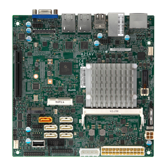
• Product safety info: http://www.supermicro.com/about/policies/safety_information.cfm • If you have any questions, please contact our support team at: support@supermicro.com This manual may be periodically updated without notice. Please check the Supermicro website for possible updates to the manual revision level. - Page 8 Super X11SAA/A2SAV/-V/-2C-L/-2C-LV/-L/-LV User's Manual Figure 1-1. A2SAV/-V/-2C-L/-2C-LV/-L/-LV Motherboard Image Note: All graphics shown in this manual were based upon the latest PCB revision available at the time of publication of the manual. The motherboard you received may or may not look exactly the same as the graphics shown in this manual.
- Page 9 Chapter 1: Introduction Figure 1-2. A2SAV/-V/-2C-L/-2C-LV/-L/-LV Motherboard Layout (not drawn to scale) AUDIO JPL2 JPL1 JPAC1:AUDIO 1-2:ENABLE 2-3:DISABLE USB0/1 HDMI/DP EDP1 LAN2 LAN1 JPL1: LAN1 1-2:ENABLE COM1 2-3:DISABLE JPL2: LAN2 USB2/3(3.0) 1-2:ENABLE 2-3:DISABLE USB8/9 M2_SRW3 FAN1 BAR CODE A2SAV REV:1.02 DESIGNED IN USA JPME2 SRW2...
-
Page 10: Quick Reference
Super X11SAA/A2SAV/-V/-2C-L/-2C-LV/-L/-LV User's Manual Quick Reference COM1 JPL2 USB2/3 (3.0) JPL1 USB8/9 LAN2 USB0/1 HDMI/DP LAN1 AUDIO FP AUDIO JPL2 JPL1 JPAC1:AUDIO 1-2:ENABLE EDP1 2-3:DISABLE USB0/1 HDMI/DP JPAC1 EDP1 LAN2 LAN1 JPL1: LAN1 1-2:ENABLE COM1 2-3:DISABLE JPL2: LAN2 USB2/3(3.0) 1-2:ENABLE... -
Page 11: Quick Reference Table
Chapter 1: Introduction Quick Reference Table Jumper Description Default Setting JBT1 CMOS Clear Open: Normal, Short: Clear CMOS C1/JI SMB to PCI-E Slots Enable/Disable Pins 1-2 (Enabled) JPAC1 Audio Enable Pins 1-2 (Enabled) JPL1 LAN1 Enable/Disable Pins 1-2 (Enabled) JPL2 LAN2 Enable/Disable Pins 1-2 (Enabled) JPME2... - Page 12 Super X11SAA/A2SAV/-V/-2C-L/-2C-LV/-L/-LV User's Manual Connector Description SLOT1 CPU PCI-E 2.0 x2 (IN x8) Slot SRW1/SRW2 m-PCIE Mounting Screws (not available on -L/-LV) USB0/1 Back panel USB 2.0 Port USB2/3 Back panel USB 3.0 Port USB4 USB 2.0 Type A Header (not avaiable on -L/-LV) USB5, USB6/7, USB8/9 Front Accessible USB 2.0 Headers (USB5 and USB6/7 not available on -L/-LV)
-
Page 13: Motherboard Features
One (1) mSATA/mini PCIE Slot (Mux with I-SATA1) (not available on the -L/-LV) Network • Intel® i210 Gigabit Ethernet Controller Graphics • Intel HD Graphics 505 for X11SAA and 500 for A2SAV/-V/-L/-LV I/O Devices • One (1) Fast UART 16550 port on the I/O back panel in RJ45 connector • Serial Port/Header •... - Page 14 Super X11SAA/A2SAV/-V/-2C-L/-2C-LV/-L/-LV User's Manual Motherboard Features BIOS • 128 Mb SPI AMI BIOS SM Flash UEFI BIOS ® • ACPI 3.0, SMBIOS 2.7, BIOS Rescue hotkey, RTC Power Management • ACPI Power Management (S3, S4, S5) • Main switch override mechanism •...
- Page 15 DDI1 DP connector For Booting up, should DDR3L non ECC SKU eDP switch pop in Channe0 EDP connector DUAL CHANNEL Non-ECC-SODIMM0 (X11SAA/A2SAV/-2C-L/-L only) DDR3L 1867 MHz MAX. 8G SO-DIMM SUPPORTED VGA connector REALTEK FST_SPI High Definition FLASH FRONT AUDIO Audio...
-
Page 16: Processor Overview
• Display port, HDMI, VGA or eDP (X11SAA/A2SAV/-2C-L/-L/ only) connections 1.3 Special Features This section describes the health monitoring features of the X11SAA/A2SAV/-V/-2C-L/-2C- LV/-L/-LV motherboard. The motherboard has an onboard System Hardware Monitor chip that supports system health monitoring. Recovery from AC Power Loss The Basic I/O System (BIOS) provides a setting that determines how the system will respond when AC power is lost and then restored to the system. -
Page 17: Acpi Features
Chapter 1: Introduction 1.4 ACPI Features ACPI stands for Advanced Configuration and Power Interface. The ACPI specification defines a flexible and abstract hardware interface that provides a standard way to integrate power management features throughout a computer system including its hardware, operating system and application software. -
Page 18: Chapter 2 Installation
Super X11SAA/A2SAV/-V/-2C-L/-2C-LV/-L/-LV User's Manual Chapter 2 Installation 2.1 Static-Sensitive Devices Electrostatic Discharge (ESD) can damage electronic com ponents. To prevent damage to your motherboard, it is important to handle it very carefully. The following measures are generally sufficient to protect your equipment from ESD. -
Page 19: Motherboard Installation
Chapter 2: Installation 2.2 Motherboard Installation All motherboards have standard mounting holes to fit different types of chassis. Make sure that the locations of all the mounting holes for both the motherboard and the chassis match. Although a chassis may have both plastic and metal mounting fasteners, metal ones are highly recommended because they ground the motherboard to the chassis. -
Page 20: Installing The Motherboard
Super X11SAA/A2SAV/-V/-2C-L/-2C-LV/-L/-LV User's Manual Installing the Motherboard 1. Install the I/O shield into the back of the chassis. 2. Locate the mounting holes on the motherboard. See the previous page for the location. 3. Locate the matching mounting holes on the chassis. Align the mounting holes on the motherboard against the mounting holes on the chassis. -
Page 21: Memory Support And Installation
Note: Check the Supermicro website for recommended memory modules. Important: Exercise extreme care when installing or removing DIMM modules to pre- vent any possible damage. Memory Support The X11SAA/A2SAV/-V/-2C-L/-2C-LV/-L/-LV supports up to 8GB of DDR3L Non-ECC SO- DIMM memory at 1867MHz in one horizontal slot. AUDIO JPL1... -
Page 22: So-Dimm Installation
Super X11SAA/A2SAV/-V/-2C-L/-2C-LV/-L/-LV User's Manual SO-DIMM Installation 1. Position the SO-DIMM module's bottom key so it aligns with the receptive point on the slot. Align 2. Insert the SO-DIMM module vertically at about a 45 degree angle. Press down until the module locks into place. -
Page 23: Rear I/O Ports
Chapter 2: Installation 2.4 Rear I/O Ports See Figure 2-2 below for the locations and descriptions of the various I/O ports on the rear of the motherboard. AUDIO JPL1 JPL2 JPAC1:AUDIO 1-2:ENABLE 2-3:DISABLE USB0/1 HDMI/DP EDP1 LAN2 LAN1 JPL1: LAN1 1-2:ENABLE COM1 2-3:DISABLE... - Page 24 Super X11SAA/A2SAV/-V/-2C-L/-2C-LV/-L/-LV User's Manual VGA Port The onboard VGA port is located next to LAN Port 2 on the I/O back panel. Use this connection for VGA display. HDMI Port The HDMI (High-Definition Multimedia Interface) port is used to display both high definition video and digital sound through an HDMI-capable display, using the same (HDMI) cable.
- Page 25 Chapter 2: Installation Universal Serial Bus (USB) Ports There is one USB 2.0 port (USB0/1) and one USB 3.0 port (USB2/3) located on the I/O back panel. The motherboard also has three front access USB 2.0 headers (USB5, USB6/7, and USB8/9).
- Page 26 A2SAV AUDIO JPL2 REV:1.02 Super X11SAA/A2SAV/-V/-2C-L/-2C-LV/-L/-LV User's Manual DESIGNED IN USA JPAC1:AUDIO 1-2:ENABLE 2-3:DISABLE JPME2 SRW2 EDP1 Serial Ports There is one COM port (COM1) on the I/O back panel via RJ45 and two COM headers (COM2, M2_SRW3 COM3) on the motherboard. COM2 supports RS-232 and COM3 supports RS-485 only.
- Page 27 Chapter 2: Installation LAN Ports Two LAN ports (LAN1 and LAN2) are located on the I/O back panel. These ports accept RJ45 type cables. 1. LAN1 2. LAN2 AUDIO JPL1 JPL2 JPAC1:AUDIO 1-2:ENABLE USB0/1 HDMI/DP 2-3:DISABLE EDP1 LAN2 LAN1 JPL1: LAN1 1-2:ENABLE COM1...
-
Page 28: Front Control Panel
JF1 contains header pins for various buttons and indicators that are normally located on a control panel at the front of the chassis. These connectors are designed specifically for use with Supermicro chassis. See the figure below for the descriptions of the front control panel buttons and LED indicators. - Page 29 Chapter 2: Installation Power LED The Power LED connection is located on pins 15 and 16 of JF1. See the table below for pin definitions. Power LED Pin Definitions (JF1) Pins Definition +3.3V Power LED Active HDD LED The HDD LED connection is located on pins 13 and 14 of JF1. Attach a cable here to indicate the status of HDD-related activities, including IDE and SATA activities.
- Page 30 Super X11SAA/A2SAV/-V/-2C-L/-2C-LV/-L/-LV User's Manual Reset Button The Reset Button connection is located on pins 3 and 4 of JF1. Attach it to a hardware reset switch on the computer case to reset the system. See the table below for pin definitions.
- Page 31 Chapter 2: Installation NMI Button The non-maskable interrupt button header is located on pins 19 and 20. See the table below for pin definitions. NMI Button Pin Definitions (JF1) Pins Definition Control Ground Fan Fail Connect an LED cable to Fan Fail connections on pins 7 and 8 of JF1 to provide warnings for chassis overheat/fan failure.
-
Page 32: Connectors
Super X11SAA/A2SAV/-V/-2C-L/-2C-LV/-L/-LV User's Manual 2.6 Connectors Power Connections Main ATX Power Supply Connector The primary 24-pin ATX power connector (JPW1) is used to provide power to the motherboard. The 4-pin 12V DC PWR connector (JPV1) can also be used as an optional power source when ATX power supply is not available. - Page 33 Chapter 2: Installation Secondary Power Connector JPV1 the 12V DC power connector that provides alternative single power source for special enclosure when the 24-pin ATX power is not in use. +12V 4-pin Power Pin Definitions Pin# Definition 1 - 2 Ground 3 - 4 +12V...
-
Page 34: Headers
Super X11SAA/A2SAV/-V/-2C-L/-2C-LV/-L/-LV User's Manual Headers Fan Headers There are two 4-pin fan headers on the motherboard. Pins 1-3 are backward compatible with traditional 3-pin fans. The onboard fan speeds are controlled by Thermal Management (via Hardware Monitoring) in the BIOS. When using Thermal Management setting, please use all 3-pin fans or all 4-pin fans. - Page 35 Chapter 2: Installation Disk-On-Module Power Connector The Disk-On-Module (DOM) power connector at JSD1 provides 5V power to a solid-state DOM storage device connected to one of the SATA ports. See the table below for pin definitions. DOM Power Pin Definitions Pin# Definition Ground...
- Page 36 Super X11SAA/A2SAV/-V/-2C-L/-2C-LV/-L/-LV User's Manual TPM Header The JTPM1 header is used to connect a Trusted Platform Module (TPM), which is available from a third-party vendor. A TPM is a security device that supports encryption and authentication in hard drives. It enables the motherboard to deny access if the TPM associated with the hard drive is not installed in the system.
- Page 37 Chapter 2: Installation General Purpose I/O Header The JGP1 header is a general purpose I/O on a pin header. See the table below for pin definitions. GPIO Header Pin Definitions Pin# Definition Pin# Definition P3V3_STBY GPIO Memory Address Table Pin Definitions Pin# SoC GPIO # Memory Address...
- Page 38 Super X11SAA/A2SAV/-V/-2C-L/-2C-LV/-L/-LV User's Manual Front Panel Audio Header The 10-pin audio header at AUDIO FP allows you to use the onboard sound for audio playback. Connect an audio cable to this header to use this feature. See the table below for pin definitions for the header.
- Page 39 SATA Ports The X11SAA/A2SAV/-V/-2C-L/-2C-LV/-L/-LV has two SATA 3.0 ports (I-SATA0/1) that are supported by the Intel SoC processor. The X11SAA/A2SAV/-V motherboard also offers four more SATA 3.0 ports (M-SATA0/3) that are supported by the Marvell 88SE9230 controller (with RAID 0, 1, 10 support). See pages 86-90 for instructions on how to set the RAID level.
- Page 40 Super X11SAA/A2SAV/-V/-2C-L/-2C-LV/-L/-LV User's Manual Mini PCI-E Slot The Mini PCI-E slot is used to install a compatible Mini PCI-E device. The slot supports mSATA and is Mux with I-SATA1. The mSATA feature leverages the speed and reliability of the SATA interface to provide a high performance, cost-effective storage solution for smaller devices like notebooks and netbooks.
- Page 41 Chapter 2: Installation Embedded DisplayPort (EDP) The EDP header is used to connect an embedded display LED or LCD panel. EDP is a companion standard to the DispalyPort interface designed for embedded display applications, including PCs, tablets, netbooks and all-in-one desktop PCs. Embedded DisplayPort Pin Definitions Pin#...
-
Page 42: Jumper Settings
Super X11SAA/A2SAV/-V/-2C-L/-2C-LV/-L/-LV User's Manual 2.7 Jumper Settings How Jumpers Work To modify the operation of the motherboard, jumpers can be used to choose between optional settings. Jumpers create shorts between two pins to change the function of the connector. Pin 1 is identified with a square solder pad on the printed circuit board. See the diagram at right for an example of jumping pins 1 and 2. - Page 43 Chapter 2: Installation Front panel Audio Enable JPAC1 allows you to enable or disable front panel audio support. The default setting is Enabled. See the table below for jumper settings. Audio Enable/Disable Jumper Settings Jumper Setting Definition Pins 1-2 Enabled Pins 2-3 Disabled LAN Port Enable/Disable...
- Page 44 Super X11SAA/A2SAV/-V/-2C-L/-2C-LV/-L/-LV User's Manual Watch Dog JWD1 controls the Watch Dog function. Watch Dog is a monitor that can reboot the system when a software application hangs. Jumping pins 1-2 will cause Watch Dog to reset the system if an application hangs. Jumping pins 2-3 will generate a non-maskable interrupt signal for the application that hangs.
- Page 45 Chapter 2: Installation Manufacturing Mode Select Close pins 2-3 on JPME2 to bypass SPI flash security and force the system to use the Manufacturing Mode, which will allow you to flash the system firmware from a host server to modify system settings. See the table below for jumper settings. Manufacturing Mode Jumper Settings Jumper Setting...
-
Page 46: Led Indicators
Super X11SAA/A2SAV/-V/-2C-L/-2C-LV/-L/-LV User's Manual 2.8 LED Indicators LAN1/2 LEDs The Ethernet ports (located beside the VGA port) have two LEDs. On each port, one LED indicates activity when flashing while the other LED may be green, amber or off to indicate the speed of the connection. - Page 47 Chapter 2: Installation Power LED LED2 is the power LED. When this LED is lit, it means power is present on the motherboard. Be sure to turn off the system and unplug the power cord(s) before removing or installing components. LED Indicator LED Color Definition...
-
Page 48: Chapter 3 Troubleshooting
Super X11SAA/A2SAV/-V/-2C-L/-2C-LV/-L/-LV User's Manual Chapter 3 Troubleshooting 3.1 Troubleshooting Procedures Use the following procedures to troubleshoot your system. If you have followed all of the procedures below and still need assistance, refer to the ‘Technical Support Procedures’ and/ or ‘Returning Merchandise for Service’ section(s) in this chapter. Always disconnect the AC power cord before adding, changing or installing any non hot-swap hardware components. -
Page 49: No Video
Chapter 3: Troubleshooting No Video 1. If the power is on but you have no video, remove all the add-on cards and cables. 2. Use the speaker to determine if any beep codes exist. Refer to Appendix A for details on beep codes. -
Page 50: Losing The System's Setup Configuration
2. Memory support: Make sure that the memory modules are supported by testing the modules using memtest86 or a similar utility. Note: Refer to the product page on our website at http:\\www.supermicro.com for memory support and updates. 3. HDD support: Make sure that all hard disk drives (HDDs) work properly. Replace the bad HDDs with good ones. - Page 51 Chapter 3: Troubleshooting 3. Using the minimum configuration for troubleshooting: Remove all unnecessary components (starting with add-on cards first), and use the minimum configuration (but with a CPU and a memory module installed) to identify the trouble areas. Refer to the steps listed in Section A above for proper troubleshooting procedures.
-
Page 52: Technical Support Procedures
Super X11SAA/A2SAV/-V/-2C-L/-2C-LV/-L/-LV User's Manual 3.2 Technical Support Procedures Before contacting Technical Support, please take the following steps. Also, note that as a motherboard manufacturer, we do not sell directly to end-users, so it is best to first check with your distributor or reseller for troubleshooting services. They should know of any possible problem(s) with the specific system configuration that was sold to you. -
Page 53: Frequently Asked Questions
Updated BIOS files are located on our website at http://www. supermicro.com. Please check our BIOS warning message and the information on how to update your BIOS on our website. Select your motherboard model and download the BIOS file to your computer. -
Page 54: Battery Removal And Installation
Super X11SAA/A2SAV/-V/-2C-L/-2C-LV/-L/-LV User's Manual 3.4 Battery Removal and Installation Battery Removal To remove the onboard battery, follow the steps below: 1. Power off your system and unplug your power cable. 2. Locate the onboard battery as shown below. 3. Using a tool such as a pen or a small screwdriver, push the battery lock outwards to unlock it. -
Page 55: Returning Merchandise For Service
Shipping and handling charges will be applied for all orders that must be mailed when service is complete. For faster service, RMA authorizations may be requested online (http://www.supermicro.com/ support/rma/). This warranty only covers normal consumer use and does not cover damages incurred in shipping or from failure due to the alteration, misuse, abuse or improper maintenance of products. -
Page 56: Chapter 4 Uefi Bios
Super X11SAA/A2SAV/-V/-2C-L/-2C-LV/-L/-LV User's Manual Chapter 4 UEFI BIOS 4.1 Introduction This chapter describes the AMIBIOS™ Setup utility for the motherboard. The BIOS is stored on a chip and can be easily upgraded using a flash program. Note: Due to periodic changes to the BIOS, some settings may have been added or deleted and might not yet be recorded in this manual. -
Page 57: Main Setup
The date must be entered in MM/DD/YYYY format. The time is entered in HH:MM:SS format. Note: The time is in the 24-hour format. For example, 5:30 P.M. appears as 17:30:00. Supermicro X11SAA BIOS Version Build Date Memory Information Total Memory: This displays the total size of memory available in the system. - Page 58 Super X11SAA/A2SAV/-V/-2C-L/-2C-LV/-L/-LV User's Manual MRC Version TXE FW...
-
Page 59: Advanced Setup Configurations
Chapter 4: BIOS 4.3 Advanced Setup Configurations Use the arrow keys to select Advanced setup and press <Enter> to access the submenu items: Warning: Take caution when changing the Advanced settings. An incorrect value, a very high DRAM frequency or an incorrect BIOS timing setting may cause the system to malfunction. When this occurs, restore the setting to the manufacture default setting. - Page 60 Super X11SAA/A2SAV/-V/-2C-L/-2C-LV/-L/-LV User's Manual Wait For "F1" If Error This feature forces the system to wait until the 'F1' key is pressed if an error occurs. The options are Disabled and Enabled. INT19 Capture Trap Response Interrupt 19 is the software interrupt that handles the boot disk function. When this item is set to Immediate, the ROM BIOS of the host adaptors will "capture"...
- Page 61 Chapter 4: BIOS CPU Configuration The following CPU information will display: • Displays the CPU model • CPU Signature • Microcode Patch • Max CPU Speed • Min CPU Speed • Processor Cores • Intel HT Technology • Intel VT-x Technology •...
- Page 62 Super X11SAA/A2SAV/-V/-2C-L/-2C-LV/-L/-LV User's Manual Power Limit 1 Enable Use this feature to set the power limit for the CPU. The options are Disable and Enable. Power Limit 1 Power Limit 1 Clamp Mode Use this feature to set the PL1 clamp bit. The options are Disable and Enable.
- Page 63 Chapter 4: BIOS P-STATE Coordination This feature allows the user to change the P-State (Power-Performance State) coordination type. P-State is also known as "SpeedStep" for Intel processors. Select HW_ALL to change the P-State coordination type for hardware components only. Select SW_ALL to change the P-State coordination type for all software installed in the system.
- Page 64 Super X11SAA/A2SAV/-V/-2C-L/-2C-LV/-L/-LV User's Manual Primary Display Use this feature to select the primary video display. The options are IGD and PCIe. RC6 (Render Standby) Select Enabled to enable render standby support. The options are Disabled and Enabled. GTT Size Use this feature to set the memory size to be used by the graphics translation table (GTT).
- Page 65 Chapter 4: BIOS South Bridge The following South Bridge information will be displayed: HD Audio Configuration HD-Audio Support Use this feature to enable high-definition audio support. The options are Enable and Disable. PCI Express Configuration CPU SLOT1 PCI-E 2.0 X2 (IN X8) ASPM Use this item to set the Active State Power Management (ASPM) level for a PCI-E de- vice.
- Page 66 Super X11SAA/A2SAV/-V/-2C-L/-2C-LV/-L/-LV User's Manual USB Configuration USB3.0 Support Select Enable for USB 3.0 support. The options are Enable and Disable. XHCI Pre-Boot Driver Select Enabled to enable XHCI (Extensible Host Controller Interface) support on a pre-boot drive specified by the user. The options are Enabled and Disabled.
- Page 67 Chapter 4: BIOS SATA Port Hot Plug This feature designates the SATA port specified for hot plugging. Set this item to Enabled for hot-plugging support, which will allow the user to replace a SATA disk drive without shutting down the system. The options are Enabled and Disabled. Spin Up Device When the value of an edge detect or the value of an image binary (pixel) of a device is from 0 to 1, select Enabled to allow the PCH to start a COMRESET initialization sequence on this...
- Page 68 Super X11SAA/A2SAV/-V/-2C-L/-2C-LV/-L/-LV User's Manual TPM Enabled Status TPM Active Status TPM Owner Status ACPI Settings ACPI Sleep State Use this feature to select which sleep state mode the system will enter when the Suspend button is pressed. The options are Suspend Disabled and S3 (Suspend to RAM).
- Page 69 Chapter 4: BIOS Serial Port 2 Configuration Serial Port 2 Select Enabled to enable the onboard serial port specified by the user. The options are Disabled and Enabled Device Settings This item displays the base I/O port address and the Interrupt Request address of a serial port specified by the user.
- Page 70 Super X11SAA/A2SAV/-V/-2C-L/-2C-LV/-L/-LV User's Manual Fan Speed Control Mode Use this feature to select the fan speed control mode. The options are Standard and Full Speed. • Fan2 Speed • Pan1 Speed • VCORE • VDIMM • VBAT Serial Port Console Redirection ...
- Page 71 Chapter 4: BIOS COM1 Parity A parity bit can be sent along with regular data bits to detect data transmission errors. Select Even if the parity bit is set to 0, and the number of 1's in data bits is even. Select Odd if the parity bit is set to 0, and the number of 1's in data bits is odd.
- Page 72 Super X11SAA/A2SAV/-V/-2C-L/-2C-LV/-L/-LV User's Manual COM1 Redirection After BIOS POST Use this feature to enable or disable legacy console redirection after BIOS POST. When set to Bootloader, legacy console redirection is disabled before booting the OS. When set to Always Enable, legacy console redirection remains enabled when booting the OS. The options are Always Enable and Bootloader.
- Page 73 Chapter 4: BIOS COM2 Stop Bits A stop bit indicates the end of a serial data packet. Select 1 Stop Bit for standard serial data communication. Select 2 Stop Bits if slower devices are used. The options are 1 and 2. COM2 Flow Control Use this feature to set the flow control for Console Redirection to prevent data loss caused by buffer overflow.
- Page 74 Super X11SAA/A2SAV/-V/-2C-L/-2C-LV/-L/-LV User's Manual EMS (Emergency Management Services) Console Redirection Select Enabled to use a COM port selected by the user for EMS Console Redirection. The options are Enabled and Disabled. *If the item above set to Enabled, the following items will become available for user's configuration: EMS Console Redirection Settings...
- Page 75 Chapter 4: BIOS PCIe/PCI/PnP Configuration PCI Bus Driver Version A5.01.08 PCI Devices Common Settings: Above 4G Decoding Select Enabled for 64-bit devices to be decoded above the 4GB address space If 64bit PCI decoding is supported by the system. The options are Disabled and Enabled. CPU SLOT1 PCI-E 2.0 X2 (INX8) OPROM Use this feature to select the type of firmware to be loaded for the device installed on this slot.
- Page 76 Super X11SAA/A2SAV/-V/-2C-L/-2C-LV/-L/-LV User's Manual Media detect count Use this option to specify the number of times media will be checked. Press "+" or "-" on your keyboard to change the value. The default setting is 1. iSCSi Configuration iSCSI Initiator Name This feature allows the user to enter the unique name of the iSCSI Initiator in IQN format.
- Page 77 Chapter 4: BIOS Device Name This item displays the adapter device name. Chip Type This item displays the network adapter chipset name. PCI Device ID This item displays the device ID number. PCI Address This item displays the PCI address for this computer. PCI addresses are three two-digit hexadecimal numbers.
- Page 78 Super X11SAA/A2SAV/-V/-2C-L/-2C-LV/-L/-LV User's Manual UEFI Driver This item displays the UEFI driver version. Adapter PBA This item displays the Processor Bus Adapter (PBA) model number. The PBA number is a nine digit number (i.e., 010B00-000) located near the serial number.
-
Page 79: Security
Chapter 4: BIOS 4.4 Security This menu allows the user to configure Security settings. Password Check Use this feature to determine when a password entry is required. Select Setup to require the password only when entering setup. Select Always to require the password when entering setup and at each bootup. - Page 80 Super X11SAA/A2SAV/-V/-2C-L/-2C-LV/-L/-LV User's Manual Secure Boot Mode This feature allows the user to select the desired secure boot mode for the system. The options are Standard and Customized. If Secure Boot Mode is set to Customized, Key Management features will be available for configuration: ...
- Page 81 Chapter 4: BIOS Authorized Signatures Set New Key Select Yes to load the database from the manufacturer's defaults. Select No to load the DB from a file. The options are Yes and No. Append Key Select Yes to add the database from the manufacturer's defaults to the existing DB. Select No to load the DB from a file.
-
Page 82: Boot
Super X11SAA/A2SAV/-V/-2C-L/-2C-LV/-L/-LV User's Manual 4.5 Boot Use this feature to configure Boot Settings: Fixed Boot Order Priorities This option prioritizes the order of bootable devices that the system can boot from. Press <Enter> on each entry from top to bottom to select devices. - Page 83 Chapter 4: BIOS UEFI Application Boot Priorities This feature allows the user to specify which UEFI devices are boot devices. • UEFI Boot Order #1 UEFI USB Key Drive BBS Priorities This feature allows the user to specify which UEFI USB Key drive devices are boot devices. This feature is displayed when a storage device is detected.
-
Page 84: Save & Exit
Super X11SAA/A2SAV/-V/-2C-L/-2C-LV/-L/-LV User's Manual 4.6 Save & Exit Select the Exit tab from the BIOS setup utility screen to enter the Exit BIOS Setup screen. Save Options Discard Changes and Exit Select this option to quit the BIOS Setup without making any permanent changes to the system configuration, and reboot the computer. - Page 85 Chapter 4: BIOS Default Options Restore Defaults To set this feature, select Restore Defaults from the Exit menu and press <Enter>. These are factory settings designed for maximum system performance but not for maximum stability. Save as User Defaults To set this feature, select Save as User Defaults from the Exit menu and press <Enter>. This enables the user to save any changes to the BIOS setup for future use.
-
Page 86: Raid Level Settings
Preparation 1. A FAT32 USB Drive. 2. Download "ui64.efi" from the Supermicro website and then copy it to the USB drive. 3. After booting up the system, press F11 to show the boot menu and select the first choice. This will take you to the EFI shell. - Page 87 Chapter 4: BIOS RAID Level Setup 1. At the Shell prompt, type fs0: to map the USB flash drive with the Marvell BIOS Utility. 2. Type ui64.efi. Then you will see the Marvell BIOS Setup screen below.
- Page 88 Super X11SAA/A2SAV/-V/-2C-L/-2C-LV/-L/-LV User's Manual 3. Select the first option and press Enter. Then press Enter after you see Configuration Wizard highligthed in green. 4. Highlight the hard drives that you want to set the RAID level. Highlighted drives will have...
- Page 89 Chapter 4: BIOS 5. Select the drive and press Enter. Then select the RAID level in the box on the right. After making your selections, press F10 to save and exit. Reboot the system for the changes to take effect.
-
Page 90: Appendix A Bios Codes
Super X11SAA/A2SAV/-V/-2C-L/-2C-LV/-L/-LV User's Manual Appendix A BIOS Codes A.1 BIOS Error POST (Beep) Codes During the POST (Power-On Self-Test) routines, which are performed each time the system is powered on, errors may occur. Non-fatal errors are those which, in most cases, allow the system to continue the boot up procedure. -
Page 91: Additional Bios Post Codes
When BIOS performs the Power On Self Test, it writes checkpoint codes to I/O port 0080h. If the computer cannot complete the boot process, a diagnostic card can be attached to the computer to read I/O port 0080h (Supermicro p/n AOC-LPC80-20). For information on AMI updates, please refer to http://www.ami.com/products/. -
Page 92: Appendix B Software Installation
Appendix B Software Installation B.1 Installing Software Programs The Supermicro website that contains drivers and utilities for your system is at https://www. supermicro.com/wftp/driver/. Some of these must be installed, such as the chipset driver. After accessing the website, go into the CDR_Images directory and locate the ISO file for your motherboard. -
Page 93: Superdoctor ® 5
SATA settings back to your original settings. B.2 SuperDoctor ® The Supermicro SuperDoctor 5 is a hardware monitoring program that functions in a command-line or web-based interface in Windows and Linux operating systems. The program monitors system health information such as CPU temperature, system voltages, system power consumption, fan speed, and provides alerts via email or Simple Network Management Protocol (SNMP). -
Page 94: Appendix C Standardized Warning Statements
The following statements are industry standard warnings, provided to warn the user of situations which have the potential for bodily injury. Should you have questions or experience difficulty, contact Supermicro's Technical Support department for assistance. Only certified technicians should attempt to install or configure components. - Page 95 Appendix C: Warning Statements Attention Danger d'explosion si la pile n'est pas remplacée correctement. Ne la remplacer que par une pile de type semblable ou équivalent, recommandée par le fabricant. Jeter les piles usagées conformément aux instructions du fabricant. ¡Advertencia! Existe peligro de explosión si la batería se reemplaza de manera incorrecta.
-
Page 96: Product Disposal
Super X11SAA/A2SAV/-V/-2C-L/-2C-LV/-L/-LV User's Manual Product Disposal Warning! Ultimate disposal of this product should be handled according to all national laws and regulations. 製品の廃棄 この製品を廃棄処分する場合、 国の関係する全ての法律 ・ 条例に従い処理する必要があります。 警告 本产品的废弃处理应根据所有国家的法律和规章进行。 警告 本產品的廢棄處理應根據所有國家的法律和規章進行。 Warnung Die Entsorgung dieses Produkts sollte gemäß allen Bestimmungen und Gesetzen des Landes erfolgen. -
Page 97: Appendix D Uefi Bios Recovery
Warning: Do not upgrade the BIOS unless your system has a BIOS-related issue. Flashing the wrong BIOS can cause irreparable damage to the system. In no event shall Supermicro be liable for direct, indirect, special, incidental, or consequential damages arising from a BIOS update. - Page 98 Super X11SAA/A2SAV/-V/-2C-L/-2C-LV/-L/-LV User's Manual To perform UEFI BIOS recovery using a USB-attached device, follow the instructions below. 1. Using a different system, copy the "Super.ROM" binary image file into the disc Root "\" Directory of a USB device or a writeable CD/DVD.
- Page 99 Appendix D: UEFI BIOS Recovery 4. After locating the new BIOS binary image, the system will enter the BIOS Recovery menu as shown below. Note: At this point, you may decide if you want to start the BIOS recovery. If you decide to proceed with BIOS recovery, follow the procedures below.
- Page 100 Super X11SAA/A2SAV/-V/-2C-L/-2C-LV/-L/-LV User's Manual 6. After the BIOS recovery process has completed, press any key to reboot the system. 7. Using a different system, extract the BIOS package into a bootable USB flash drive. 8. When a DOS prompt appears, enter FLASH.BAT BIOSname.### at the prompt.