Table of Contents
Advertisement
Quick Links
EB 2626-1 EN
Translation of original instructions
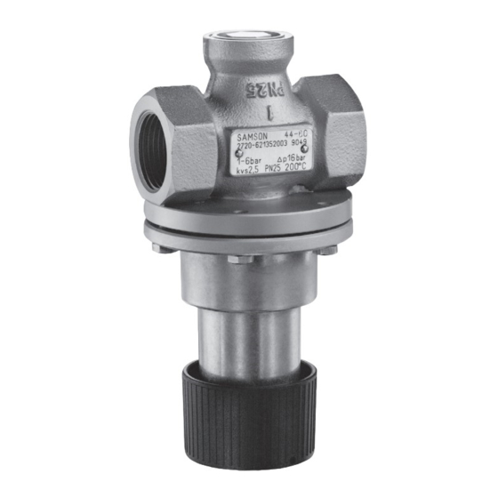
Type 44-0 B Steam Pressure Reducing Valve,
Type 44-1 B Pressure Reducing Valve,
body with screwed ends, red brass
body with screwed ends, stainless steel
Type 44-0 B and Type 44-1 B Pressure Reducing Valves
Self-operated Pressure Regulators
Edition February 2022
Advertisement
Table of Contents

Related Manuals for Samson 44-0 B


Summary of Contents for Samson 44-0 B
- Page 1 EB 2626-1 EN Translation of original instructions Type 44-0 B Steam Pressure Reducing Valve, Type 44-1 B Pressure Reducing Valve, body with screwed ends, red brass body with screwed ends, stainless steel Type 44-0 B and Type 44-1 B Pressure Reducing Valves Self-operated Pressure Regulators Edition February 2022...
- Page 2 Note on these mounting and operating instructions These mounting and operating instructions assist you in mounting and operating the device safely. The instructions are binding for handling SAMSON devices. The images shown in these instructions are for illustration purposes only. The actual product may vary.
-
Page 3: Table Of Contents
Contents Safety instructions and measures ..............1-1 Notes on possible severe personal injury ............1-4 Notes on possible personal injury ..............1-4 Notes on possible property damage .............1-6 Markings on the device ................2-1 Nameplates ....................2-1 Location of the nameplates ................2-2 Material identification number ..............2-2 Design and principle of operation ...............3-1 Additional fittings ..................3-3 Technical data ....................3-4... - Page 4 Decommissioning ..................10-1 Removal ....................11-1 11.1 Removing the regulator from the pipeline ............11-1 11.2 Removing the actuator from the valve ............11-1 Repairs ....................12-1 12.1 Returning devices to SAMSON ..............12-1 Disposal ....................13-1 Certificates ....................14-1 Annex......................15-1 15.1 Tightening torques ..................15-1 15.2 Lubricant ....................15-1 15.3...
-
Page 5: Safety Instructions And Measures
In case operators intend to use the regulators in other applications or conditions than specified, contact SAMSON. SAMSON does not assume any liability for damage resulting from the failure to use the de- vice for its intended purpose or for damage caused by external forces or any other external factors. - Page 6 Î Check with the plant operator for details on further protective equipment. Revisions and other modifications Revisions, conversions or other modifications of the product are not authorized by SAMSON. They are performed at the user's own risk and may lead to safety hazards, for example. Fur- thermore, the product may no longer meet the requirements for its intended use.
- Page 7 Safety instructions and measures Responsibilities of operating personnel Operating personnel must read and understand these mounting and operating instructions as well as the referenced documents and observe the specified hazard statements, warnings and caution notes. Furthermore, operating personnel must be familiar with the applicable health, safety and accident prevention regulations and comply with them.
-
Page 8: Notes On Possible Severe Personal Injury
WARNING Damage to health relating to the REACH regulation. If a SAMSON device contains a substance which is listed as being a substance of very high concern on the candidate list of the REACH regulation, this circumstance is indi- cated on the SAMSON delivery note. - Page 9 Safety instructions and measures WARNING Risk of burn injuries due to hot or cold components and pipelines. Depending on the process medium, regulator components and pipelines may get very hot or cold and cause burn injuries. Î Allow components and pipelines to cool down or warm up to the ambient tempera- ture.
-
Page 10: Notes On Possible Property Damage
The lubricants to be used depend on the regulator material. Unsuitable lubricants may corrode and damage surfaces. Î Only use lubricants approved by SAMSON. When in doubt, consult SAMSON. Risk of leakage and regulator damage due to excessively high or low tightening torques. - Page 11 Î Keep the regulator and the tools used free from solvents and grease. Î Make sure that only suitable lubricants are used. Note SAMSON's After-sales Service can support you concerning lubricant, tightening torques and tools approved by SAMSON. EB 2626-1 EN...
- Page 12 Safety instructions and measures EB 2626-1 EN...
-
Page 13: Markings On The Device
Markings on the device 2 Markings on the device 2.1 Nameplates Nameplate on red brass body 1 Model number 2 Configuration ID (Var.-ID) and device index 3 Order number or year of manufacture 4 Type designation 5 Valve size/thread size 7 Perm. -
Page 14: Location Of The Nameplates
Markings on the device 2.2 Location of the nameplates 2.3 Material identification number The nameplate of all sizes is affixed to the body (see Fig. 2-2). The material is indicated on the cast body. Specifying the configuration ID, you can con- tact us to find out more details. -
Page 15: Design And Principle Of Operation
Design and principle of operation 3 Design and principle of oper- ation Î See Fig. 3-1 The Type 44-0 B and Type 44-1 B Pressure Reducing Valves consist of a single-seated globe valve with integrated actuator unit. The regulators mainly consist of the valve (1) with seat (3), plug (2) and balancing bellows (6) as well as a spring housing with operat- ing bellows (5), set point spring (7) and set... - Page 16 Design and principle of operation 11 8 Special version Connecting thread G A for a pressure gauge or external control line · Dimensions in mm Stainless steel version Leakage line connection (standard) Valve Actuator housing Set point screw All stainless steel and spheroidal graphite iron versions (DN 40/50) as well as 8 to 20 bar set Type 44-0 B, Type 44-1 B point range: hex socket screw with SW 3 or...
-
Page 17: Additional Fittings
Any impurities carried along by the process medium may impair the proper functioning Strainers of the regulator. We recommend installing a We recommend installing a SAMSON strainer (e.g. SAMSON Type 1 NI) upstream strainer (3) upstream of the valve. It prevents of the pressure reducing valve (u EB 1010). -
Page 18: Technical Data
Design and principle of operation 3.2 Technical data Bypass and shut-off valves We recommend installing a shut-off valve (1) The regulator nameplate provides informa- both upstream of the strainer and down- tion on the regulator version (see the 'Mark- stream of the regulator and installing a by- ings on the device' section). - Page 19 (see Table 3-2). Noise emissions Dimensions and weights SAMSON is unable to make general state- Table 3-4 provides a summary of the dimen- ments about noise emissions. The noise emis- sions and weights. The lengths and heights...
- Page 20 Design and principle of operation Table 3-2: Technical data · All pressures in bar (gauge) Regulator Pressure reducing valve 44-0 B 44-1 B Stainless steel/red brass body Female thread G ½, G ¾, G 1 · ½ NPT, ¾ NPT, 1 NPT Port Stainless steel body Flanges DN 15 and 25 · NPS ½ and 1 Spheroidal graphite iron body Flanges DN 15, 25, 40 and 50 1)
- Page 21 Design and principle of operation Table 3-3: K coefficients and xFZ values · Terms for noise level calculation according to VDMA 24422 (edition 1.89) Body with screwed ends Connection size G ½ · ½ NPT G ¾ · ¾ NPT G 1 · 1 NPT Standard version 1) 1) 1) Type 44-1 B Special version 0.25 · 1.0 · 2.5...
- Page 22 Design and principle of operation Table 3-4: Dimensions in mm/in · Weights in kg/lb – Regulator G/NPT ½ ¾ – – ½ – – – – – G · NPT 1) 2) – – Length L – – – – 1) 3) – – –...
- Page 23 Design and principle of operation Dimensional drawings Body: red brass (DIN version only) Body: stainless steel Ø90 Ø90 Body: spheroidal graphite iron (DIN version 1) Body: stainless steel only) DN 15 and 25 with manual adjuster, DN 40 and 50 as well as 8 to 20 bar set point range with set point screw. Fig. 3-3: Dimensions EB 2626-1 EN...
- Page 24 Design and principle of operation 3-10 EB 2626-1 EN...
-
Page 25: Shipment And On-Site Transport
Report any damage to regulator (e.g. to install it into the pipeline). SAMSON and the forwarding agent Î Leave the regulator in its transport con- (refer to delivery note). tainer or on the pallet to transport it. -
Page 26: Storing The Regulator
Special storage instructions for elastomers Î Avoid long storage times. Elastomer, e.g. O-rings Î Contact SAMSON in case of different Î To keep elastomers in shape and to pre- storage conditions or longer storage vent cracking, do not bend them or hang times. -
Page 27: Installation
(see Fig. 5-1). and are intended as recommendations. Con- Î Make sure the direction of flow matches tact SAMSON if the lengths are significantly the direction indicated by the arrow on shorter than the recommended lengths. the body. -
Page 28: Preparation For Installation
Installation 5.2 Preparation for installation Standard mounting position of Before mounting, make sure the following Type 44-0 B and Type 44-1 B conditions are met: For gases, liquids and steam − The regulator is clean. − The regulator is not damaged. − Install a strainer upstream of the regula- tor. - Page 29 Installation Table 5-1: Inlet and outlet lengths min. min. a x DN b x DN Inlet length Outlet length State of process Valve conditions Inlet length a Outlet length b medium Ma ≤ 0.3 Vapors Ma ≤ 0.3 1) Free of cavitation/w < 3 Liquid Cavitation producing noise/w ≤ 3 No wet steam EB 2626-1 EN...
-
Page 30: Installation
Risk of regulator damage due to the use of 3. Observe the flow direction through the unsuitable tools. valve. The arrow on the valve indicates Î Only use tools approved by SAMSON the direction of flow. (see 'Tools' in Annex). 4. Make sure that the correct gaskets are used. -
Page 31: Testing The Regulator
Flying projectile fragments or the re- gloves. lease of process medium under pressure can cause serious injury or even death. SAMSON regulators are delivered ready for Before working on the regulator: use. To test the regulator functioning before Î Depressurize all plant sections concerned start-up or putting back the regulator into and the regulator. -
Page 32: Pressure Test
Note The plant operator is responsible for NOTICE performing the pressure test. SAMSON's Risk of regulator damage due to incorrect After-sales Service can support you to plan insulation. and perform a pressure test for your plant. -
Page 33: Start-Up
Start-up 6 Start-up WARNING The work described in this section is only to Risk of personal injury due to pressurized be performed by personnel appropriately components and process medium being qualified to carry out such tasks. discharged. Î Do not loosen the control line while the valve is pressurized. -
Page 34: Start-Up And Putting The Device Back Into Operation
Start-up 6.1 Start-up and putting the 6.1.2 Starting up the plant device back into operation when vapors are controlled 1. Depending on the field of application, allow the regulator to cool down or 1. Completely drain and dry steam lines to warm up to reach ambient temperature prevent water hammering. -
Page 35: Operation
Operation 7 Operation 7.1 Adjusting the set point Immediately after completing start-up or Adjust the required set point by turning the placing the regulator back into service (see set point adjuster (8) by hand or the set point the 'Start-up' section), the regulator is ready screw (9) using an Allen key (3 or 5 mm for use. - Page 36 Operation EB 2626-1 EN...
-
Page 37: Malfunctions
Î Remove foreign particles. Foreign particles blocking the Î Replace damaged parts. plug Î Contact SAMSON's After-sales Service. Î Replace the damaged seat and plug. Downstream pressure ex- Seat and plug are worn or leak. Î Contact SAMSON's After-sales Service. - Page 38 Î Change K coefficient, if necessary or install too large a different sized regulator. Downstream pressure Î Contact SAMSON's After-sales Service. hunts Î Reconnect the control line at another point. Pressure tapped at the wrong place (regulator with external Î Do not connect the control line at pipe bends or control line) necks.
-
Page 39: Emergency Action
Malfunctions 8.2 Emergency action Note Contact SAMSON's After-sales Service for Plant operators are responsible for emergen- malfunctions not listed in the table. cy action to be taken in the plant. We recommend removing the regulator from The malfunctions listed in section 8.1 are the pipeline before repairing it. - Page 40 Malfunctions EB 2626-1 EN...
-
Page 41: Servicing
Servicing 9 Servicing WARNING The regulator does not require any mainte- Risk of burn injuries due to hot or cold nance. Nevertheless, it is subject to natural components and pipeline. wear, particularly at the seat, plug and oper- Regulator components and the pipeline may ating diaphragm/bellows. - Page 42 NOTICE Valve body Risk of regulator damage due to the use of 1.1 Body gasket unsuitable tools. 1.2 Seal Î Only use tools approved by SAMSON Plug (see 'Tools' in Annex). Seat Borehole in body for downstream pressure Operating bellows...
- Page 43 Servicing Valve Actuator housing Set point screw All stainless steel and spheroidal graphite iron Type 44-0 B, Type 44-1 B versions (DN 40/50) as well as 8 to 20 bar set Red brass body with screwed ends point range: hex socket screw with SW 3 or SW 5 (spheroidal graphite iron) Fig. 9-1: Functional diagram of Type 44-0 B and Type 44-1 B Pressure Reducing Valves EB 2626-1 EN...
-
Page 44: Preparing The Valve For Service Work
Servicing 9.1 Preparing the valve for 9.3 Service work service work Î Before performing any service work, preparations must be made to the regu- 1. Lay out the necessary material and tools lator (see section 9.1). to have them ready for the service work. Î... -
Page 45: Replacing The Operating Bellows
Servicing 6. Unscrew the seat using a seat wrench if Assembly the seat facing is damaged. 1. Replace the body gasket (1.1) with a new one. Assembly 2. Place the spring housing with spring (7) 1. Screw in the seat using a seat wrench. and operating bellows (5) onto the valve Observe the specified tightening torques body. -
Page 46: Ordering Spare Parts And Operating Supplies
9.4 Ordering spare parts and operating supplies Contact your nearest SAMSON subsidiary or SAMSON's After-sales Service for infor- mation on spare parts, lubricants and tools. Spare parts See Annex for details on spare parts. -
Page 47: Decommissioning
Decommissioning 10 Decommissioning WARNING The work described in this section is only to Risk of personal injury due to pressurized be performed by personnel appropriately components and process medium being qualified to carry out such tasks. discharged. Î Do not loosen the external control line while the valve is pressurized. - Page 48 Decommissioning To decommission the regulator for service work or disassembly, proceed as follows: 1. Close the shut-off valve (1) on the down- stream and upstream side of the regula- tor. 2. Completely drain the pipelines and regu- lator. 3. Depressurize the plant. 4.
-
Page 49: Removal
Removal 11 Removal 11.1 Removing the regulator from the pipeline The work described in this section is only to be performed by personnel appropriately 1. Support the regulator to hold it in place qualified to carry out such tasks. when separated from the pipeline (see the 'Shipment and on-site transport' sec- WARNING tion). - Page 50 Removal 11-2 EB 2626-1 EN...
-
Page 51: Repairs
Defective devices can be returned to does not function at all, it is defective and SAMSON for repair. Proceed as follows to must be repaired or exchanged. return devices to SAMSON: 1. Put the regulator out of operation (see... - Page 52 Repairs 12-2 EB 2626-1 EN...
-
Page 53: Disposal
Disposal 13 Disposal Î Observe local, national and internation- al refuse regulations. Î Do not dispose of components, lubricants and hazardous substances together with your household waste. EB 2626-1 EN 13-1... - Page 54 Disposal 13-2 EB 2626-1 EN...
-
Page 55: Certificates
Certificates 14 Certificates The EU declarations of conformity are included on the next pages: − EU declaration of conformity in compliance with Pressure Equipment Directive 2014/68/EU on page 14-2. EB 2626-1 EN 14-1... - Page 56 Certificates 14-2 EB 2626-1 EN...
- Page 57 Certificates EB 2626-1 EN 14-3...
- Page 58 Certificates 14-4 EB 2626-1 EN...
-
Page 59: Annex
DN 40 and 50/NPS 1½ and 2 Screws (10) – Stopper (11) – 15.2 Lubricant SAMSON's After-sales Service can support you concerning lubricants and sealants ap- proved by SAMSON. 15.3 Tools SAMSON's After-sales Service can support you concerning tools approved by SAMSON. -
Page 60: Spare Parts
Annex 15.4 Spare parts Plug assembly Bellows assembly Pipe Handwheel 340 … 342 O-ring Stopper 344/345 O-ring Body Gasket Seal Retaining washer Threaded seat Shim Seat Spring washer Spring housing Dry bearing Washer Nipple Cap screw Compression spring Hex screw 321 … 324 Set point spring Plug Spindle Reinforcement plate... -
Page 61: After-Sales Service
E-mail address You can reach our after-sales service at aftersalesservice@samsongroup.com. Addresses of SAMSON AG and its subsid- iaries The addresses of SAMSON, its subsidiaries, representatives and service facilities worldwide can be found on our website (u www.samsongroup.com) or in all... - Page 62 Annex 15-4 EB 2626-1 EN...
- Page 66 EB 2626-1 EN SAMSON AKTIENGESELLSCHAFT Weismüllerstraße 3 · 60314 Frankfurt am Main, Germany Phone: +49 69 4009-0 · Fax: +49 69 4009-1507 samson@samsongroup.com · www.samsongroup.com...