
Related Manuals for Samson 42-10


Summary of Contents for Samson 42-10
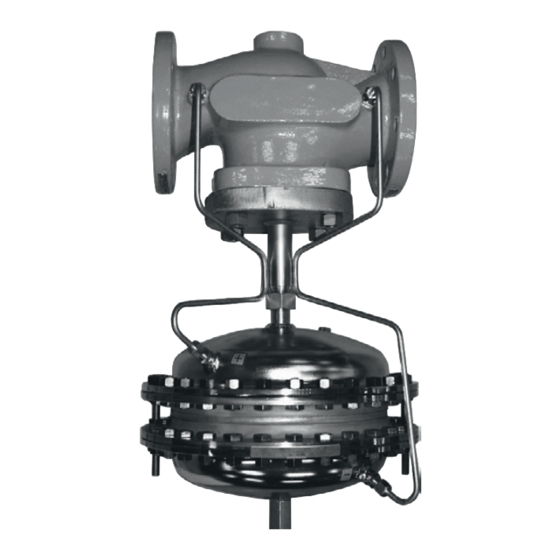
- Page 1 EB 3009 EN Translation of original instructions Type 42-10 RS Check Valve (backflow protection) Self-operated Regulators Edition December 2020...
- Page 2 Note on these mounting and operating instructions These mounting and operating instructions assist you in mounting and operating the device safely. The instructions are binding for handling SAMSON devices. The images shown in these instructions are for illustration purposes only. The actual product may vary.
-
Page 3: Table Of Contents
Contents Safety instructions and measures ..............1-1 Notes on possible severe personal injury ............1-4 Notes on possible personal injury ..............1-5 Notes on possible property damage .............1-7 Markings on the device ................2-1 Valve nameplate ..................2-1 Actuator nameplate ..................2-2 Location of the nameplates ................2-2 2.4 Material identification number ..............2-2 2.4.1... - Page 4 Decommissioning ..................10-1 Removal ....................11-1 11.1 Removing the regulator from the pipeline ............11-1 11.2 Removing the actuator from the valve ............11-1 Repairs ....................12-1 12.1 Returning devices to SAMSON ..............12-1 Disposal ....................13-1 Certificates ....................14-1 Annex......................15-1 15.1 Tightening torques ..................15-1 15.2 Lubricant ....................15-1 15.3...
-
Page 5: Safety Instructions And Measures
In case operators intend to use the regulators in other applications or conditions than specified, contact SAMSON. SAMSON does not assume any liability for damage resulting from the failure to use the de- vice for its intended purpose or for damage caused by external forces or any other external factors. - Page 6 − Safety footwear, ESD (electrostatic discharge) footwear, if necessary Î Check with the plant operator for details on further protective equipment. Revisions and other modifications Revisions, conversions or other modifications of the product are not authorized by SAMSON. They are performed at the user's own risk and may lead to safety hazards, for example. Fur- thermore, the product may no longer meet the requirements for its intended use.
- Page 7 Start-up and shutdown procedures fall within the scope of the operator's duties and, as such, are not part of these mounting and operating instructions. SAMSON is unable to make any statements about these procedures since the operative details (e.g. differential pressures and temperatures) vary in each individual case and are only known to the operator.
-
Page 8: Notes On Possible Severe Personal Injury
Safety instructions and measures Referenced documentation The following documents apply in addition to these mounting and operating instructions: − Mounting and operating instructions for e.g. Type 2 N/NI Strainer u EB 1015 − Data sheets for e.g. Accessories · Differential pressure and flow regulators u T 3095 Type 2 N/NI Strainer e.g. -
Page 9: Notes On Possible Personal Injury
Safety instructions and measures 1.2 Notes on possible personal injury WARNING Risk of personal injury through incorrect operation, use or installation as a result of information on the regulator being illegible. Over time, markings, labels and nameplates on the regulator may become covered with dirt or become illegible in some other way. As a result, hazards may go unno- ticed and the necessary instructions not followed. - Page 10 Î Wear protective clothing, safety gloves and eye protection. Damage to health relating to the REACH regulation. If a SAMSON device contains a substance which is listed as being a substance of very high concern on the candidate list of the REACH regulation, this circumstance is indi- cated on the SAMSON delivery note.
-
Page 11: Notes On Possible Property Damage
The lubricants to be used depend on the regulator material. Unsuitable lubricants may corrode and damage surfaces. Î Only use lubricants approved by SAMSON. When in doubt, consult SAMSON. Risk of leakage and regulator damage due to excessively high or low tightening torques. - Page 12 Î Keep the regulator and the tools used free from solvents and grease. Î Make sure that only suitable lubricants are used. Note SAMSON's After-sales Service can support you concerning lubricant, tightening torques and tools approved by SAMSON. EB 3009 EN...
-
Page 13: Markings On The Device
Markings on the device 2 Markings on the device Several nameplates are affixed to the device. The nameplates are used to identify the sepa- rate regulator components (see section 2.1 and section 2.2). 2.1 Valve nameplate DIN version ANSI version Pressure rating Valve type Perm. differential pressure Set point range or spring Model number with index range 10 Perm. temperature Material number Valve size 11 Body material Order number or date... -
Page 14: Actuator Nameplate
Markings on the device 2.2 Actuator nameplate DIN/ANSI version Actuator area (DIN/ANSI) Pressure rating PN Differential pressure across max. Class (DIN/ANSI) the restriction (DIN/ANSI) Material number and device max. index Valve size (DIN/ANSI) 10 Diaphragm material ID number 8.1 Max. test pressure 11 CE marking Year of manufacture 12 Certification body number Fig. 2-2: Actuator nameplate 2.3 Location of the nameplates... -
Page 15: Design And Principle Of Operation
Design and principle of operation 3 Design and principle of oper- The mounted control lines (14) transmit the upstream and downstream pressures to the ation actuator. Î See Fig. 3-1 and Fig. 3-2 The actuator with two diaphragms (11) The regulator prevents flowback from directly offers increased safety and reliability of connected systems. - Page 16 Design and principle of operation 13.1 11.1 16.1 16.2 10.1 11.2 Fig. 3-1: Functional diagram of regulator, DN 15 to 150/NPS ½ to 6 EB 3009 EN...
- Page 17 Design and principle of operation Legend for Fig. 3-1 and Fig. 3-2 Valve body Set point springs Seat 13.1 Force limiter Plug Control line 8x1 mm Plug stem Spacer bushing including seal Threaded connection for diaphragm actuator Housing bolts (two long bolts opposite each other, DN 15 to 25/NPS ½ to 1 only) Actuator stem 16.1 Top housing bolts Diaphragm stem 16.2 Bottom housing bolts Actuator housing...
-
Page 18: Additional Fittings
Design and principle of operation 3.1 Additional fittings Strainer We recommend installing a SAMSON Î See Fig. 3-3 strainer (2) upstream of the valve. It prevents solid particles in the process medium from Pressure gauges damaging the regulator. Install a pressure gauge (3 and 5) at suitable Î... -
Page 19: Technical Data
(u T 3009). Noise emissions Process medium and scope of application SAMSON is unable to make general state- The Type 42-10 RS Check Valve is used to ments about noise emissions. The noise emis- prevent the backflow protection of a medi- sions depend on the regulator version, plant facilities, process medium and operating − For liquids, gases and vapors... - Page 20 Design and principle of operation Table 3-1: Technical data · Valves · All pressures in bar Type 2421 RS Valve DN 15 to 250/NPS ½ to 10 Valve size Pressure rating PN 16, 25 and 40/Class 150 and 300 Max. constant operating pressure 25 bar/360 psi Max. perm. pressure acting on one side 45 bar/650 psi Leakage class according to IEC 60534-4 Leakage class VI With EPDM diaphragm in 80 °C/175 °F for air, gases and water actuator...
- Page 21 Design and principle of operation Table 3-2: Materials · Material number according to DIN EN Type 2421 RS Valve PN 16, 25 and 40 PN 40 Pressure rating Class 150/300 Class 300 Valve body Cast steel 1.0619 Cast stainless steel 1.4408 Forged stainless steel 1.4571 Seat and plug Stainless steel 1.4404 with EPDM soft seal Plug stem...
- Page 22 Design and principle of operation Dimensions and weights DN 15 to 150/NPS ½ to 6 DN 200 and 250/NPS 8 and 10 ØD ØD Dimensions in mm and weights · DIN version Valve size Length L Height H1 Forged steel – – – Height 1.4571 Other materials Height H...
- Page 23 Design and principle of operation Dimensions and weights Dimensions in inches and weights · ANSI version Valve size ½ ¾ 1½ 2½ Class 150 7.25 8.75 10.9 11.75 13.9 17.75 21.4 26.5 Length L Class 300 7.75 9.25 10.5 11.5 12.5 14.5 18.6 22.4 27.9...
- Page 24 3-10 EB 3009 EN...
-
Page 25: Shipment And On-Site Transport
2. Check the shipment for transportation ing the valve. damage. Report any damage to Î Dispose and recycle the packaging in ac- SAMSON and the forwarding agent cordance with the local regulations. (refer to delivery note). 3. Determine the weight and dimensions of... -
Page 26: Transporting And Lifting The Regulator
Shipment and on-site transport 4.3 Transporting and lifting the WARNING regulator Risk of personal injury due to the regulator tipping. Î Observe the regulator's center of gravity. DANGER Î Secure the regulator against tipping over Danger due to suspended loads falling. or turning. -
Page 27: Lifting The Regulator
Shipment and on-site transport 4.3.2 Lifting the regulator 2. Carefully lift the regulator. Check wheth- er the lifting equipment and accessories To install a large regulator into the pipeline, can bear the weight. use lifting equipment (e.g. crane or forklift) 3. -
Page 28: Storing The Regulator
Î To keep elastomers in shape and to pre- Î Avoid long storage times. vent cracking, do not bend them or hang Î Contact SAMSON in case of different them up. storage conditions or longer storage Î Store elastomers away from lubricants, times. -
Page 29: Installation
Î Contact SAMSON if the mounting posi- Pipeline routing tion is not as specified above. The inlet and outlet lengths vary depending NOTICE on several variables and process conditions and are intended as recommendations. - Page 30 A compensation chamber (19) is required sideways for liquids above 150 °C as well as for Only after consulting steam. SAMSON The mounting position of the compensation chamber is indicated by an adhesive label Fig. 5-1: Schematic drawing of mounting on the chamber itself as well as by an arrow position and the word "top"...
-
Page 31: Preparation For Installation
Therefore, we recommend − Install a strainer upstream of the regula- installing a strainer (e.g. SAMSON tor. Type 2 NI) upstream of the regulator. − The valve data on the nameplate (type... - Page 32 Outlet length State of process me- Valve conditions Inlet length a Outlet length b dium Ma ≤ 0.3 Vapors Ma ≤ 0.3 1) Free of cavitation/w < 3 Liquid Cavitation producing noise/w ≤ 3 No saturated steam Shut-off valve Type 42-10 RS Check Valve (backflow protection) Strainer Pressure gauge (return flow pipe) Pressure gauge (flow pipe) Shut-off valve Fig. 5-2: Type 42-10 RS (installation example) EB 3009 EN...
-
Page 33: Installation
(see 'Tightening torques' in Annex). stalled. NOTICE Risk of regulator damage due to the use of unsuitable tools. Î Only use tools approved by SAMSON (see 'Tools' in Annex). NOTICE Risk of regulator damage due to the use of unsuitable lubricants. -
Page 34: Cleaning The Pipeline
Î Drain the process medium from all the plant sections concerned as well as the SAMSON regulators are delivered ready for valve. use. To test the regulator functioning before start-up or putting back the regulator into... -
Page 35: Leak Test
During the pressure test, make sure the fol- lowing conditions are met: Î Do not allow the pressure to exceed the SAMSON's After-sales Service can support 1.5 times the pressure rating of the valve you to plan and perform a leak test for your body. -
Page 36: Insulation
Installation 5.6 Insulation To insulate cold systems, we recommend first filling the plant and carefully rinsing it. The regulator must not yet be insulated at this stage. 1. Start up the plant and adjust the set point (see the 'Start-up' section). 2. Shut down the plant again and let it heat up until the condensation water has dried off. -
Page 37: Start-Up
Start-up 6 Start-up WARNING The work described in this section is only to Risk of hearing loss or deafness due to loud be performed by personnel appropriately noise. qualified to carry out such tasks. Noise emission (e.g. cavitation or flashing) may occur during operation caused by the process medium and the operating condi- DANGER tions. -
Page 38: Start-Up And Putting The Device Back Into Operation
Start-up 6.1 Start-up and putting the 6.2.1 Regulation of steam device back into operation Î For steam applications, make sure that the pipelines are dry. Moisture will dam- 1. Depending on the field of application, age the inside of the valve. allow the regulator to cool down or warm up to reach ambient temperature Unscrew filler plug (20) on the compensation before start up. -
Page 39: Operation
Operation 7 Operation 7.1 Set point adjustment Immediately after completing start-up or The regulator is delivered with a ready placing the regulator back into service (see adjusted set point of 0.2 bar/3 psi (DN 15 the 'Start-up' section), the regulator is ready to 150/NPS ½ to 6) or 0.3 bar/5 psi for use. (DN 200 and 250/NPS 8 and 10) and has been tested. WARNING The regulator is open, provided the upstream Risk of burn injuries due to hot or cold com-... - Page 40 Operation Table 7-2: Flow rates for Type 2421 RS Valve Table 7-21: Flow rates for nitrogen 0.25 bar pressure drop across the valve Maximum flow rate of nitrogen in Nm³/h at 20 °C · 0.25 bar pressure drop across the valve 82.19 129.4 164.5 328.8 411.3 1028 1645 2160...
- Page 41 Operation 1 bar pressure drop across the valve Maximum flow rate of nitrogen in Nm³/h at 20 °C · 1 bar pressure drop across the valve 143.6 226.3 574.9 720.4 1152 1802 2881 3792 6846 10090 173.8 273.8 348.2 695.5 870.9 1393 2178 3483 4581 8276...
- Page 42 Operation 0.5 bar pressure drop across the valve Maximum flow rate of air in Nm³/h at 20 °C · 0.5 bar pressure drop across the valve 109.6 172.7 219.3 438.2 548.4 877.3 1371 2193 2882 5390 7678 129.2 203.5 258.6 646.7 1034 1617 2587 3398 6357...
- Page 43 Operation Differential pressure [bar] Differential pressure [psi] Fig. 7-1: Valve characteristic and flow chart for DN 15/NPS ½ EB 3009 EN...
- Page 44 Operation Differential pressure [bar] Differential pressure [psi] Fig. 7-2: Valve characteristic and flow chart for DN 20/NPS ¾ EB 3009 EN...
- Page 45 Operation Differential pressure [bar] Differential pressure [psi] Fig. 7-3: Valve characteristic and flow chart for DN 25/NPS 1 EB 3009 EN...
- Page 46 Operation Differential pressure [bar] Differential pressure [psi] Fig. 7-4: Valve characteristic and flow chart for DN 40/NPS 1½ EB 3009 EN...
- Page 47 Operation Differential pressure [bar] Differential pressure [psi] Fig. 7-5: Valve characteristic and flow chart for DN 50/NPS 2 EB 3009 EN...
- Page 48 Operation Differential pressure [bar] Differential pressure [psi] Fig. 7-6: Valve characteristic and flow chart for DN 80/NPS 3 7-10 EB 3009 EN...
- Page 49 Operation Differential pressure [bar] Differential pressure [psi] Fig. 7-7: Valve characteristic and flow chart for DN 100/NPS 4 EB 3009 EN 7-11...
- Page 50 Operation Differential pressure [bar] Differential pressure [psi] Fig. 7-8: Valve characteristic and flow chart for DN 150/NPS 6 7-12 EB 3009 EN...
-
Page 51: Malfunctions
(downstream Î Clean the control line and screw fittings. pressure) Î Remove foreign particles. Foreign particles blocking the plug Î Contact SAMSON's After-sales Service when parts are damaged. The valve does not Î Contact SAMSON's After-sales Service when Seat and plug are worn or leak. - Page 52 Malfunctions Malfunction Possible reasons Recommended action Î Remove foreign particles. Jerky control Increased friction, e.g. due to foreign Î Contact SAMSON's After-sales Service when response particles between seat and plug parts are damaged. Î Check the sizing. Regulator or K coefficient too Î Change K...
-
Page 53: Emergency Action
Malfunctions Note Contact SAMSON's After-sales Service for SAMSON's After-sales Service can support malfunctions not listed in the table. you in drawing up an inspection and test plan for your plant. The malfunctions listed in section 8.1 are caused by mechanical faults and incorrect 8.2 Emergency action regulator sizing. In the simplest case, the... - Page 54 EB 3009 EN...
-
Page 55: Servicing
Risk of regulator damage due to the use of Î Allow components and pipelines to cool unsuitable tools. down or warm up to the ambient tem- Î Only use tools approved by SAMSON perature. (see 'Tools' in Annex). Î Wear protective clothing and safety gloves. - Page 56 Note Valve body The regulator was checked by SAMSON before it left the factory. Seat − Certain test results certified by SAMSON Plug lose their validity when the regulator is Plug stem opened. Such testing includes seat leakage Threaded connection for diaphragm actuator and leak tests.
- Page 57 Servicing 13.1 11.1 16.1 16.2 10.1 11.2 Fig. 9-1: Functional diagram of regulator, DN 15 to 150/NPS ½ to 6 EB 3009 EN...
-
Page 58: Preparing The Valve For Service Work
Servicing 9.1 Preparing the valve for 9.2 Installing the regulator service work after service work 1. Lay out the necessary material and tools Î Put the regulator back into operation (see to have them ready for the service work. the 'Start-up' section). Make sure the re- quirements and conditions for start-up or 2. -
Page 59: Replacing The Actuator
Servicing 9.3.1 Replacing the actuator 9.4 Ordering spare parts and operating supplies To replace the actuator, contact SAMSON's After-sales Service. Contact your nearest SAMSON subsidiary or SAMSON's After-sales Service for infor- 9.3.2 Replacing the seat and mation on spare parts, lubricants and tools. - Page 60 EB 3009 EN...
-
Page 61: Decommissioning
Decommissioning 10 Decommissioning WARNING The work described in this section is only to Risk of personal injury due to pressurized be performed by personnel appropriately components and process medium being qualified to carry out such tasks. discharged. Î Do not loosen the control line while the valve is pressurized. - Page 62 Decommissioning To decommission the regulator for service work or disassembly, proceed as follows: 1. Close the shut-off valve (1) on the up- stream side of the regulator. 2. Close the shut-off valve (6) on the down- stream side of the regulator. 3.
-
Page 63: Removal
Removal 11 Removal 11.1 Removing the regulator from the pipeline The work described in this section is only to be performed by personnel appropriately 1. Support the regulator to hold it in place qualified to carry out such tasks. when separated from the pipeline (see the 'Shipment and on-site transport' sec- WARNING WARNING... - Page 64 11-2 EB 3009 EN...
-
Page 65: Repairs
Î Do not perform any repair work on your outside of your shipment so that the own. documents are clearly visible. Î Contact SAMSON's After-sales Service 4. Send the shipment to the address given for repair work. on the RMA. - Page 66 12-2 EB 3009 EN...
-
Page 67: Disposal
Disposal 13 Disposal Î Observe local, national and internation- al refuse regulations. Î Do not dispose of components, lubricants and hazardous substances together with your household waste. EB 3009 EN 13-1... - Page 68 13-2 EB 3009 EN...
-
Page 69: Certificates
Certificates 14 Certificates The EU declarations of conformity are in- cluded on the next pages: − EU declaration of conformity in compli- ance with Pressure Equipment Directive 2014/68/EU on page 14-2. EB 3009 EN 14-1... - Page 70 Certificates 14-2 EB 3009 EN...
- Page 71 Certificates EB 3009 EN 14-3...
- Page 72 14-4 EB 3009 EN...
-
Page 73: Annex
Coupling nuts (11) SW 36 Filler plug (20) SW 13 Control line connection (21) – 15.2 Lubricant SAMSON's After-sales Service can support you concerning lubricants and sealants ap- proved by SAMSON. 15.3 Tools SAMSON's After-sales Service can support you concerning tools approved by SAMSON. -
Page 74: Spare Parts
E-mail address You can reach our after-sales service at aftersalesservice@samsongroup.com. Addresses of SAMSON AG and its subsid- iaries The addresses of SAMSON, its subsidiaries, representatives and service facilities worldwide can be found on our website (u www.samsongroup.com) or in all... - Page 76 EB 3009 EN SAMSON AKTIENGESELLSCHAFT Weismüllerstraße 3 · 60314 Frankfurt am Main, Germany Phone: +49 69 4009-0 · Fax: +49 69 4009-1507 samson@samsongroup.com · www.samsongroup.com...