Table of Contents
Advertisement
Quick Links
Advertisement
Table of Contents

Related Manuals for Boss DUAL DIGITAL DELAY SDE-3000D


Summary of Contents for Boss DUAL DIGITAL DELAY SDE-3000D
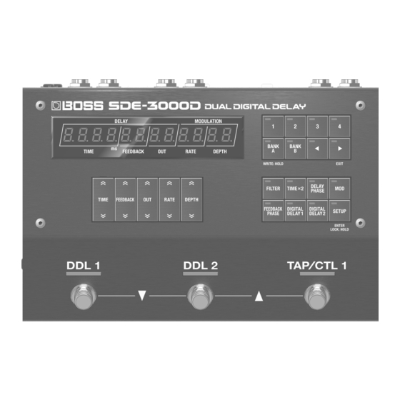
- Page 1 Reference Manual © 2023 Roland Corporation...
-
Page 2: Getting Ready
Getting Ready Attaching the Rubber Feet You can attach the rubber feet (included) if necessary. Attach them in the locations shown in the illustration. * Using the unit without rubber feet may damage the floor. * When turning the unit over, be careful so as to protect the buttons and knobs from damage. Also, handle the unit carefully; do not drop it. Connecting the Equipment Turning the Power On * To prevent malfunction and equipment failure, always turn... -
Page 3: Panel Descriptions
Panel Descriptions Top Panel Area Explanation Area Explanation Press the top part of each button to increase the value, and [FILTER] button press the bottom part of each button to decrease the value. A delay filter. This gives you a natural-sounding effect Long-press a button to make its value change rapidly. - Page 4 Getting Ready Switching Between Play Screen Displays The screen that appears after you turn on the power is called the “play screen”. Press the [ã] [â] buttons to switch between displays. Input level display Õ parameter display Õ BPM display Õ bank/memory display Parameter display Bank/memory display Bank...
-
Page 5: Rear Panel
Panel Descriptions Rear Panel Area Explanation Area Explanation INPUT L/MONO jack CTL4, 5/EXP2/GA-FC jack Connect your guitar or keyboard here. You can connect an expression pedal or footswitches and foot (*1) (*2) For a mono connection, use only the L/MONO jack. controllers to these jacks for controlling a variety of parameters. - Page 6 Panel Descriptions Configuring the Footswitch Mode The footswitch mode features a “manual mode” in which you can select one memory at a time in order, and “memory mode” in which you can select two memories at a time in order. Further, memory mode features an “immediate” mode that lets you select odd-numbered memories, and a “wait”...
- Page 7 Panel Descriptions Memory mode In this mode, the 100 memories are selected in sequential order, two at a time. Further, this mode features an “immediate” mode that lets you select odd-numbered memories, and a “wait” mode that lets you show two memories and then select a memory.
-
Page 8: Level Meter
Configuring the Input and Output Settings Use the DEPTH buttons to adjust the input level. Configuring the Input/Output to Match the Connected Device Adjusting the Output Level (Output Gain) To adjust the output level, change this value within a range of -12 to Press the [SETUP] button. - Page 9 Connecting an Amp and Configuring the Input/Output Settings The SDE-3000D has two built-in digital delays (Roland SDE-3000) that have been expanded to work in stereo. You can switch the configuration of these two delays between serial to parallel. The connection method is called a “structure”. For details on how to configure the input/output settings, refer to the information below.
- Page 10 Connecting an Amp and Configuring the Input/Output Settings Using a Single Amp (1-in, 1-out) Use the OUTPUT L/MONO jack when connecting to only one amp. The dry (direct) and wet (delay) sounds are mixed when output. IN OUT settings L/MONO INPUT [SETUP] Ó...
- Page 11 Connecting an Amp and Configuring the Input/Output Settings Using Two Amps (1-in, 2-out) Use the OUTPUT L/MONO and OUTPUT R jacks when connecting to two amps. This lets you mix the dry (direct) and wet (delay) sounds for output, or output the dry and wet sounds separately. When mixing the dry and wet sounds for output IN OUT settings L/MONO...
- Page 12 Connecting an Amp and Configuring the Input/Output Settings When outputting the dry and wet sounds separately IN OUT settings L/MONO INPUT [SETUP] Ó “ ” in;ovt Parameter Value Explanation [TIME] buttons [DEPTH] buttons The direct sound is output from diƐEFö diƐEFö...
- Page 13 Connecting an Amp and Configuring the Input/Output Settings Stereo Input/Output (2-in, 2-out) For stereo input, the dry (direct) and wet (delay) sounds are mixed when output. IN OUT settings Effect, keyboard, [SETUP] Ó “ ” in;ovt audio device Parameter Value INPUT L Explanation [TIME] buttons...
- Page 14 Using the Foot Volume Configuring the Foot Volume This is a volume control effect. Operate this with an expression pedal that’s connected to the CTL 2, 3/EXP1 jack or the CTL 4, 5/EXP2/GA-FC jack. Press the [SETUP] button. Use the [TIME] buttons to select “ ”.
-
Page 15: Selecting A Memory
Playing Selecting a Memory Press the [BANK A] button or the [BANK B] button to select a bank. Button (indicator color) Bank (memory) BANK A (1–4) [BANK A] button BANK B (1–4) [BANK B] button When you select a bank, the indicators for the memory buttons and the memory number in the display blink. - Page 16 Editing Configuring the Delay Sound Other Delay Parameters (DDL 1, DDL 2) (From the Top Panel) Press the [SETUP] button. Use the buttons to edit the parameters shown in the display. The parameter to set is shown in the display. Switch to the play screen parameter display (p.
- Page 17 Editing Setting the Left and Right Channels to the Same Parameter Value/Explanation Cuts the frequency region below the specified frequency Delay Time (Time Link: ON) (low-cut filter). d±Fb. L C. F (DDL 1 Feedback EQ Lo Freq) FLAt FLAt When you set the offset to “0” while Time Link is ON, the left and The low-cut filter has no effect.
- Page 18 Editing Use the [TIME] buttons to select “ ” or d±oFFSt d±oFFSt Switching Between Left and Right Time Display for “ ”, and then use the [DEPTH] buttons to d²oFFSt d²oFFSt DDL 1/DDL 2 change the value. Press the [DIGITAL DELAY 1] or [DIGITAL DELAY 2] ¸...
-
Page 19: Setting The Tempo
Editing Setting the Tempo Setting the Other Parameters (BPM) (MASTER) Here’s how to set the tempo when the delay time was set using a note length. Press the [SETUP] button. Use the [TIME] buttons to select “ ”. NASTER NASTER Press the [SETUP] button. -
Page 20: Useful Functions
Editing Useful Functions Operation Display The set value decreases [ã] button + [TIME (down)] button significantly. Switching Between Note Length and Time Display for the Delay Time Increase the setting value significantly When the play screen is showing the parameter, hold ¸... -
Page 21: Saving To Memory
Saving, Exchanging and Other Memory Operations Saving to Memory Swapping Memories (WRITE) (EXCHANGE) Here’s how to save the currently selected memory. Here’s how to swap (exchange) the memory number of the saved memory with a different one. Long-press the [BANK A] (WRITE) button. Long-press the [BANK A] (WRITE) button. - Page 22 Saving, Exchanging and Other Memory Operations Initializing a Memory (INITIALIZE) Here’s how to initialize the selected memory. Long-press the [BANK A] (WRITE) button. The write menu appears. ¸ ¸ ¸ ¸ ¸ ¸ ¸ ¸ ¸ ¸ ¸ ¸ ľ r i t E Use the [TIME] buttons to select “...
- Page 23 Preventing Accidental Operation (Panel Lock) You can enable (Lock OFF) or disable (Lock ON) the button operations. MEMO The panel lock setting is disabled when the power is turned off. Long-press the [SETUP] button to return to the play screen. The setting toggles between on and off each time you press the button.
-
Page 24: Connecting Footswitches
The polarity switch is set as shown in the illustration. Supported expression pedals Sold separately: BOSS EV-30, FV-500L, FV-500H, Roland EV-5 Footswitch CTL 2, 3/EXP 1 jack CTL4, 5/EXP2/GA-FC jack CTL 3... - Page 25 Configuring the External Controllers Configuring the CTL Function Parameter Value (CTL) Explanation [TIME] buttons [DEPTH] buttons C²nvN When you set (MEMORY NEŷnvN Press the [SETUP] button. (CTL 2 Number) NUMBER) for (CTL – C2. F nC Ʒ01 Ʒ01 – 2 Function)– (CTL 5 C5.
- Page 26 Configuring the External Controllers Assign parameters Assign Settings (ASSIGN) You can assign the functions you prefer to the [CTL 1] switch and to the Parameter Value Explanation [TIME] buttons [DEPTH] buttons footswitches you’ve connected. A±Sľ Up to eight assign settings can be saved for each memory. (Assign 1 Switch) Turns Assign 1–8 on/off.
- Page 27 Configuring the External Controllers Parameter Value Parameter Value Explanation Explanation [TIME] buttons [DEPTH] buttons [TIME] buttons [DEPTH] buttons This selects the function assigned to the controller. A±ACL Set the minimum/maximum values for each selected (Assign 1 ACT Low) function as a Min/Max value. Toggle between the “ ”...
- Page 28 Configuring the External Controllers Turning GAFC SW on GA-FC switch CH± CH± CH² CH² CH³ CH³ CH´ CH´ PnŸ PnŸ Etƭ Etƭ Press the [SETUP] button. (Ch1) (Ch2) (Ch3) (Ch4) (Panel) (Effects) GA-FC The parameter to set is shown in the display. Use the [TIME] buttons to select “...
- Page 29 Configuring the External Controllers GA-FC pedal jack Parameter Value Explanation [TIME] buttons [DEPTH] buttons GA-FC CH±d±HLd (CH1 DDL 1 Hold) When – CH±Fn EtµFn d±²HLd d±HoLd d²HoLd CH´d±HLd GA-FC EX (CH4 DDL 1 Hold) PnŸd±HLd (Panel DDL 1 Hold) Etƭd±HLd (Effects DDL 1 Hold) –...
- Page 30 Configuring the External Controllers Parameter Value Parameter Value Explanation Explanation [TIME] buttons [DEPTH] buttons [TIME] buttons [DEPTH] buttons When , or E±SƾF E²SƾF d±²HLd d±HoLd E±Sƾd1HL The GA-FC is not used. , you can set the Hold Level. (off ) d²HoLd (E1 Switch DDL 1 Hold Level) bPŷtAP...
-
Page 31: Connecting External Devices
Connecting with an External MIDI Device Connecting External Devices MIDI Settings (MIDI) Connect an external device to this unit via MIDI when you want to exchange MIDI messages or synchronize to a clock signal. Press the [SETUP] button. The parameter to set is shown in the display. MIDI (OUT/IN) jacks Use the [TIME] buttons to select “... - Page 32 Connecting with an External MIDI Device Parameter Value Parameter Value Explanation Explanation [TIME] buttons [DEPTH] buttons [TIME] buttons [DEPTH] buttons Specifies the input to which the tempo clock is d±NƞdPt synchronized. (DDL 1 Modulation Depth) Guaranteed operating range: 40–250 BPM d²NƞdPt Synchronizes with the internal (DDL 2 Modulation Depth)
- Page 33 Configuring the Program Change Map for the Memories You can use the program change map to customize which memories on the SDE-3000D correspond to which program change messages sent from an external MIDI device. Press the [SETUP] button. The parameter to set is shown in the display. Use the [TIME] buttons to select “...
-
Page 34: Connecting To A Computer
You must install the USB driver before connecting this unit to a USB MIDI computer. interface Download the USB driver from the BOSS website. Computer Install this special driver before making a USB connection. For details, refer to Readme.htm in the downloaded file. -
Page 35: System Settings
System Settings Configuring the Range of Memories Selectable Inheriting EXP Pedal Setting when Switching with the Foot Pedal Memory (Memory Extent) (EXP Hold) Press the [SETUP] button. Press the [SETUP] button. The parameter to set is shown in the display. The parameter to set is shown in the display. - Page 36 Restoring the Unit to the Factory Settings Here’s how to restore the SDE-3000D to its factory settings. Press the [SETUP] button. The parameter to set is shown in the display. ¸ ¸ ¸ ¸ ¸ ¸ ¸ ¸ ¸ ¸ ¸ ¸ i n ;...
-
Page 37: Main Specifications
* AF method (Adaptive Focus method) This is a proprietary OUTPUT (L/MONO, R) jacks: 1/4-inch phone type AD Conversion method from Roland & BOSS that vastly improves the signal- CTL2,3/EXP1 jack: 1/4-inch TRS phone type to-noise (SN) ratio of the AD and DA converters. -
Page 38: Preset List
Preset List A.01 The standard delay setting. This is a short delay with DDL 1 set to 500 msec and DDL 2 set to 250 msec. The delay gives a feeling of depth by combining two delays connected in series. STRUCTURE: SERI DRY+WET L... - Page 39 Preset List A.03 A delay with DDL 1 set to 800 msec (long) and DDL 2 set to 400 msec (medium). Turn DDL 2 on for a dreamlike long delay. STRUCTURE: SERI DRY+WET L DDL 1 (L/R) DRY+WET R Guitar DDL 1 parameter DDL 2 parameter DDL 1 SW:...
- Page 40 Preset List B.01 A delay sound with two delays connected in parallel (DDL 1: modulation delay, 500 msec; DDL 2: short delay, 250 msec). STRUCTURE: PARA1 DRY+WET L DDL 1 (L/R) DDL 2 (L/R) DRY+WET R Guitar DDL 1 parameter DDL 2 parameter DDL 1 SW: DDL 2 SW:...
- Page 41 Preset List B.03 A delay sound that combines a filter and modulation. STRUCTURE: PARA1 DRY+WET L DDL 1 (L/R) DDL 2 (L/R) DRY+WET R Guitar DDL 1 parameter DDL 2 parameter DDL 1 SW: DDL 2 SW: DDL 1 TYPE: STEREO DDL 2 TYPE: STEREO...