Table of Contents
Advertisement
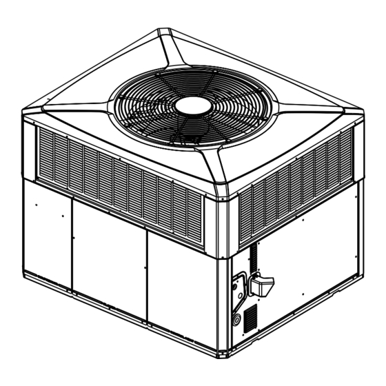
Installation and Operations Manual
Single Packaged Dual Fuel 15 SEER2 Convertible,
2 - 5 Ton, 60 - 115 KBTU, R-410A
4DCZ5024F1060A
4DCZ5036E1070A
4DCZ5048E1090A
4DCZ5060E1115A
Only qualified personnel should install and service the equipment. The installation, starting up, and servicing of heating, ventilating, and air-conditioning
equipment can be hazardous and requires specific knowledge and training. Improperly installed, adjusted or altered equipment by an unqualified person
could result in death or serious injury. When working on the equipment, observe all precautions in the literature and on the tags, stickers, and labels that
are attached to the equipment.
February 2023
S S A A F F E E T T Y Y W W A A R R N N I I N N G G
1 1 8 8 - - B B G G 0 0 7 7 D D 1 1 - - 1 1 B B - - E E N N
N N o o t t e e : : "Graphics in this document are for representation
only. Actual model may differ in appearance."
N N o o t t e e : : "Unit specific Service Facts available online."
Advertisement
Table of Contents

Related Manuals for Trane 4DCZ5024F1060A


Summary of Contents for Trane 4DCZ5024F1060A
- Page 1 Installation and Operations Manual Single Packaged Dual Fuel 15 SEER2 Convertible, 2 - 5 Ton, 60 - 115 KBTU, R-410A 4DCZ5024F1060A 4DCZ5036E1070A 4DCZ5048E1090A 4DCZ5060E1115A N N o o t t e e : : “Graphics in this document are for representation only.
- Page 2 SAFETY SECTION I I m m p p o o r r t t a a n n t t — This document contains a wiring C C A A U U T T I I O O N N diagram, a parts list, and service information.
-
Page 3: Table Of Contents
Table of Contents Introduction, Unit Inspection and Condensate Drain Piping ....18 Specification ....... 4 Gas Piping Installation . -
Page 4: Introduction, Unit Inspection And Specification
Introduction, Unit Inspection and Specification Introduction supply must be adequate for both the unit and all accessories. Read this manual carefully before attempting to install, 3. Check to be sure the refrigerant charge has been operate, or perform maintenance on this unit. retained during shipment. -
Page 5: Product Specifications
I I n n t t r r o o d d u u c c t t i i o o n n , , U U n n i i t t I I n n s s p p e e c c t t i i o o n n a a n n d d S S p p e e c c i i f f i i c c a a t t i i o o n n Product Specifications 4DCZ5024*1 4DCZ5036*1... - Page 6 I I n n t t r r o o d d u u c c t t i i o o n n , , U U n n i i t t I I n n s s p p e e c c t t i i o o n n a a n n d d S S p p e e c c i i f f i i c c a a t t i i o o n n 4DCZ5024*1 4DCZ5036*1 4DCZ5048*1...
-
Page 7: Charging In Cooling Above 55°F Od
I I n n t t r r o o d d u u c c t t i i o o n n , , U U n n i i t t I I n n s s p p e e c c t t i i o o n n a a n n d d S S p p e e c c i i f f i i c c a a t t i i o o n n Charging in Cooling above pressure under the subcool value column, Add refrigerant to raise the pressure to match the table,... -
Page 8: Determine Unit Clearances
Determine Unit Clearances Figure 1. Space on Sides Requirements 2 - 3 TON Units 4 - 5 TON Units RECOMMENDED SERVICE CLEARANCE mm [Inches] W/ ECONOMIZER W/ ECONOMIZER BACK SIDE 305 [12] 762 [30] 305 [12] 762 [30] LEFT SIDE 762 [30] 914 [36] 914 [36]... - Page 9 D D e e t t e e r r m m i i n n e e U U n n i i t t C C l l e e a a r r a a n n c c e e s s Figure 2.
-
Page 10: Information
Review Location and Recommendation Information N N o o t t e e s s : : inadequate should be reviewed with a local engineer. • The unit is shipped for horizontal installation. 3. See the unit’s nameplate for the absolute minimum •... - Page 11 R R e e v v i i e e w w L L o o c c a a t t i i o o n n a a n n d d R R e e c c o o m m m m e e n n d d a a t t i i o o n n I I n n f f o o r r m m a a t t i i o o n n 11.
-
Page 12: Unit Installation
Unit Installation N N o o t t e e : : The factory ships this unit for horizontal explained in the Ductwork Installation section. installation. 5. Flexible duct connectors must be of a flame retardant material. Insulate any ductwork outside of Install Flue Hood the structure with at least two (2) inches of insulation and weatherproof. -
Page 13: Lifting And Rigging
U U n n i i t t I I n n s s t t a a l l l l a a t t i i o o n n Table 1. Typical Ground Level Application Note: Use the extreme mounting kit, BAYEXMK003AA, to secure the unit to the slab. SIDING SUPPLY RETURN... -
Page 14: Rooftop Installation - Frame
U U n n i i t t I I n n s s t t a a l l l l a a t t i i o o n n Approximate unit weights are also provided in the P P l l a a c c i i n n g g t t h h e e U U n n i i t t o o n n t t h h e e M M o o u u n n t t i i n n g g C C u u r r b b unit drawings. -
Page 15: Rooftop Installation - No Curb
U U n n i i t t I I n n s s t t a a l l l l a a t t i i o o n n 7. Secure the unit to the frame. 2. Prepare the hole in the roof in advance of installing the unit. - Page 16 U U n n i i t t I I n n s s t t a a l l l l a a t t i i o o n n Table 5. Curb Dimensions This drawing was prepared by the manufacturer in order to provide detail regarding job layout only. This drawing is not intended to be used as a basis to construct, build or modify the item depicted in the drawing.
-
Page 17: Ductwork Installation
U U n n i i t t I I n n s s t t a a l l l l a a t t i i o o n n Table 7. Typical Rooftop Down Airflow Application with Frame Supply Return Air Roof Flashing... -
Page 18: Unit
U U n n i i t t I I n n s s t t a a l l l l a a t t i i o o n n Gas Piping Installation Attaching Horizontal Ductwork to Unit All conditioned air ductwork should be insulated to W W A A R R N N I I N N G G minimize heating and cooling duct losses. - Page 19 U U n n i i t t I I n n s s t t a a l l l l a a t t i i o o n n Table 9. Natural Gas Only Table 10. Gas Pipe TABLE OF CUBIC FEET PER HOUR OF GAS FOR DEALER INSTALLED VARIOUS PIPE SIZES AND LENGTHS...
- Page 20 U U n n i i t t I I n n s s t t a a l l l l a a t t i i o o n n • 1 Cu. Ft. Dial Gas Flow CFH = Chart Flow to the nameplate rating.
-
Page 21: Air Filter Installation
U U n n i i t t I I n n s s t t a a l l l l a a t t i i o o n n High Altitude Derate Chart Nat. Unit Input Altitude (In Feet) 115k 2001 3000... - Page 22 U U n n i i t t I I n n s s t t a a l l l l a a t t i i o o n n D D i i s s c c o o n n n n e e c c t t S S w w i i t t c c h h Table 14.
- Page 23 U U n n i i t t I I n n s s t t a a l l l l a a t t i i o o n n Table 16. Thermostat Wire Size and Max. Length T T W W O O M M O O D D E E S S O O F F O O P P E E R R A A T T I I O O N N : : The unit can be installed and configured to operate in Maximum Length...
- Page 24 U U n n i i t t I I n n s s t t a a l l l l a a t t i i o o n n Figure 7. Field Wiring Diagram Y2 (YL/RD) 2ND STAGE COMPRESSOR 1ST STAGE COMPRESSOR (CONSTANT CIRCULATION) 18-BG07D1-1B-EN...
-
Page 25: Unit Startup
Unit Startup Pre-Start Quick Checklist O O p p e e r r a a t t i i n n g g P P r r e e s s s s u u r r e e C C h h e e c c k k s s After the unit has operated in the cooling mode for a ☐... -
Page 26: Gas Furnace Heating Cycle
U U n n i i t t S S t t a a r r t t u u p p Starting the Unit in the Gas Heating H H e e a a t t P P u u m m p p H H e e a a t t i i n n g g S S h h u u t t D D o o w w n n Mode Place the system mode to OFF or adjust the heating setpoint below the room temperature. -
Page 27: Heating Shut-Down
U U n n i i t t S S t t a a r r t t u u p p Heating Shut-Down (W1) from the thermostat signals the control module (IGN) to run its self-check routine. After the control Set the comfort control to OFF or adjust the heating set module has verified that the pressure switch (PS) point to belowroom temperature. - Page 28 U U n n i i t t S S t t a a r r t t u u p p heating continuously or cycle between high fire gas N N o o t t e e : : Unlike the *CONT402, these two controls will not heating and low fire gas heating.
-
Page 29: Cooling Cycle
U U n n i i t t S S t t a a r r t t u u p p heating mode. Supplementary gas heat is brought on electronically commutated motor control (ECMC). (G) to control indoor temperature during the defrost cycle. provides power to the (ECMC) for low speed (ECM) indoor fan motor operation. -
Page 30: Maintenance
U U n n i i t t S S t t a a r r t t u u p p Maintenance • the unit (for obvious unit deterioration) H H e e a a t t i i n n g g S S e e a a s s o o n n Owner Maintenance Complete the following unit inspections and service W W A A R R N N I I N N G G... - Page 31 U U n n i i t t S S t t a a r r t t u u p p 13. Check all wires for correct installation by referring Figure 8. ECM Fan Control to the unit’s electrical wiring diagram in the SERVICE FACTS.
-
Page 32: Pressure Curves
U U n n i i t t S S t t a a r r t t u u p p Pressure Curves Figure 9. Pressure Curves for 4DCZ5024F Cooling with Thermal Expansion Valve Heating with Thermal Expansion Valve INDOOR ENTERING DRY BULB CURVES TOP TO BOTTOM INDOOR ENTERING DRY BULB CURVES TOP TO BOTTOM 71, 67, 63 AND 59 DEG F. - Page 33 U U n n i i t t S S t t a a r r t t u u p p Figure 10. Pressure Curves for 4DCZ5036E Cooling with Thermal Expansion Valve Heating with Thermal Expansion Valve INDOOR ENTERING WET BULB CURVES TOP TO BOTTOM INDOOR ENTERING DRY BULB CURVES TOP TO BOTTOM 71, 67, 63 AND 59 DEG F.
- Page 34 U U n n i i t t S S t t a a r r t t u u p p Figure 11. Pressure Curves for 4DCZ5048E Cooling with Thermal Expansion Valve Heating with Thermal Expansion Valve INDOOR ENTERING WET BULB CURVES TOP TO BOTTOM INDOOR ENTERING DRY BULB CURVES TOP TO BOTTOM 71, 67, 63 AND 59 DEG F.
- Page 35 U U n n i i t t S S t t a a r r t t u u p p Figure 12. Pressure Curves for 4DCZ5060E Cooling with Thermal Expansion Valve Heating with Thermal Expansion Valve INDOOR ENTERING WET BULB CURVES TOP TO BOTTOM INDOOR ENTERING DRY BULB CURVES TOP TO BOTTOM 71, 67, 63 AND 59 DEG F.
-
Page 36: Indoor Fan Performance
U U n n i i t t S S t t a a r r t t u u p p Indoor Fan Performance Table 18. Indoor Fan Performance 4DCZ5024*1 Horizontal Airflow [Cooling Down Airflow] (060) Motor Speed 350 CFM/ [601] [588] [571]... - Page 37 U U n n i i t t S S t t a a r r t t u u p p Table 19. Auxiliary Heating Airflow, Horizontal or Downflow from 0.2 to 0.6" wg Nominal Airflow 4DCZ5024 4DCZ5036 4DCZ5048 4DCZ5060 Switch Settings Selection...
-
Page 38: Refrigerant Circuit
U U n n i i t t S S t t a a r r t t u u p p Refrigerant Circuit Heating Refrigeration Cycle Cooling Refrigeration Cycle 18-BG07D1-1B-EN... -
Page 39: Troubleshooting Chart
U U n n i i t t S S t t a a r r t t u u p p Troubleshooting Chart P P - - P P R R I I M M A A R R Y Y C C A A U U S S E E S S / / S S - - S S E E C C O O N N D D A A R R Y Y C C A A U U S S E E S S SYSTEM FAULTS REFRIGERANT CIRCUIT Liquid Pressure too High... -
Page 40: Important Product Information
Service Phone ___________________________________________________________________ About Trane and American Standard Heating and Air Conditioning Trane and American Standard create comfortable, energy efficient indoor environments for residential applications. For more information, please visit www.trane.com or www.americanstandardair.com. The AHRI Certified mark indicates company participation in the AHRI Certification program. For verification of individual certified products, go to ahridirectory.org.