
Related Manuals for Omega CN4321


Summary of Contents for Omega CN4321
- Page 1 sales@artisantg.com artisantg.com (217) 352-9330 | Visit our website - Click HERE...
-
Page 2: Table Of Contents
Unpacking ..........6 CN4321 Model Configuration . -
Page 3: Introduction
4-20 mA output. Options available include alarms (configurable as high/low, deviation, or zone alarm). The CN4321 is a 1/32 DIN controller that has a single digital display. It is available with either single or dual outputs; dual output models can be used for heat/cool, heat/heat or cool/cool control. -
Page 4: Features
• High/low alarm • ABS plastic housing outputs (optional) • Termination– terminal block • Menu-driven format (CN4321) or socket with screw- • Setting – touch keys on front down terminals (CN4431) panel • 85 to 264V AC free voltage • Programmable 8-segment... -
Page 5: Safety Precautions
SAFETY PRECAUTIONS Before using this product, the user is requested to read the following precautions carefully to ensure safety. The safety requirements are classified as either “warning” or “caution” according to the following explanations: Warning Wiring 1. If there is danger of serious accident resulting from a failure or defect in this unit, provide the unit with an appropriate external pro- tective circuit to prevent an accident. - Page 6 Caution Installation 1. Avoid installing the unit in places where: • the ambient temperature may reach beyond the range of -10 to 50°C (14 to 122°F) while in operation • the ambient humidity may reach higher than 90% RH while in operation •...
-
Page 7: Unpacking
• 250Ω precision resistor (when required) (1) • Current transformer (when required) (1) ® If you have any questions about the shipment, please call the OMEGA Cus- tomer Service Department. When you receive the shipment, inspect the container and equipment for signs of damage. -
Page 8: Model Configuration
CN4321 MODEL CONFIGURATION MODEL DESCRIPTION Single Output Models _________________________________________________________________ CN4321(*)-R1 1/32 DIN controller, relay output CN4321(*)-D1 1/32 DIN controller, DC SSR driver output _________________________________________________________________ Dual Output Models _________________________________________________________________ CN4322(*)-R1-R2 1/32 DIN controller, dual relay output CN4322(*)-D1-R2 1/32 DIN controller, DC SSR driver and relay output... -
Page 9: Specifications
CN4321 SPECIFICATIONS INPUT RANGE TABLE: _________________________________________________________ Input Signal Input Range Input Range Remarks (°C) (°F) _________________________________________________________ Thermocouple* 0 ~ 800 32 ~ 1472 Cold Junction 0 ~ 1200 32 ~ 2192 compensating 0 ~ 1600 32 ~ 2912 function built-in... - Page 10 CONTROL FUNCTION (SINGLE OUTPUT) _________________________________________________________ Control action PID control with auto-tuning Fuzzy control with auto-tuning _________________________________________________________ Proportional band (P) 0-999.9% of full scale (FS), setting in 0.1% steps _________________________________________________________ Integral time (I) 0-3200 sec, setting in 1 sec steps _________________________________________________________ Differential time (D) 0-999.9 sec, setting in 0.1 sec steps _________________________________________________________...
- Page 11 _________________________________________________________ P,I,D= 0: On/Off action (without dead band) for heating and cooling I,D= 0: Proportional action _________________________________________________________ Proportional cycle 1-150 sec, for relay contact output and DC SSR driver output only _________________________________________________________ Hysteresis width On/Off action for heating and cooling: 0.5% FS On/Off action for cooling: 0.5% FS _________________________________________________________...
- Page 12 ADDITIONAL FUNCTIONS _________________________________________________________ 8-segment ramp-soak: 4 ramp/4 soak with 16 different modes Setpoint setting: 0-100% FS Ramp/soak period: 0-99 hrs 59 mins _________________________________________________________ Parameter mask: Parameters can be masked from being displayed _________________________________________________________ Self-diagnosis: Watchdog timer monitors program error _________________________________________________________ PROTECTION FROM POWER FAILURE _________________________________________________________ Memory protection:...
- Page 13 _________________________________________________________ Allowable signal Thermocouple: 100Ω or less source resistance: Voltage: 1KΩ or less _________________________________________________________ Allowable wiring RTD: 10Ω or less per wire resistance: _________________________________________________________ Reference junction ±1 °C (at 23°C) compensation accuracy: _________________________________________________________ Process variable offset: ±10% FS _________________________________________________________ Setpoint variable offset: ±50% FS _________________________________________________________ Input filter:...
-
Page 14: Outer Dimensions And Panel Cutout Size
OUTER DIMENSIONS & PANEL CUTOUT SIZE Outer Dimensions Panel Cutout Size When installing “n” number of units A: 57 (2.24) or more B: 34 (1.34) or more +0.5(0.02) +0.3(0.01) D: 22.2 (0.87) -
Page 15: Installation
INSTALLATION NEMA 4X Integrity The front side of this instrument conforms to NEMA 4X. To ensure the waterproofness between the instrument and the panel, use the gasket that is provided with the unit according to the installation procedure described below. 1. -
Page 16: Wiring Instructions
WIRING INSTRUCTIONS Terminal connection Warning Be sure to use the rated power supply voltage and polarity. * For current input, install the 250Ω precision resistor (accessory) before using the unit. Wiring material 1. For terminals 1, 2, 3, use 18 ~ 26 gauge wire. 2. -
Page 17: Front Panel Description
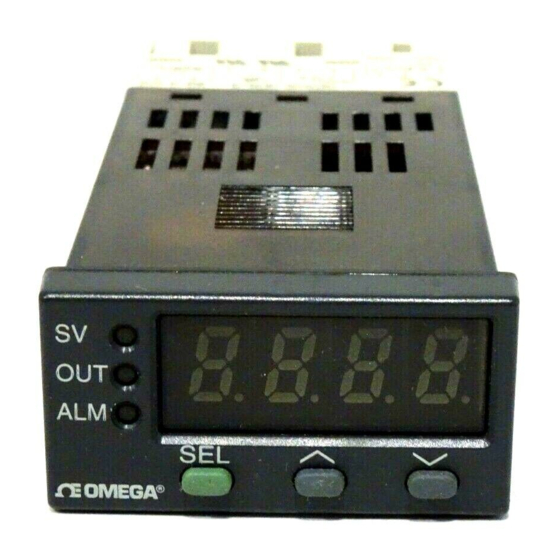
FRONT PANEL DESCRIPTION NAME FUNCTION 1 Set value (SV) Comes on when the set value (SV) indication lamp is displayed 2 Measured value (PV)/ Measured value (PV), Setpoint value (SV), Set value (SV)/ or parameter symbols and codes are parameter display displayed. -
Page 18: Front Panel Operation
FRONT PANEL OPERATION The programming menu consists of three blocks— SETUP MENU, SYSTEM MENU, and FACTORY PRESET MENU. At power up the controller will be in the operational mode– process variable (PV) will be displayed. This is the variable that is being controlled, and it is not programmable. When setting the parameters, turn off the power to the load (operating equipment) to ensure safety. - Page 19 5. Press SEL key to access the – AT 0, ..next parameter 6. Press SEL key for 3 secs. – Operational mode SYSTEM MENU Operation Display 1. Operational mode – Process value 2. Press and hold SEL key – 3 seconds later, “roFF” 7 seconds later, “P”...
-
Page 20: Model Configuration
CN4431 MODEL CONFIGURATION MODEL DESCRIPTION _________________________________________________________________ CN4431(*)-R1 1/16 DIN controller, relay output CN4431(*)-D1 1/16 DIN controller, DC SSR driver output CN4431(*)-F1 1/16 DIN controller, 4-20 mA DC output _________________________________________________________________ * Specify TR for Thermocouple/RTD input or CV for current/voltage input ALARM OPTION _________________________________________________________________ 2A, SPST relay... -
Page 21: Specifications
CN4431 SPECIFICATIONS INPUT RANGE TABLE: _________________________________________________________ Input Signal Input Range Input Range Remarks (°C) (°F) _________________________________________________________ Thermocouple* 0 ~ 800 32 ~ 1472 Cold Junction 0 ~ 1200 32 ~ 2192 compensating 0 ~ 1600 32 ~ 2912 function built-in 0 ~ 1800 32 ~ 3272 0 ~ 1600... - Page 22 CONTROL FUNCTION (SINGLE OUTPUT) _________________________________________________________ Control action PID control with auto-tuning Fuzzy control with auto-tuning _________________________________________________________ Proportional band (P) 0-999.9%, of full scale (FS), setting in 0.1% steps _________________________________________________________ Integral time (I) 0-3200 sec, setting in 1 sec steps _________________________________________________________ Differential time (D) 0-999.9 sec, setting in 0.1 sec steps _________________________________________________________...
- Page 23 ALARM _________________________________________________________ Alarm output 1-point relay contact (SPST), 220V AC/30V DC, 1A (resistive load) _________________________________________________________ SETTING AND INDICATION _________________________________________________________ Parameter setting method Digital setting with three keys _________________________________________________________ PV/SV display method Dual display for PV/SV 4 digits each, PV=red, SV=green _________________________________________________________ Status display Control output, alarm output...
- Page 24 _______________________________________________________ Withstand voltage Power source-Earth: 1500V AC, 1 min Power source-input terminal: 1500V AC, 1 min Earth-relay output: 1500V AC, 1 min Earth-Alarm output: 1500V AC, 1 min Between other terminals: 500V AC, 1 min _______________________________________________________ Input impedance Thermocouple: 1MΩ or more Voltage: 450KΩ...
- Page 25 OPERATING AND STORAGE CONDITIONS _______________________________________________________ Operating temperature -10 to 50°C (14 to 122°F) _______________________________________________________ Operating humidity Less than 90% RH (non-condensing) _______________________________________________________ Storage temperature -20 to 60°C (-4 to 140°F) _________________________________________________________ STRUCTURE _______________________________________________________ Mounting method Panel mounting or surface mounting _______________________________________________________ External terminal 8-pin or 11-pin socket...
-
Page 26: Outer Dimensions And Panel Cutout Size
OUTER DIMENSIONS & PANEL CUTOUT SIZE CN4431 Panel cutout size: when installing “n” numbers of units. A: 63 (2.48) or more +0.5(0.02) B: 45 (1.77) -
Page 27: Installation
INSTALLATION NEMA 4X Integrity The front side of this instrument conforms to NEMA 4X. To ensure the waterproofness between the instrument and the panel, use the gasket that is provided with the unit according to the installation procedure described below. How to install the unit Install the unit in the panel as shown below, and tighten the screws on the mounting bracket until the unit is secure. -
Page 28: Wiring Instructions
WIRING INSTRUCTIONS Warning Be sure to use the rated power supply voltage and polarity. * For current input, install the 250Ω precision resistor (accessory) before using the unit. - Page 29 Wiring Power to the Controllers • Be sure to use the rated power supply voltage and polarity to avoid failure or damage to the unit. • Keep the power off until all of the wiring is completed to prevent electric shock and abnormal operation. •...
- Page 30 • If using extension wires, make sure they are of the same thermo- couple material and grade; any dissimilar metal junctions will lead to erroneous readings. • Ungrounded thermocouples are recommended for optimal perfor- mance and to prevent ground loops. •...
- Page 31 • Use of MOV circuit is recommended to protect the relay against switching surges and to ensure the product’s long life. Connect it between the contacts of the relay as shown in the example below. Part No.: MOV-100 (power supply voltage: 100V) MOV-200 (power supply voltage: 200V) CN4431 CN4321 (8-pin) Z-Trap...
- Page 32 • The proportional time cycle parameter, “TC” is set to 0, and is not displayed on the programming menu. • Not available on CN4321. Wiring Alarms • Make sure the load does not exceed the rated capacity of the relay.
-
Page 33: System Wiring Diagrams
SYSTEM WIRING DIAGRAMS Example 1: Example 2:... -
Page 34: Front Panel Description
FRONT PANEL DESCRIPTION Name Function 1 Process Value (PV) display Displays the measured value. 2 Set value (SV) indication lamp Comes on while the set value is displayed. 3 Set value (SV) and Set value (SV), or parameter symbols and parameter display codes are displayed. -
Page 35: Front Panel Operation
FRONT PANEL OPERATION The CN4431 programming menu consists of three blocks— SETUP MENU, SYSTEM MENU, and FACTORY PRESET MENU. At power up the controller will be in the operational mode, and process variable (PV) and setpoint variable (SV) will be displayed. PV is the variable that is being controlled, and it is not programmable. - Page 36 5. Press SEL key to access the – ‘L’ LED blinks, ..next parameter 6. Press SEL key for 3 secs. – Operational mode SYSTEM MENU Operation Display 1. Operational mode – PV, SV 2. Press and hold SEL key –...
-
Page 37: Autotuning
AUTOTUNING Before initiating the autotune function, first decide if you would like to autotune at setpoint or 10% of full scale below setpoint. Set the set- point (SV), alarms (AL, AH) and the cycle time (TC). Bring your process near setpoint before starting the autotune procedure. Autotuning works best for heating processes in which the setpoint is 100°F (60°C) above ambient temperature. -
Page 38: Setup Menu
SETUP MENU See Quick Reference (p.74) for a listing of the menu. PARAMETER DESCRIPTION roFF - rhLd Ramp/Soak Command: The Ramp/Soak program auto- matically changes the setpoint value with time according to a preset pattern. Setting: roFF : Normal operation is performed rrUn : Ramp/Soak operation is performed rhLd : Ramp/Soak operation is suspended rEnd indicates that the operation is terminated. - Page 39 Set within the Input Range. Not indicated without the alarm option, or in CN4321. Autotuning: Autotuning is the automatic calculation and entering of the control parameters (P, I and D) into memo- ry. Autotuning will also automatically set anti-reset wind- up (Ar).There are two types of Autotuning that can be...
- Page 40 Parameter lock: This function enables or disables changing the settings of parameters. Code: 0 - All parameter settings are changeable 1 - All parameter settings are locked; cannot be changed 2 - Only the main setpoint can be changed; all other parameter settings are locked and cannot be changed.
-
Page 41: System Menu
SYSTEM MENU Proportional Band: The proportional band is that area around main setpoint where the control output is neither fully on nor fully off. Setting range: 0.0 to 999.9% of full scale For On/Off control, set to “0” Integral Time (reset): The Integral Time is the speed at which a corrective increase or decrease in output is made to compensate for offset which usually accompa- nies proportional only processes. - Page 42 Cycle Time (Output #1): The Cycle Time for output #1 is that time where the output is on for a percentage of that time and off for a percentage of that time, creating a proportioning effect. The Cycle Time is only used when P, PI, PD, or PID control action is used, and when the output is time proportional as with the relay or SSR dri- ver outputs.
- Page 43 Hysteresis: Hysteresis is that area around the main set- point where the output does not change condition. That area or deadband is intended to eliminate relay chatter at setpoint for On/Off control applications. The wider the Hysteresis, the longer it takes for the controller to change output condition.
- Page 44 Cycle Time (Output #2) The Cycle Time for output #2 is similar in function to Cycle Time for output #1. Output #2 is the cooling side of heat/cool controller CN4321. Enter a value that is based on the limitations of your con- troller’s output type.
- Page 45 Deadband/Overlap...
- Page 46 powerful cooling loads. Enter a value based on the power of your cooling load. Setting Range: 0.0 to 100.0 Not indicated without control output #2 option. Set to “0” for On/Off control. Deadband/Overlap: The Deadband/Overlap is that per- centage of the heating side of the proportional band where the heating (output #1) and the cooling (output #2) outputs are separated by a deadband or where they overlap on a heat/cool controller.
- Page 47 heat/cool control. Setting range: -50.0 to 50.0% of the heating proportional band. Not indicated without control output #2 option Balance: Balance is used to pre-position the proportional band with respect to setpoint. With Balance (MV Offset) set at 50% the proportional band will be centered around setpoint.
- Page 48 Table of Input Type Codes...
- Page 49 use the resistor if a voltage signal is applied directly. After the appropriate physical changes have been made, the controller will still need the correct code for the input type to be used. Enter the appropriate code from the Table of Input Type Codes. P-SL Lower Limit of Input Range: The Lower Limit of Input Range is that value which establishes the desired low...
- Page 51 limit for the type of input used. The value must be less than or equal to the input type’s highest limit. Setpoint settings are restricted to values less than the high limit. Parameters which are calculated as a percentage of full scale are affected by this setting.
- Page 52 The high and low alarm setpoints are set with primary menu parameters AH and AL (AL is not applicable in the case of CN4321). The absolute alarm configurations are independent of main setpoint. The alarm output relays are energized when the process variable exceeds the alarm setpoint, an absolute value.
- Page 53 Table of Alarm Action Type Codes—CN4321...
- Page 54 Table of Alarm Action Type Codes—CN4431...
- Page 55 Enter the code for P-AH and P-AL from the Table of Alarm Action Type Codes. See pages 57 & 58. P-AL is not applicable in the case of CN4321. Note 1: A change of alarm action type can cause the alarm set value to change, but this is not a malfunction.
- Page 56 troller to control a process other than temperature using the current/voltage input model, the C/F Selection is not important because the scaling is done using the lower limit of the input range and upper limit of input range parameters, and the indication is in engineering units. Setting: °C or °F STAT Ramp/Soak Status: The Ramp/Soak program automati- cally changes the setpoint value with time in accordance...
- Page 57 Table of Ramp/Soak Modes MOD Power on start Output on END Output on OFF Repeat function Continue controlling Continue controlling Continue controlling Continue controlling Yes Continue controlling Stand-by mode Continue controlling Stand-by mode Stand-by mode Continue controlling Stand-by mode Continue controlling Yes Stand-by mode Stand-by mode Stand-by mode...
-
Page 58: Factory Preset Menu
oFF: Not in operation 1-rP – 4-rP: Executing 1st – 4th ramp 1-St – 4-St: Executing 1st – 4th soak End: End of program SV-1 Ramp Target Value: Sets the target value for each ramp segment. SV-4 Setting range: 0-100% of full scale TM1r Ramp Segment Time: Sets the duration of each ramp segment. - Page 59 Table of Output Type Codes...
- Page 60 application would require reverse acting control. In a direct-acting controller, the output increases as the process variable increases. A cooling application would require direct-acting control. Enter the code from the Table of Output Type Codes which establishes the con- troller as either a reverse or direct-acting controller. The Sensor Burn-out Protection is the intended direc- tion of the output in the event of a thermocouple or RTD sensor break, or a break in the analog input.
- Page 61 time, the controller averages out the peaks and valleys of a dynamic system which, in turn, stabilizes the control. The digital filter also aids in controlling processes where the electrical noise is affecting the input signal. The larg- er the value entered, the more filter added and the slow- er the controller reacts to process variable changes.
- Page 62 FUZY Fuzzy Logic Control: Employing Fuzzy Logic Control in addition to PID control eliminates system overshoot and effectively suppresses fluctuation of the process vari- able due to external disturbances. This function may be enabled even during auto-tuning. Note that fuzzy control is not effective in units with dual outputs, due to the complexity of the process.
-
Page 63: Error Messages
ERROR MESSAGES Error Indication Cause Control Output 1. Thermocouple burnt out. When the burn-out 2. RTD (A) leg burnt out. control output is set for 3. PV value exceeds P-SU lower limit (standard): by 5% FS. OFF, or 4mA or less. 1. -
Page 64: Appendix A: Autotuning
APPENDIX A Autotuning By autotuning, the controller selects what it calculates to be the optimal PID control parameters for a particular process and then stores them in EEPROM memory for future use. The PID parameters are stored so that when the controller is powered up after being shut down, the controller does not need to be autotuned again. - Page 65 very dynamic. Because of how the Autotune function is performed, a very dynamic system would create very large overshoots which could damage the process. 3. The system is very insulated and cannot cool down in a timely man- ner. With such heating systems the autotuning function would take a long time to complete, with questionable results.
- Page 66 controller then reads the reaction of these test signals on the process. Keep in mind that every process is different and therefore every reac- tion to the test signals is different. This is why PID parameters are not the same for all processes. The amplitude (L) or lag time which is the overshoot and undershoot of the system when autotuning, and the time constant (T) which is the time the process takes to go through one On/Off cycle are measured.
-
Page 67: Appendix B: Manual Tuning
(SV) and the process variable (PV). Outside of the proportional band the out- put is either 0% or 100% The proportional band on CN4321/CN4431 is equidistant from the main setpoint as illustrated below. - Page 68 An example of proportioning would be a vehicle approaching a stop sign at an intersection. If the driver were traveling at 50mph and only applied his brakes once at the intersection, his car would skid through the inter- section before coming to a full stop. This illustrates how On/Off control acts.
- Page 69 reactive the output becomes. A proportional band too small, however, can lead to over-responsiveness leading to process oscillation. A proportional band which is correct in width approaches main setpoint as fast as possible while minimizing overshoot. If a faster approach to setpoint is desired and process overshoot is not a problem, a smaller or narrower proportional band may be used.
- Page 70 Integral Time With the proportional band alone, the process tends to reach equilibri- um at some point away from the main setpoint. This offset is due to the difference between the output needed to maintain setpoint and the out- put of the proportional band at setpoint. Since the proportional band is equidistant from the main setpoint, the output is around 50%.
- Page 71 Integral Time is the speed at which the controller corrects for offset. A short integral time means the controller corrects for offset quickly. If the integral time is too short, the controller would react before the effects of previous output shifts–due to lead or lag time–could be sensed, causing oscillation.
- Page 72 The derivative action changes the rate of reset or integration propor- tional to the rate of change and lag time of the system. By calculating the rate of change of the process and multiplying it by the lag time which is the time it takes the controller to sense an output change, the controller can anticipate where the process should be and change the output accordingly.
- Page 73 Tuning Tuning, as with any PID loop, requires tuning each parameter separate- ly and in sequence. To achieve good PID control manually, you can use the trial and error method explained below. Tune the Proportional Band Set Integral Time = 0 (off) Set Derivative Time = 0 (off) Start with a large Proportional Band value which gives very sluggish control with noticeable offset and tighten by decreasing the value in...
- Page 74 Add Derivative Time Do not add Derivative Time if the system is too dynamic. Start with a small Derivative Time value which gives sluggish response to process upsets and double the value. Analyze the process variable. If the response to process upsets is still sluggish, double the value again. Continue with the same procedure until the process starts to oscillate at a quick constant rate.
- Page 75 4. Widen the Proportional Band until only slightly unstable. This is the Proportional Band’s Ultimate Sensitivity. The Proportional Band’s Ultimate Sensitivity width will be defined as “P” when calculating the actual Proportional Band. 5. Use the following coefficients in determining the correct PID settings for your particular application.
-
Page 76: Appendix C: Heat/Cool Option
The two outputs on the CN4321 are independent and sent to two differ- ent output devices. The first output could be either a relay or a DC SSR driver, while the second output has to be a relay output only. - Page 77 Notes: 1. The Heat/Cool Option is available on the CN4321 controller only. Output #2 can be a relay output only. 2. Integral and Derivative Times are the same for both the heating and...
- Page 78 Wiring and Setting 1. Make sure that the controller has a relay installed for Output #2. Verify that parameters TC2, COOL, and db are indicated in the Setup menu. 2. Wire your cooling load to the Output #2 terminals located on the back of the controller.
- Page 79 Heating Side Cooling SIde Heating Proportional Band Cooling Proportional Band [P/2] [P/2 COOL] I (same as for heating) D (same as for heating) somewhere between 0% and 50% of the Heating Proportional band. To establish an Overlap, “db” is set somewhere between -50% and 0% of the Heating Proportional Band.
-
Page 80: Quick Reference
CN4321/CN4431 QUICK REFERENCE Setup Menu Parameter Range Description Default settings settings roFF - rHLd roFF/rrUn/rHLd Ramp/soak command roFF dSP1-1 0 - 100%FS High Alarm Setpoint dSP1-2 0 - 100%FS Low Alarm Setpoint dSP1-4 dSP1-8 0 - 2 Auto-tuning dSP1-16 0 - 2... - Page 81 Parameter Range Description Default settings settings P-SU -1999 - 9999 Upper range of input 100%FS dSP3-8 P-dP 0 - 2 Decimal point position dSP3-16 P-AH 0 - 11 Alarm Type 1 code dSP3-32 P-AL 0 - 15 Alarm Type 2 code dSP3-64 PVOF -10 - 10%FS PV offset...
- Page 82 PCUT - dSP7-2 FUZY OFF/ON Fuzzy control dSP7-4 GAIN - dSP7-8 ADJ0 - Zero calibration dSP7-16 ADJS - Span calibration dSP7-32 -3.0 dSP7-64 dSP1-7 0-255 Parameter mask † Not applicable to CN4321 Not applicable to CN4431 Based on the model †...