Table of Contents
Advertisement
Quick Links
THIS MANUAL MUST BE LEFT WITH THE
BUILDING OWNER FOR FUTURE REFERENCE
WARNING
Improper installation, adjustment, alteration, service
or maintenance can cause property damage, personal
injury or loss of life. Installation and service must be
performed by a licensed professional HVAC installer or
equivalent, or service agency.
IMPORTANT
The Clean Air Act of 1990 bans the intentional venting of
refrigerant (CFCs, HCFCs and HFCs) as of July 1, 1992.
Approved methods of recovery, recycling or reclaiming
must be followed. Fines and/or incarceration may be
levied for noncompliance.
CAUTION
As with any mechanical equipment, contact with sharp
sheet metal edges can result in personal injury. Take
care while handling this equipment and wear gloves and
protective clothing.
WARNING
To prevent serious injury or death:
1. Lock-out/tag-out before performing maintenance.
2. If system power is required (e.g., smoke detector
maintenance), disable power to blower, remove fan
belt where applicable, and ensure all controllers
and thermostats are set to the "OFF" position before
performing maintenance.
3. Always keep hands, hair, clothing, jewelry, tools, etc.
away from moving parts.
INSTALLATION
INSTRUCTIONS
®
Elite
ELXC Series
6 - 20 Ton
AIR CONDITIONERS
6 - 20 TONS
508322-01
10/2022
Table of Contents
Model Number Identification ..........................................2
Unit Plumbing Parts Arrangement ..................................6
Unit Control Box Components Arrangement ................12
Rigging the Unit for Lifting ...........................................13
Installation Clearances ................................................14
Line Set .......................................................................14
Electrical Connections .................................................15
Refrigerant Charge ......................................................21
System Operation ........................................................21
Maintenance ................................................................22
Shipping and Packing List
Check the unit for shipping damage. If damaged or parts
are missing, immediately contact the last shipping carrier.
1 - Assembled outdoor unit
1 - Installation instructions
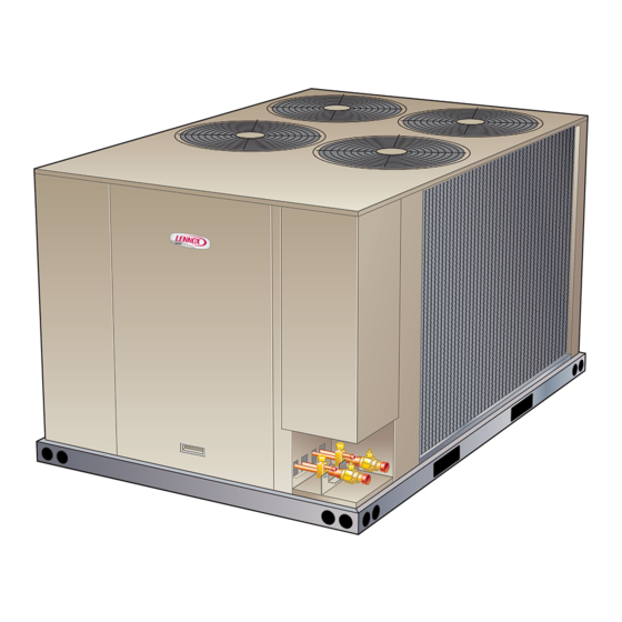
Outdoor Unit
Elite Series air conditioners, which will also be referred to
in this instruction as the outdoor unit, use HFC-410A re-
frigerant. This outdoor unit must be installed with a match-
ing indoor unit and line set as outlined in the Elite Series
Engineering Handbook.
This outdoor unit is designed for use in thermal expansion
valve (TXV) systems only.
Page 1
Advertisement
Table of Contents

Related Manuals for Lennox Elite ELXC Series


Summary of Contents for Lennox Elite ELXC Series
-
Page 1: Table Of Contents
INSTALLATION INSTRUCTIONS ® Elite ELXC Series 6 – 20 Ton AIR CONDITIONERS 6 - 20 TONS 508322-01 10/2022 THIS MANUAL MUST BE LEFT WITH THE BUILDING OWNER FOR FUTURE REFERENCE Table of Contents Model Number Identification ..........2 WARNING Unit Dimensions, Corner Weights and Centers of Gravity 3 Unit Plumbing Parts Arrangement ........6 Improper installation, adjustment, alteration, service Unit Control Box Components Arrangement ....12... -
Page 2: Model Number Identification
Model Number Identification EL 120 X C S D T 1 Y Brand/Family Voltage EL = Elite ® Product Line Y = 208/230V-3 phase-60Hz G = 460V-3 phase-60Hz J = 575V-3 phase-60Hz Nominal Cooling Capacity − Tons 072 = 6 Tons Minor Design Sequence 090 = 7.5 Tons 1 = 1st Revision... -
Page 3: Unit Dimensions, Corner Weights And Centers Of Gravity
Unit Dimensions, Corner Weights and Centers of Gravity E L 0 7 2 X C | E L 0 9 0XC CORNER WEIGHTS CENTER OF GRAVITY Model lbs. lbs. lbs. lbs. EL072XCSS 23-1/4 19-1/4 EL090XCSS 20-1/4 9-1/8 INLET AIR (232) LIQUID CENTER OF LINE... - Page 4 EL 120X C | E L150XC CORNER WEIGHTS CENTER OF GRAVITY Model lbs. lbs. lbs. lbs. EL120XCSS 20-1/2 33-1/2 EL120XCSD 28-1/2 EL150XCSD INLET AIR 9-1/8 OUTDOOR FAN (232) GUARDS (2) 6-1/2 (165) CENTER OF LIQUID GRAVITY 3-3/4 LINES (95) 1-1/8 SUCTION LINES (29)
- Page 5 EL1 8 0X C | EL2 4 0XC CORNER WEIGHTS CENTER OF GRAVITY Model lbs. lbs. lbs. lbs. EL180XCSD EL240XCSD 37-1/2 OUTDOOR FAN INLET 9-1/8 LIQUID GUARDS (4) (232) LINE (2) SUCTION 6-1/2 LINE (2) (165) 3-3/4 (95) CENTER OF 1-1/8 GRAVITY (29)
-
Page 6: Unit Plumbing Parts Arrangement
Unit Plumbing Parts Arrangement EL072XCSS EL090XCSS Page 6... - Page 7 EL120XCSS EL120XCSD – STAGE 2 Page 7...
- Page 8 EL120XCSD – STAGE 1 EL150XCSD – STAGE 2 Page 8...
- Page 9 EL150XCSD – STAGE 1 EL180XCSD – STAGE 2 Page 9...
- Page 10 EL180XCSD – STAGE 1 EL240XCSD – STAGE 2 Page 10...
- Page 11 EL240XCSD – STAGE 1 Page 11...
-
Page 12: Unit Control Box Components Arrangement
Unit Control Box Components Arrangement Page 12... -
Page 13: Rigging The Unit For Lifting
Rigging the Unit for Lifting Lifting point should be directly above the center of gravity. Caution - do not walk on unit Rig the unit for lifting by attaching four cables to the holes in the base rail of the unit. See figures 1 through 3. 1 - Remove protective packaging before rigging the unit for lifting. -
Page 14: Installation Clearances
1 (excluding equivalent length of fittings). Size refrigerant lines greater than 50 linear feet FIGURE 5. ELITE SERIES AIR CONDITIONERS (15m or greater) according to the Lennox Refrigerant Pip- (Two Fans) Installation Clearances ing Design and Fabrication Guidelines (Corp. 9351-L9) or latest version. -
Page 15: Electrical Connections
Electrical Connections TYPICAL HIGH VOLTAGE POWER SUPPLY CONNECTIONS In the United States, wiring must conform with current lo- cal codes and the current National Electric Code (NEC). In Canada, wiring must conform with current local codes and the current Canadian Electrical Code (CEC). SINGLE COMPRESSOR MODELS TRANSFORMER –... - Page 16 24 VAC FIGURE 7. Typical Field Wiring – Single Compressor 24 VAC FIGURE 8. Typical Field Wiring – Two Compressors Page 16...
- Page 17 TYPICAL UNIT CONTROL WIRE CONNECTIONS WIRE RUN LENGTH AWG# INSULATION TYPE LESS THAN 100’ (30M) TEMPERATURE RATING MORE THAN 100’ (30M) 35°C MINIMUM RUN CONTROL WIRES THROUGH RIGHT CUTOUT. RUN CONTROL WIRES THROUGH WIRE TIES. TIGHTEN WIRE TIE TO SECURE 24VDC CONTROL WIRING. NOTE - FOR PROPER VOLTAGES, SELECT THERMOSTAT WIRE (CONTROL WIRING) GAUGE PER TABLE ABOVE.
- Page 18 FIGURE 9. Typical Wiring Diagram – Elite Series Air Conditioners Page 18...
- Page 19 TB14 DL58 COOL 3 TB14 COOL 2 TB14 COOL 1 TB14 TB14 COMPONENT COMPONENT SWITCH, LIMIT HI PRESS COMPRESS 1 SWITCH, LIMIT HI PRESS COMPRESS 2 SWITCH, LOSS OF CHARGE COMPRESS 1 SWITCH, LOSS OF CHARGE COMPRESS 2 TRANSFORMER, CONTROL TERMINAL STRIP, UNIT DENOTES OPTIONAL COMPONENTS LINE VOLTAGE FIELD INSTALLED...
- Page 20 TB14 DL58 COOL 3 TB14 COOL 2 TB14 COOL 1 TB14 TB14 COMPONENT COMPONENT SOLENOID, TWO STAGE, COMP. 2 SWITCH, LIMIT HI PRESS COMPRESS 1 SWITCH, LIMIT HI PRESS COMPRESS 2 SWITCH, LOSS OF CHARGE COMPRESS 1 SWITCH, LOSS OF CHARGE COMPRESS 2 TRANSFORMER, CONTROL TERMINAL STRIP, UNIT DENOTES OPTIONAL COMPONENTS...
-
Page 21: Refrigerant Charge
For all other unit matches, please COOLING 2 C1+C2 HIGH contact Lennox Commercial Application department for Footnotes: Charging Procedure Information (form # 508349-01). 1. Refer to Component Label or Wiring Diagram for key numbers. 2. 24V input signals measured between one TB14 connection listed and Split System Matches TB14-C connection. -
Page 22: Maintenance
EL180XC, EL240XC Input Signals at Thermostat Demand Compressor Output Fans Terminal Strip² (Key Number1) (TB14) (B1) (B2) (B4) (B5) (B21) (B22) STANDBY COOLING 1 COOLING 2 C1+C2 COOLING 3 C1+C2+C3 HIGH HIGH Footnotes: 1. Refer to Component Label or Wiring Diagram for key numbers. 2. - Page 23 Start-Up and Performance Checklist Job Name Job no. Date Job Location City State Installer City State Unit Model No. Serial No. Service Technician Nameplate Voltage Rated Load Ampacity Compressor Amperage: Maximum Fuse or Circuit Breaker Electrical Connections Tight? Indoor Filter clean? Supply Voltage (Unit Off) Indoor Blower RPM S.P.