
Related Manuals for Haier L42H8


Summary of Contents for Haier L42H8
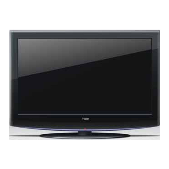
- Page 1 Order NO.WH070625S001V0 L42H8 (MST6E89) (2007)(Haier Electronic Company Limited) All rights reserved. Unauthorized copying and distribution is a violation of law.
-
Page 2: Table Of Contents
WARNING This service information is designed for experienced repair technicians only and is not designed for use by the general public. It does not contain warnings or cautions to advise non-technical individuals of potential dangers in attempting to service a product. Products powered by electricity should be serviced or repaired only by experienced professional technicians. -
Page 3: Specifications
1. Specification Model L42H8 Screen size Aspect ratio 16:9 Resolution 1366 x 768 Response Time ms) Angel of view H:178 /V:178 Color display 16.7M NO.of preset channels OSD language English/Simple Chinese Color system Audio system Audio output power(Built-in)(W) 7W X2... - Page 4 THIS SYMBOL INDICATES THAT HIGH VOLTAGE IS PRESENT INSIDE . IT IS DANGEROUS TO MAKE ANY KING OF CONTACT WITH ANY INSIDE PART OF THIS PRODUCT. THIS SYMBOL INDICATES THAT THERE ARE IMPORTANT OPERATING AND MAINTENANCE INSTRUCTIONS IN THE LITERATURE ACCOMPANYING THE APPLIANCE.
-
Page 5: Location Of Controls And Components
SAVE THESE INSTRUCTIONS Thank you for using our Haier product. This easy-to-use manual will guide you in getting the best use of your product. Remember to record the model and serial number. They are on label in back of the unit. -
Page 6: Side Av Board
3.2.1 Function Description: Process signal which incept from Tunner then translate into signal which panel can display. 3.3Side AV Board(Fasened on the Rear Cover) -
Page 7: Power Board
3.4Power Board 3.4.1 Function Description: Supply power for Main board and Panel. 3.4.2 Connector definition PIN NUMBER Designation PIN NUMBER Designation ON/OFF... -
Page 8: Lcd Panel
5VSB PIN NUMBER Designation 16.5V 16.5V LCD PANNEL 3.5.1 Function Description: Display the signal. 3.5.2 Connector defination MODULE CONNECTOR (CN1) PIN CONFIGURATION LCD Connector (CN1): FI-X30SSL-HF (Manufactured by JAE) or Equivalent Mating Connector: FI-30C2L (Manufactured by JAE) or Equivalent... - Page 9 Note: 1. The pin no 9 is an option pin for DISM or LG format. (LG Format=”GND” or “OPEN”/DISM Format=”VCC”) 2. The pin no 10 is an option pin for DCR Function (Enable=”VCC”/Disable=”GND”) 3. The pin no 30 is LCD Test option. “AGP”...
-
Page 10: Features And Techinical Description
4. FEATURES AND TECHINICAL DESCRIPTION TFT/CRT LC420WX7 Display area 42 inches Aspect ratio 16:9 Resolution 1366*768 Brightness 500cd/m2 Contrast(Darkroom) 1500:1 Response time(ms) Analog Color system digital Color system Picture Audio system Angel of view NO.of preset channels Picture mode Color display 16.7 M OSD languages English/Simple Chinese... - Page 11 Treble SOUND Digital Bass Super woofer Treble/bass boost AV stereo Surrounding sound BTSC Automatic Volume Control(AVC) Auto-volume leveling Equalizer Mute Multi-audio modes Multi-sound mode Side AV input Rear AV input AV output DVD terminal S-video jack YCbCr Y PB PR Jack D-SUB jack DVI socket...
-
Page 12: Installation Instructions
Electricity Voltage range V 150-240V parameter Power frequency Hz 50/60Hz Time of sleep timer(MINS) Net weight kg 24.9 Net weight(Including Base) kg 31.6 Gross weight kg 31.6 Gross weight(Including Base) kg 31.6 Net dimension(mm) 1023*328*730 Net dimension (Including Base) mm 1023*328*730 Packaged dimension mm 1115*375*830... -
Page 13: External Equipment Connections
What is the size and weight of your TV? All brackets have weight and size restrictions. It is necessary to make sure your TV will fit within the limitations of the mount. Are you going to fit the mount into a tight space or cabinetry? It may be impossible to use some brackets if the space does not allow the proper leverage. - Page 14 5.1.2 VCR Connections --To avoid picture noise (interference),leave an adequate distance between the VCR and TV.
- Page 15 5.1.3 HDMI Connections 5.1.4 DVD Connections...
- Page 16 5.1.5 PC Connections...
-
Page 17: Operation Instructions
6. OPERATION INSTRUCTIONS Basal information 6.1 Front panel controls 6.2 Back panel controls... -
Page 18: Setting Up Your Remote Control
6.3 Setting Up Your Remote Control... -
Page 20: Disassembly Instructions
7. DISASSEMBLY INSTRUCTIONS 7.1.whole machine... -
Page 21: Connection Sketch Interpretat
7.2 Connection Sketch Interpretat And Wiring Conection Diagram Name Parts number LVDS WIRE 0090400338B 12V/ 5V Wire 0090403469A 16.5v Wire 0090403399F Speaker Wire 0090403308B Side AV Wire 0090402508A Ground Wire 0090403319 Control and Remote wire 0090403138E Backlight wire 0090401790 Inner wire 0090403320C 8. -
Page 22: The Default Of Factory Mode Menu
8.2 The default of Factory Mode Menu 8.2.1 The Main Menu In factory mode menu press CH+/- to choose the up/down item press VOL+/- to the submenu press MENU return to the last item. FACTORY MENU SOURCE ADC ADJ PICTURE MODE SOUND MODE COLOR TEMP EEPROM ADJUST... -
Page 23: Block Diagram And Circuit Diagram
Source Sound Mode Standard Bass Treble 5 COLOR TEMP Source Color Temp Standard R GAIN G GAIN B GAIN R OFF G OFF B OFF 6 EEPROM ADJUST ADDR. DATA SAVE 7 NON LINEAR Contrast > Brightness > Sharpness > Color >... - Page 24 VIDEO INPUT&OUTPUT MODULE AUDIO OUT MODULE HDMI1 DDR SDRAM(128M,16BIT) HDMI2 ADDR DATA DVIRX0 SCART1 OUT AUOUTR/L3 YPbPr1 DVIRX1 GAIN R1,G1,B1,Hs,Vs DVB(option) (option) R2,G2,B2 AUOUTR/L2 SCART2 OUT GAIN YPbPr2 R0,G0,B0 AV OUT(FOR CHINA) SCART1OUT SCART1/AV1 HEADPHONE CVBS2 AUOUTR/L0 AUOUTR/L1 TFA9810T CVBS3 SPEAKER Y0,C0 SCART2...
- Page 25 Version history I/O port distribute MST6X89CL PIN name&Usage MST BANK Register Version 1.0 Initial Release ON_USB PIN186:GPIOB[6]==P2.6. BKA_E8[5:4]=10 01.Power: update Backlight adjust circuit SDA_EXT PIN154:AD[0]==P1.0. BKA_E9[7:6]=10 02.MST6x89CL:add HPLUGA/B pull up resistor SCL_EXT PIN155:AD[1]==P1.1. BKA_EA[1:0]=10 02.MST6x89CL:Enable EEPROM WP control function AMP-MUTE PIN158:AD[4]==P1.4.
- Page 26 +12V LCD Power 3904 3904 R154 R154 VPANEL_IN +9V for 74HC4052 SWITCH AUDIO NC/0 NC/0 NC/600(4.5X3.2) NC/600(4.5X3.2) IRF7314 IRF7314 VCC-Panel +12V NC/600(4.5X3.2) NC/600(4.5X3.2) R157 R157 D134 D134 CA14 CA14 100K 100K +5V_Pnl 600(4.5X3.2) 600(4.5X3.2) 100uF/16V 100uF/16V 600(4.5X3.2) 600(4.5X3.2) 0.1uF 0.1uF 0.1uF 0.1uF 5Vstb...
- Page 27 5Vstb R102 R102 NC/4.7K NC/4.7K VDDP R104 R104 4.7K 4.7K R475 R475 C306 C306 R470 R470 R471 R471 0.1uF 0.1uF CA110 CA110 BAV99 BAV99 4.7K 4.7K 4.7K 4.7K 4.7K 4.7K AVDDA +3.3AVDD 47uF/16V 47uF/16V WP_EEP I2C_SCL R308 R308 R170 R170 R309 R309 I2C_SDA...
- Page 28 HDMI1-RX2+ R1_TX2+ R310 R310 R1_TX2+ DATA2+ HDMI1-RX2- R311 R311 R1_TX2- R1_TX2- DATA2 SHIELD HDMI1-RX1+ R312 R312 G1_TX1+ G1_TX1+ DATA2- HDMI1-RX1- R313 R313 G1_TX1- G1_TX1- GND1 DATA1+ HDMI1-RX0+ R314 R314 B1_TX0+ B1_TX0+ DATA1 SHIELD HDMI1-RX0- B1_TX0- R315 R315 B1_TX0- GND2 DAT1A- HDMI1-RXC+ R696 R696...
- Page 29 VGA-DDC-5V PC-L PC-L PC-Lin PC-Lin VGA/5V R396 R396 PC-R PC-R PC-Rin PC-Rin R397 R397 C260 C260 R294 R294 C259 C259 R295 R295 PHONEJACK PHONEJACK BAT54C BAT54C TXD0 INPAQ_VPORT INPAQ_VPORT 560pF 560pF 560pF 560pF D101 D101 RXD0 INPAQ_VPORT INPAQ_VPORT INPAQ_VPORT INPAQ_VPORT INPAQ_VPORT INPAQ_VPORT VGA/5V...
- Page 30 YPBPR1 Input R119 R119 R117 R117 NC/10K NC/10K NC/10K NC/10K R125 R125 YPBPR YPBPR HD1_Y HD1_YIN R126 R126 R118 R118 NC/10K NC/10K R124 R124 HD1_Pb HD1_PBIN R123 R123 HD1_Pr HD1_PRIN R134 R134 NC/10K NC/10K R132 R132 NC/10K NC/10K INPAQ_VPORT INPAQ_VPORT INPAQ_VPORT INPAQ_VPORT INPAQ_VPORT...
- Page 31 Note:when SCR+, SCG+, SCB+ as scart RGB input,R339(net SC_SOG,from AV input)must be 470ohm,R305must be NC,else SCR+, SCG+, AV1 Input/output SCB+ as HDTV input, R305(net SC_SOG,from HDTV input)must be 470ohm,R339 must be NC. AV1-V R166 R166 AV1-Vin+ AV in AV in AV1-Vin+ 2 D116 D116...
- Page 32 U23 PIN2 connected to PIN1 B/G,DK,I,L U23 PIN2 connected to GND L' I2C ADDRESS(R263 NC): R277 R277 5V-IF +12V READ is 0X87 C149 C149 C148 C148 5V-IF R342 R342 R246 R246 R236 R236 R237 R237 R238 R238 WRITE is 0X86 10uF 10uF 10nF...
- Page 33 CON39 CON39 +12V 6VBuf1 +12V R406 R406 R409 R409 L1 L1 CA16 CA16 R437 R437 100uF/16V 100uF/16V CON4_2.5 CON4_2.5 0.1uF 0.1uF 0.1uF 0.1uF R414 R414 R415 R415 OP_VCC1 C341 C341 CA17 CA17 U45A U45A 0.1uF 0.1uF 100uF/16V 100uF/16V 470uF/16V 470uF/16V 470uF/16V 470uF/16V 0.1uF...
- Page 34 POWER INPUT CON28 CON28 +12V +12V 5Vstb STANDBY R337 R337 4.7K 4.7K 5Vstb R336 R336 R341 R341 Normal: L CON7_2.0 CON7_2.0 4.7K 4.7K Standby:H 3904 3904 R338 R338 PW_CTL PW_CTL 4.7K 4.7K +12V 10nF 10nF COMP 10uH 10uH 3.9K 3.9K C382 C382 10nF...
-
Page 36: Trouble Shooting Guide
10.TROUBLE SHOOTING GUIDE 10.1. Simple check Verify if the television is properly plugged No Picture,no sound Verify if the television is properly supplied power Verify if electricity is available Verify if correct signals are input Press INPUT button to change signal input to TV input Blank screen Restart the television of power supply is interrupted Press Mute button and verify if Mute mode is set. - Page 37 10.2.2State No sound First check cables which connect with PSU then check as follows 1) Check input voltage as NO picture 2) Check speaker output First,check speaker anode(+) and cathode(-),confirm speaker short or not.If short ,replace speaker. Second, check CON17 with oscillograph,confirm wave output or not.
-
Page 38: Pannel Failure
10.3Pannel failure Failure Mode Part Name Description Phenomena Failure cause Block Defect :TCP cracking or cracking V B/D Vertical bar Dim or L/D :TCP Sunken :TCP lead cracking :ACF bonding short Vertal gray :Awful environment and something electric enter into V Dim line :Mis-align between TCP and Panel... -
Page 39: Maintenance
Horizontal H Dim gary line Horizontal H L/D line(light dark forever) Part Name Description Phenomena Failure cause Brightness Light bottom of LCM B/L unit badness leakage brighter than normal Mechanlcal B/L brightness Uniformity Sheet in B/L unit is uneven or B/L asymmetric Lack screw or *Lack screw... - Page 40 Cleaning the Cabinet Extended Absence If you expect to leave your TV dormant for a long time (such as a vacation), it`s a good idea to unplug the power cord to protect against possible damage from lightning or power surges.
- Page 41 Sincere Forever Haier Group Haier Industrial Park, No. 1, Haier Road 266101,Qingdao,China http://www.haier.com...