Advertisement
Quick Links
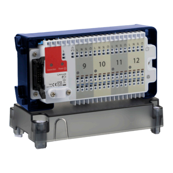
Extension module for KL08NSB 24V wiring centre
Model: KL04NSB 24V
L1
L1 L2
L1 L2
L1 L2
User manual
4V
DISTRIBUTOR of SALUS CONTROLS:
Importer:
QL CONTROLS Sp. z o.o., Sp. k.
SALUS Controls Plc
Rolna 4,
Units 8-10 Northfield Business Park
43-262 Kobielice,
Forge Way, Parkgate, Rotherham
Poland
S60 1SD, United Kingdom
www.salus-controls.eu
SALUS Controls is part of Computime Group Limited.
In line with the policy of product development, SALUS Controls plc reserves the right to change the
specifications, designs and materials used in production, indicated in this manual, without prior notice.
Introduction
The KL04NSB24V module is an extension to the KL08NSB24V wiring centre with another 4 heating zones.
It works only in combination with the KL08NSB24V wiring centre and increases the functionality of the
combined set to 12 individually controlled heating zones.
Product compliance
Directives: Electromagnetic Compatibility Directive EMC 2014/30 / EU, Low Voltage Directive LVD 2014/35
/ EU and RoHS Directive 2011/65 / EU.
Full information is available at www.saluslegal.com
Safety information
Use in accordance with the regulations in force in a given country and in the EU. The device should be
used in accordance with its intended purpose, avoiding moisture. The product is for indoor use only.
Installation must be carried out by a qualified person, in accordance with the rules in force in the country
and in the EU.
Before performing any activities related to the power supply (connecting cables, device installation, etc.),
make sure that the wiring centre and the module are not connected to the mains! Installation should
be performed by a person with appropriate electrical qualifications. Incorrect wiring may damage the
devices. The module cannot be used in conditions of water vapor condensation, nor can it be exposed
to water.
Technical Information
Power supply
From KL08NSB24V wiring centre
Rating max
3 A
Output
24V AC thermoelectric actuator
Dimension [mm]
163 x 85 x 67
Wiring centre description
1. Serial connector
2. Connection LED diode
3. Power LED diode
L1 L2
L1 L2
L1 L2
L1 L2
L1 L2
1. Serial connector
The Serial connector is used to connect the KL08NSB 24V with the KL04NSB 24V extension module to add
functionality and support up to 12 zones
L1
L1 L2
L1 L2
L1 L2
L1 L2
L1 L2
L1 L2
KL08NSB
24V
2. Connection LED diode
Reset
Correct connection of the KL08NSB24V wiring centre with the KL04NSB24V module is
0
indicated by a glowing
O
KL04NSB
3. Power LED diode
Reset
0
When the module is connected to the power supply, the
O
1
2
3
4
KL04NSB
4. NSB function terminals
The NSB function is activated in the Salus Expert series daily thermostats, eg. HTR, by means of an
external clock or weekly thermostats of the said series. Daily thermostats, receiving the NSB signal, lower
the set temperature (by switching to the economy mode). All thermostats must be connected with a
1
2
3
4
4-wire cable (min. 4 x 0.75 mm2, max. 4 x 1.5 mm2).
1
Reset
0
1
2
3
4
L1
L2
L1 L2
L1
L1 L2
L1 L2
Reset
0
KL04NSB
24V
1
2
3
4
red
diode (Connection).
red
LED (Power) lights up.
4. NSB function terminals
5. Actuators connection
6. Thermostats connection
4
2
3
6
L1
L1
L2
L1 L2
L1 L2
KL04NSB
24V
group iii
• OPTION 1
jumpers
One Master thermostat common for Group 1, Group 2 and Group 3 thermostats (one
weekly thermostat, eg. VS30, other daily thermostats, eg. VS35).
L 1-4
5-8 9-12
L1 L2
L1 L2
• OPTION 2
no jumpers
Three Master Thermostats. One for Group 1, one for Group 2 and one for Group 3
thermostats (three weekly thermostats, eg. VS30, other daily thermostats, eg. VS35).
L 1-4
5-8 9-12
• OPTION 3
jumpers
One external clock, common for Group 1, Group 2 and Group 3 thermostats (one
external clock, daily thermostats, eg. VS35).
L 1-4
5-8 9-12
• OPTION 4
Three external clocks. One for Group 1, one for Group 2 and one for Group 3 thermostats
(three external clocks, daily thermostats, eg. VS35).
Note: The 1-4 terminals and 5-8 are on the KL08NSB24V wiring centre,
L 1-4 5-8 9-12
and the 9-12 terminals are on the KL04NSB24V extension module.
L1 L2
5
Advertisement

Related Manuals for Salus KL04NSB 24V


Summary of Contents for Salus KL04NSB 24V
- Page 1 The KL04NSB24V module is an extension to the KL08NSB24V wiring centre with another 4 heating zones. The Serial connector is used to connect the KL08NSB 24V with the KL04NSB 24V extension module to add One Master thermostat common for Group 1, Group 2 and Group 3 thermostats (one...
- Page 2 DIN rail, open the hooks on the back of the housing. Connect the serial cable to RT10 24V VS30 the KL08NSB 24V and KL04NSB 24V connector. L1 L2 NO NC 12 mm Make sure that all the wires are...