Table of Contents
Advertisement
Quick Links
Advertisement
Table of Contents

Related Manuals for Siemens SIRIUS 3SB2


Summary of Contents for Siemens SIRIUS 3SB2
- Page 1 3SB2 pushbuttons and indicator lights Introduction Safety instructions Description Industrial controls Mounting SIRIUS 3SB2 pushbuttons and indicator Connecting lights Technical specifications Configuration Manual Dimension drawings Circuit diagrams 05/2020 A5E43900767002A/RS-AA/001...
- Page 2 Note the following: WARNING Siemens products may only be used for the applications described in the catalog and in the relevant technical documentation. If products and components from other manufacturers are used, these must be recommended or approved by Siemens. Proper transport, storage, installation, assembly, commissioning, operation and maintenance are required to ensure that the products operate safely and without any problems.
-
Page 3: Table Of Contents
Purpose of this documentation ....................5 Target group ..........................5 Required knowledge ......................... 5 Siemens Industry Online Support ..................... 6 Siemens Industry Online Support app ..................8 Support Request ........................8 Safety instructions ........................... 9 Important notes ......................... 9 Before commencing work: Isolating the equipment from the supply system and ensuring that it cannot be reconnected.................. - Page 4 Conductor cross-sections ...................... 23 Connections ........................... 23 Solder pin connection ......................23 Technical specifications ........................25 Technical data in Siemens Industry Online Support .............. 25 Overview tables........................25 Technical specifications ......................26 Dimension drawings ..........................29 Actuating elements ........................ 29 Contact blocks with flat connector ..................
-
Page 5: Introduction
Introduction Purpose of this documentation This manual describes the possible uses of SIRIUS command and signaling devices. In order to provide users with the information they need to operate the system safely, this manual provides a general explanation of operating principles, selection and installation of pushbuttons and indicator lights. -
Page 6: Siemens Industry Online Support
Introduction 1.4 Siemens Industry Online Support Siemens Industry Online Support Information and service At Siemens Industry Online Support you can obtain up-to-date information from our global support database: ● Product support ● Application examples ● Forum ● mySupport Link: Siemens Industry Online Support (https://support.industry.siemens.com/cs/de/en) - Page 7 Configure your individual documentation from different manuals. ● CAx data Easy access to CAx data, e.g. 3D models, 2D dimension drawings, EPLAN macros, device circuit diagrams ● My IBase registrations Register your Siemens products, systems and software. 3SB2 pushbuttons and indicator lights Configuration Manual, 05/2020, A5E43900767002A/RS-AA/001...
-
Page 8: Siemens Industry Online Support App
Siemens Industry Online Support app Siemens Industry Online Support app The Siemens Industry Online Support app provides you access to all the device-specific information available on the Siemens Industry Online Support portal for a particular article number, such as operating instructions, manuals, data sheets, FAQs etc. -
Page 9: Safety Instructions
Siemens. Nor can Siemens assume liability for recommendations that appear or are implied in the following description. No new guarantee, warranty, or liability claims beyond the scope of the Siemens general terms of supply are to be derived or inferred from the following description. -
Page 10: Recycling And Disposal
Siemens’ products and solutions undergo continuous development to make them more secure. Siemens strongly recommends that product updates are applied as soon as they are available and that the latest product versions are used. Use of product versions that are no longer supported, and failure to apply the latest updates may increase customer’s exposure... -
Page 11: Description
Description Application areas The 3SB2 pushbuttons and indicator lights are provided for front plate mounting and rear connection with flat connectors. Contact blocks and lampholders with solder pins are also available for use on PCBs. The 3SB2 series with a nominal diameter of 16 mm is ideal for use in confined operating areas. -
Page 12: Overview Of 3Sb2 Pushbuttons
Description 3.2 Overview of 3SB2 pushbuttons Overview of 3SB2 pushbuttons Pushbuttons and illuminated pushbuttons, round plastic version, 16 mm in diameter Pushbutton with flat button Illuminated pushbutton Pushbutton with raised Illuminated pushbutton with flat button button with raised button Article No. Article No. -
Page 13: Overview Of 3Sb2 Indicator Lights
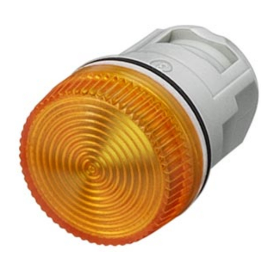
Description 3.3 Overview of 3SB2 indicator lights Overview of 3SB2 indicator lights Indicator light, round plastic version, 16 mm in diameter With concentric rings With smooth lens, for labeling with insert caps Article No. Article No. Black — — 3SB2001-6BC06 3SB2001-6CC06 Yellow 3SB2001-6BD06... -
Page 14: Overview Of 3Sb2 Key-Operated Switches, Selector Switches And Emergency Stop Mushroom Pushbuttons
Description 3.4 Overview of 3SB2 key-operated switches, selector switches and EMERGENCY STOP mushroom pushbuttons Overview of 3SB2 key-operated switches, selector switches and EMERGENCY STOP mushroom pushbuttons Key-operated switch Selector switch with holder EMERGENCY STOP mushroom pushbutton Diameter 16 mm, CES Black, not illuminated Illuminated Diameter 16 mm... -
Page 15: Mounting
Mounting Version with flat connector Button, flat Illuminated button, flat Screw lens for indicator light Insert label, for inscription Insert cap, for inscription Collar with extruded front ring Collar for indicator light Frame for square design Wedge base lamp W2 x 4.6 d Holder Lamp socket with holder Contact blocks (1 NO or 1 NC) for snapping onto holder or lamp socket... -
Page 16: Module Mounting On A Printed Circuit Board
Mounting 4.2 Module mounting on a printed circuit board Module mounting on a printed circuit board WARNING Risk of serious injury. No liability shall be accepted for any damage or injuries sustained as a result of improper use or incorrect dismantling of the equipment (i.e. opening of components other than those specifically designed to be opened by the user). - Page 17 Mounting 4.2 Module mounting on a printed circuit board Minimum distances between actuators installed on front plate Round version 19 mm 19 mm Square version without labeling plate 21 mm 21 mm Round and square version with labeling plate 21 mm 32 mm For 2 selector switches with 3 switch positions, latching, side by side 21 mm...
-
Page 18: Module Mounting On A Printed Circuit Board
Mounting 4.3 Module mounting on a printed circuit board Module mounting on a printed circuit board Distances between spacing bolts NOTICE Risk of material damage. Make sure that the printed circuit board is supported by spacing bolts in such a way that it cannot sag or bend more than 0.1 mm when the command devices are actuated. -
Page 19: Mounting The Contact Block On A Front Plate
Mounting 4.4 Mounting the contact block on a front plate Mounting the contact block on a front plate Mounting the entire module ① ③ 1. Insert the actuator from the front through the opening and latch it with the holder (contact block holder). -
Page 20: Dismantling The Contact Block
Mounting 4.5 Dismantling the contact block Dismantling the contact block Dismantling the complete module 1. Unsolder the printed circuit board. 2. Release the snap-in hooks of the contact blocks. ② ③ 3. Remove the clamping screws from the holder ⑦ ⑧... -
Page 21: Mounting A Button
Mounting 4.7 Mounting a button Mounting a button 1. Place the button 3SB2910-0.. on the holder. 2. Screw the button into position using the assembly tool for buttons and lenses 3SB2908- 2AC. 3. Dismantle by carrying out the above steps in reverse order. Mounting with EMERGENCY STOP EMERGENCY STOP mushroom pushbuttons The 3SB2000-1AC01 and 3SB2203-1AC01 EMERGENCY-STOP mushroom pushbuttons... -
Page 22: Variants
Mounting 4.9 Variants Variants Two device versions can be mounted: ● Round: The 3SB2 pushbuttons and indicator lights are assembled with the modules – actuator, holder, contact block and lampholder. Depending on the specific application, various versions can be assembled. Complete units are offered for the most commonly used applications. -
Page 23: Connecting
Connecting Grounding Note Grounding is required for voltages higher than protective extra low voltage. With voltages of > 50 V AC or 120 V DC, the device has to be grounded. Active parts must not be grounded or connected to higher voltage parts. Conductor cross-sections 3SB2 2 x (0.5 ... - Page 24 Connecting 5.4 Solder pin connection 3SB2 pushbuttons and indicator lights Configuration Manual, 05/2020, A5E43900767002A/RS-AA/001...
-
Page 25: Technical Specifications
Technical data in Siemens Industry Online Support Technical data sheet You can also find the technical data of the product at Siemens Industry Online Support (https://support.industry.siemens.com/cs/ww/en/ps/16444/td). 1. Enter the full article number of the desired device in the "Product" field, and confirm with the Enter key. -
Page 26: Technical Specifications
Technical specifications 6.3 Technical specifications Technical specifications Type 3SB2 Contact blocks and lampholders Standards IEC 60947-5-1, EN 60947-5-1 IEC 60947-5-5, EN 60947-5-5 Rated insulation voltage U Conventional thermal current I Rated operational currents I at rated operational voltage U Alternating current AC-12 At U = 230 V •... - Page 27 Technical specifications 6.3 Technical specifications Type 3SB2 Mechanical endurance 10 x 10 operating cycles Pushbutton 10 x 10 operating cycles Actuators, rotary or latching 3 x 10 operating cycles Illuminated pushbuttons 3 x 10 operating cycles Degree of protection according to IEC 60529 (VDE 0470 Part 1) IP00 Connection of contact blocks and lampholders behind the front plate •...
- Page 28 Technical specifications 6.3 Technical specifications 3SB2 pushbuttons and indicator lights Configuration Manual, 05/2020, A5E43900767002A/RS-AA/001...
-
Page 29: Dimension Drawings
Dimension drawings Actuating elements Note All dimensions specified in mm. Pushbutton or illuminated pushbutton With flat button Figure 7-1 3SB20..-0A... / 3SB22..-0A... Pushbutton or illuminated pushbutton With raised button Figure 7-2 3SB20..-0L... / 3SB22..-0L... Indicator light Figure 7-3 3SB2001-6..06 3SB2 pushbuttons and indicator lights Configuration Manual, 05/2020, A5E43900767002A/RS-AA/001... - Page 30 Dimension drawings 7.1 Actuating elements Selector switch Figure 7-4 3SB2.0.-2..01 CES key-operated switch Figure 7-5 3SB2.0.-4..01 EMERGENCY STOP mushroom pushbutton Acc. to ISO 13850 Figure 7-6 3SB2.0.-1AC01 3SB2 pushbuttons and indicator lights Configuration Manual, 05/2020, A5E43900767002A/RS-AA/001...
-
Page 31: Contact Blocks With Flat Connector
Dimension drawings 7.2 Contact blocks with flat connector Contact blocks with flat connector Pushbutton and contact block With holder for front plate mounting Contact blocks with solder pins for mounting on printed circuit boards Illuminated pushbutton switch With contact block and lampholder with solder pins Length a of spacing bolts: a = 44 minus thickness of front plate. - Page 32 Dimension drawings 7.3 Contact blocks with solder pins for mounting on printed circuit boards 3SB2 pushbuttons and indicator lights Configuration Manual, 05/2020, A5E43900767002A/RS-AA/001...
-
Page 33: Circuit Diagrams
Circuit diagrams Operating travel diagrams 3SB2 pushbuttons and indicator lights Configuration Manual, 05/2020, A5E43900767002A/RS-AA/001... - Page 34 Circuit diagrams 8.1 Operating travel diagrams 3SB2 pushbuttons and indicator lights Configuration Manual, 05/2020, A5E43900767002A/RS-AA/001...
-
Page 35: Index
Index Application areas 3SB2 pushbuttons and indicator lights, 11 Key-operated switches, 11 Dismantling Lamp, 22 Documentation Target group, 5 Important notes, 9 Lamp replacement, 22 Mounting Actuating element, 19 Button, 21 on printed circuit board, 16 Screw lens, 20 Overview 3SB2 EMERGENCY STOP mushroom pushbuttons, 14 3SB2 illuminated pushbuttons, 12... - Page 36 Index 3SB2 pushbuttons and indicator lights Configuration Manual, 05/2020, A5E43900767002A/RS-AA/001...