Table of Contents
Advertisement
Quick Links
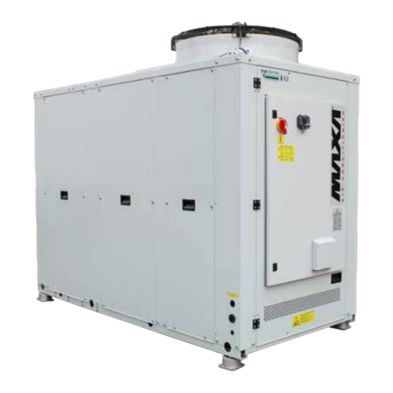
Chiller and Inverter Air/Water heat pumps with axial fan
User-Installer Manual
Models
i-HPV5H 0140
i-HPV5H 0250
i-HPV5H 0260
i-HPV5H 0270
This manual has been created for informative purpose. The company declines any responsibility for the results of any projecting or any installation based on the
explanations and/or on the technical specifications provided in this manual. It is besides forbidden the reproduction under any form of the texts and of the figures
contained in this manual. This manual is a translation from the official italian language version. For reasons of environmental respect the Company will not provide
the hard copy in the original language which could be directly requested or downloaded from the Company website at any time. In case of any dispute, the original
language manual will be the trusted one. Even partial reproduction PROHIBITED © Copyright - Advantix SpA
www.maxa.it
R32
Advertisement
Table of Contents

Related Manuals for Trane MAXA i-HPV5H 0140


Summary of Contents for Trane MAXA i-HPV5H 0140
- Page 1 Chiller and Inverter Air/Water heat pumps with axial fan User-Installer Manual Models i-HPV5H 0140 i-HPV5H 0250 i-HPV5H 0260 i-HPV5H 0270 This manual has been created for informative purpose. The company declines any responsibility for the results of any projecting or any installation based on the explanations and/or on the technical specifications provided in this manual.
- Page 2 i-HPV5 Inverter air/water heat pumps with axial fan 10-2021 AL.B. A.R. Update Hz max/min, KA2 kit 06-2021 AL.B A.R. First emission Date Compiled Approved Note Code Serie MUI01080120001-01 Inverter air/water heat pumps with axial fan...
-
Page 3: Table Of Contents
i-HPV5 Inverter air/water heat pumps with axial fan Contents 1. PURPOSE AND CONTENTS OF THE MANUAL ..............5 1.1 HOW TO KEEP THE MANUAL ..................5 1.2 GRAPHIC SYMBOLS USED IN THE MANUAL ............5 2. NORMATIVE REFERENCES ....................5 3. PERMITTED USE ....................... 5 4. - Page 4 i-HPV5 Inverter air/water heat pumps with axial fan 8. SHUTDOWNS FOR LONG PERIODS ................26 9. MAINTENANCE AND PERIODIC CHECKS ..............27 9.1 GENERALITY ......................28 9.1.1 Cleaning the filled coil treated with the anti-corrosion method ......28 9.2 CLEANING OF EXTERNAL SURFACES ..............29 9.3 EXTRAORDINARY MAINTENANCE ................
-
Page 5: Purpose And Contents Of The Manual
i-HPV5 Inverter air/water heat pumps with axial fan The manual of the units contains all the indications for the optimal use of the machine under safe conditions for the operator. 1. PURPOSE AND CONTENTS OF THE MANUAL This manual provides basic information as to the selection, installation, operation and maintenance of the unit. It is intended for the operators of the appliance and it enables them to use the equipment efficiently, even if they do not have any previous specific knowledge. -
Page 6: General Safety Guidelines
i-HPV5 Inverter air/water heat pumps with axial fan improper and therefore not allowed. The fluid to be used is exclusively water or a mixture of water and glycol in case of low water tem- peratures. It is absolutely NOT allowed to connect the heated water supply from the UNIT directly to the taps of the domestic hot wa- ter circuit. -
Page 7: Personal Protective Equipment
i-HPV5 Inverter air/water heat pumps with axial fan Do not tamper with or replace parts of the unit without the specific consent of the manufacturer. These interventions re- lease the manufacturer from any civil or legal responsibility. Using components, consumables or spare parts that do not correspond to those recommended by the manufacturer and/or listed in this manual may be dangerous for the operators and/or damage the unit. -
Page 8: Safety Signs
i-HPV5 Inverter air/water heat pumps with axial fan Mask and goggles: Respiratory protection (mask) and eye protection (goggles) should be used during cleaning operations. 4.3 SAFETY SIGNS The unit features the following safety signs, wich must be complied with: Generic hazard. Dangerous electric voltage. -
Page 9: Refrigerant Safety Data Sheet
i-HPV5 Inverter air/water heat pumps with axial fan 4.4 REFRIGERANT SAFETY DATA SHEET Name: HAZARDS IDENTIFICATION Main hazards: Asphyxia� on. Specifi c hazards: Quick evapora� on could cause it to freeze. FIRST AID MEASURES General informa� on: Do not administer to people who are unconscious. Immediately remove to fresh air. -
Page 10: Specific R32 Gas Warnings
i-HPV5 Inverter air/water heat pumps with axial fan 4.5 SPECIFIC R32 GAS WARNINGS The R32 refrigerant gas: • is odourless; • is flammable, but only if there are naked flame; • it may cause an explosion, but only if a given concentration in air is reached. It is a good practice to follow these guidelines: •... -
Page 11: Transport And Storage Limit Temperature
i-HPV5 Inverter air/water heat pumps with axial fan CAUTION: The unit must be installed so as to allow free movement for repair and maintenance operations. The warranty does not cover costs for platforms or other lifting equipment needed for any interventions. CAUTION: The unit must be installed so as to allow free movement for repair and maintenance operations. -
Page 12: Positioning And Minimum Technical Clearances
i-HPV5 Inverter air/water heat pumps with axial fan Lifting through forklift truck Lifting with lifting tubes and ropes 5.4 POSITIONING AND MINIMUM TECHNICAL CLEARANCES All models of the range are designed and constructed for outdoor installations. It is advisable to create an adequately sized support base for the unit. The units transmit a small amount of vibrations to the ground: it is none- theless advisable to apply vibration dampers between the base frame and support surface. - Page 13 i-HPV5 Inverter air/water heat pumps with axial fan Model i-HPV5H 0140 1200 1000 1000 1500 i-HPV5H 0250 / 1200 1000 1500 1500 0260 / 0270 For strong wind installation place refer to the classification of the area according to the Beaufort table. If the value is > 7 (strong wind, average wind speed = 13,9-17,1 m/s) it is strictly necessary to keep the fan always powered, thus preventing involuntary rotation of the same.
-
Page 14: Dimensions
i-HPV5 Inverter air/water heat pumps with axial fan 5.5 DIMENSIONS 5.5.1 Standard version 212,5 DS / OUT (1" G) DS / IN (1" G) 1754 1110 1850 Dimensions A - Lenght 1850 B - Depht 1110 C - Height 1920 C - Heigh SSL/C/C(S) version 1980 IN / OUT inch... -
Page 15: Centre Of Gravity And Dampers Location
i-HPV5 Inverter air/water heat pumps with axial fan 5.6 CENTRE OF GRAVITY AND DAMPERS LOCATION In the following tables, we report the position of the barycentre of each machine, with reference to the dimensions shown in the image. A dis- tinction is made between standard machine version, with hydronic kit (single/double pump) and if the tank is also installed. Models Version A [mm]... -
Page 16: Accessing The Inner Parts
i-HPV5 Inverter air/water heat pumps with axial fan The ideal installation positions of the dampers for each type of machine are shown in the below images. Models Version A [mm] B [mm] C [mm] D [mm] Standard 1410 i-HPV5H 0140 / 0250 0260 / 0270 Hydronic kit with tank 2180... -
Page 17: Access To The Inside Of The Unit On The Hydronic Kit Side
i-HPV5 Inverter air/water heat pumps with axial fan 5.7.2 Access to the inside of the unit on the hydronic kit side In the event of maintenance and/or inspection of the hydronic part and part of the refrigeration circuit, it is necessary to access the inside of the unit from the rear side, near the hydraulic connections. -
Page 18: Features Of The Circuit Water
i-HPV5 Inverter air/water heat pumps with axial fan The heating system and the safety valves must comply with the requirements of standard EN 12828. The unit is pre-tensioned on the side cover plate in order to provide a suitable passage for the discharge of the safety valve (the installation of which is the responsibility of the user). - Page 19 i-HPV5 Inverter air/water heat pumps with axial fan STANDARD HYDRONIC CIRCUIT WITH OPTIONAL ACCESSORIES EV/CO HKA1 W-OUT W-IN HKA2 HYDRONIC CIRCUIT SINGLE PUMP VERSION (WITH OPTIONAL TANK) W-OUT EV/CO HKA1 W-OUT W-IN HKA3 HKA2...
-
Page 20: Drainage System
i-HPV5 Inverter air/water heat pumps with axial fan HYDRONIC CIRCUIT DOUBLE PUMP VERSION (WITH OPTIONAL TANK) W-OUT EV/CO HKA1 W-OUT W-IN HKA2 HKA3 HKA2 ATTENTION: It is recommended to connect the safety valve vent in an appropriate conveyor / discharge. Otherwise the discharged water could stagnate around the unit and become a source of danger due to slipping / falling. -
Page 21: Service Sleeves
i-HPV5 Inverter air/water heat pumps with axial fan It is advisable to use an external tap to fill the system, which is the responsibility of the installer. There is always a service tap in the unit to be used if it is necessary to top up/ discharge the amount of water in the system or adjust the percentage of glycol. -
Page 22: Access To Electric Panel
i-HPV5 Inverter air/water heat pumps with axial fan CAUTION: Any devices placed nearby can cause / suffer electromagnetic disturbances to / from the unit. Be aware of this risk at the installation site. It is recommended to electrically power the unit with an adequate line and protections and use an independent cable duct. -
Page 23: User Terminal Block
i-HPV5 Inverter air/water heat pumps with axial fan 5.9.3 User terminal block The connection terminal block is located under the machine cover. For access, see the instructions. The terminal block must be connected re- specting the notes below. The connections shown below are standard. Other connections are given in the MCO manual of the on-machine control (see "USER AND IN- STALLER CONFIGURATION TABLES"), according to the configurations adopted. -
Page 24: Control Logics
i-HPV5 Inverter air/water heat pumps with axial fan Control terminal block Power terminal block Standard Standard Expansion (GI) Expansion (GI) 10.1 11.1 12.1 13.1 14.1 15.1 16.1 10.1 10.2 11.2 12.2 13.2 14.2 15.2 16.2 GI D 10.2 10.2 11.2 12.2 13.2 14.2... -
Page 25: Functional Diagrams
i-HPV5 Inverter air/water heat pumps with axial fan 5.10 FUNCTIONAL DIAGRAMS Below are the conceptual diagrams of the chiller and heat pump version and the legend for all diagrams. LEGEND COMPRESSOR SUCTION LINE CONDENSER MOISTURE LIQUID INIDACTOR EVAPORATOR PEH TC HIGH-PRESSURE TRANSDUCER ELECTRONIC EXPANSION VALVE PED TR LOW-PRESSURE TRANSDUCER... -
Page 26: Start Up
i-HPV5 Inverter air/water heat pumps with axial fan 6. START UP Before start-up: 1. Check that the diagrams and manuals of the installed machine are available. 2. Check that the wiring and plumbing diagrams of the plant the machine is connected to are available. 3. Check that the shut-off valves of the water circuits are open. -
Page 27: Maintenance And Periodic Checks
i-HPV5 Inverter air/water heat pumps with axial fan If the temperature drops below zero there is serious danger of frost: provide a mixture of water and glycol in the system, otherwise drain the water system and the circuits of the heat pump. CAUTION: even the transient operation, with water temperatures below +5°C is not guaranteed on the basis of the limits es- tablished. -
Page 28: Generality
i-HPV5 Inverter air/water heat pumps with axial fan OPERATION M / R month months months months Filling the water circuit. Presence of bubbles in the water circuit. Check the proper working of the safety and control devices. Check that there are no oil leaks from the compressor. Check if there is a possible water leakage from the water circuit. -
Page 29: Cleaning Of External Surfaces
i-HPV5 Inverter air/water heat pumps with axial fan CAUTION: Do not clean the coil using high-pressure cleaners so as not to apply excessive pressure which could cause irrepa- rable damage. Damage caused by cleaning with unsuitable chemical substances or excessively high water pressure will not be recognised under warranty. -
Page 30: Residual Risk
i-HPV5 Inverter air/water heat pumps with axial fan An incorrect decommissioning of the appliance may create serious environmental damage and endanger people’s safety. Therefore, it is recommended that the unit be disposed only by authorised persons with technical training who have attend- ed training courses acknowledged by the competent authorities. - Page 31 i-HPV5 Inverter air/water heat pumps with axial fan User / Activity Operator User Danger Indication / Istruction Residual risk The correct maintenance Mechanical: cut / abrasion procedures are indicated in the caused by the presence of edges Failure to comply with the proce- user-installer manual under chap- on the external casing of the ma- dures and / or failure to use PPE...
- Page 32 i-HPV5 Inverter air/water heat pumps with axial fan User / Activity Operator User Danger Indication / Istruction Residual risk Caused by radiation: electro- magnetic radiation that the unit No one generates during operation The use of personal protective equipment is recommended in Generated by materials / sub- the user-installer manual under Failure to comply with the...
- Page 33 i-HPV5 Inverter air/water heat pumps with axial fan User / Activity Operator User Danger Indication / Istruction Residual risk In the user-installer manual un- der chapter 9 it is recommended to carry out maintenance only in weather conditions suitable for the operations envisaged.
-
Page 34: Technical Data
i-HPV5 Inverter air/water heat pumps with axial fan TECHNICAL DATA 12.1 TECHNICAL SHEET HEAT PUMP Performance referring to the following conditions,according to standard 14511:2018: (1) Cooling: outdoor air temperature 35°C; in/out water temperature 12/7°C. (2) Cooling: outdoor air temperature 35°C; in/out water temperature. 23/18°C. (3) Heating: outdoor air temperature 7°C b.s. - Page 35 i-HPV5 Inverter air/water heat pumps with axial fan i-HPV5H TECHNICAL CHARACTERISTICS Unit 0140 0250 0260 0270 Cooling capacity (1) min/nom/max 14/29,7/33,3* 20,4/36,2/39,1* 25,4/48/53,1* 27,6/52,7/58,7* Power input (1) 9,62 11,8 15,6 17,8 E.E.R. (1) 3,09 3,07 3,08 2,96 Cooling capacity (2) min/nom/max 19,6/37,2/41,9* 31,3/55,1/62,7* 37,2/65,1/71,6* 38,2/65,6/73,6* Cooling Power input (2)
- Page 36 i-HPV5 Inverter air/water heat pumps with axial fan i-HPV5H -PS/PSI/PD TECHNICAL CHARACERISTICS Unit 0140 0250 0260 0270 Cooling capacity (1) min/nom/max 14/29,6/33,1* 20,1/36,3/41,2* 25,3/48/53,1* 27,1/53,2/58,2* Power input (1) 9,54 11,7 15,5 17,7 E.E.R. (1) 3,10 3,10 3,10 3,01 Cooling capacity (2) min/nom/max 18,8/37,3/42,4* 31,2/55,3/62,3* 37,2/65,3/71,8* 38,5/66/73,8* Cooling...
- Page 37 i-HPV5 Inverter air/water heat pumps with axial fan i-HPV5H -PSEC TECHNICAL CHARACTERISTICS Unit 0140 0250 0260 0270 Cooling capacity (1) min/nom/max 13,5/29,4/33,1* 19,7/35,7/40,4* 25/47,4/52,7* 26,8/53,1/57,7* Power input (1) 10,20 12,2 15,8 18,1 E.E.R. (1) 2,88 2,93 3,00 2,93 Cooling capacity (2) min/nom/max 19,2/37,3/41,2* 30,8/54,2/63,4* 36,9/64,8/72,2* 38,1/66,5/74,3* Cooling Power input (2)
-
Page 38: Unit And Auxiliary Electrical Data
i-HPV5 Inverter air/water heat pumps with axial fan 12.2 UNIT AND AUXILIARY ELECTRICAL DATA Unit power supply V/~/Hz 400/3PH+PE/50 On board controller circuit V/~/Hz 12/1/50 Remote controller circuit V/~/Hz 12/1/50 Fan power supply V/~/Hz 400/3PH+PE/50 NOTE: The electrical data are subject to change due to updates. It is therefore always necessary to refer to the technical specifications label applied on the right side panel of the unit. - Page 39 i-HPV5 Inverter air/water heat pumps with axial fan Heat pump mode for domestic hot water 0140 / 0270 Room temperature with water at maximum +50 °C Minimum -12 °C Maximum +39 °C Outlet water temperature Minimum +25 °C Maximum +58 °C Heat pump mode for domestic hot water 0250 / 0260 Room temperature with water at maximum +58 °C Minimum -9 °C...
- Page 40 i-HPV5 Inverter air/water heat pumps with axial fan CHILLER MODE Pun� estremi envelope UNITÀ - Raffrescamento Standard -14 -10 [°C] DOMESTIC HOT WATER MODE i-HPV5H 0140 / 0270 Pun� estremi envelope UNITÀ - ACS [°C] DOMESTIC HOT WATER MODE i-HPV5H 0250 / 0260 Pun�...
-
Page 41: User Interface - Controller
i-HPV5 Inverter air/water heat pumps with axial fan USER INTERFACE - CONTROLLER The unit includes a display placed underneath a hinged polycarbonate transparent door with a protection rating of IP67. The interface has a part with variable text and a series of icons identifying operation of the unit as shown in the table below. Cooling mode led: led ON if unit is in COOL or COOL+SAN mode. -
Page 42: Menu
i-HPV5 Inverter air/water heat pumps with axial fan The DOWN key is used to move to a lower menu or to decrease the value of a parameter. In standard operation, the display shows the water outlet temperature in tenths of Celsius degrees or the alarm code if at least one is active. If several alarms are triggered, the first one is displayed while the second one will be displayed as soon as the first one is reset. - Page 43 i-HPV5 Inverter air/water heat pumps with axial fan PROBLEM CAUSE SOLUTION Increase in discharge pressure Low inlet pressure Incorrect power supply Check Compressor does not start be- Incorrect wiring cause of protective devices Incorrect working conditions Thermal protection intervention Damaged pressure switch Repalce High outside air temperature High water return temperature...
- Page 44 i-HPV5 Inverter air/water heat pumps with axial fan...
- Page 45 i-HPV5 Inverter air/water heat pumps with axial fan...
- Page 46 i-HPV5 Inverter air/water heat pumps with axial fan...
- Page 47 i-HPV5 Inverter air/water heat pumps with axial fan...
- Page 48 ADVANTIX SpA Via S. Giuseppe Lavoratore 24, 37040 Arcole (VR) Italy Tel. (+39).045.76.36.585 E-mail: info@advantixspa.it www.maxa.it...