Advertisement
Quick Links
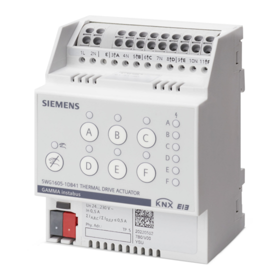
Thermal Drive Actuator N 605D41, 6 x AC 24...230 V
N 605D41
A6V13488290_en--_a
2023-02-07
The thermal drive actuators are used for controlling electro-thermal actuators
for heating or cooling systems.
●
6 semiconductor outputs for noiseless control of AC 24 V or AC 230 V actuators
●
Direct operation for efficient installation with switching status and control value dis-
play via LED.
●
Error LEDs on the device front for indicating a mains voltage failure and overload/
short circuit faults
●
Maintenance-free terminals for connecting and looping through solid, stranded and
fine-stranded conductors.
Functions for configuration with ETS:
●
With priority control of security and override functions
●
Automatic or demand-based or manual valve flushing
●
Extensive, internal room temperature controllers and ventilation controllers (which
can be assigned freely or for each channel)
●
Powerful calculator modules for weighting temperature values or determining the
largest or a weighted control value
●
Interaction with primary systems for heating demand or cooling demand require-
ments and demand-based pump control.
Smart Infrastructure
Advertisement

Related Manuals for Siemens N 605D41


Summary of Contents for Siemens N 605D41
- Page 1 Thermal Drive Actuator N 605D41, 6 x AC 24...230 V N 605D41 The thermal drive actuators are used for controlling electro-thermal actuators for heating or cooling systems. ● 6 semiconductor outputs for noiseless control of AC 24 V or AC 230 V actuators ●...
- Page 2 AC 230 V or AC 24 V actuators per channel or channel group according to their power consumption. When using Siemens STA/STP actuators, up to 6 (AC 230 V) or up to 4 (AC 24 V) actuators can be controlled per channel.
- Page 3 Programming mode Fig. 1: Programming button and programming LED (exemplary illustration) After bus voltage recovery, wait several seconds before pushing the programming (1) but- ton (not before booting is complete). Activate programming mode a) Briefly press the programming button (1) (< 2 seconds). ð...
- Page 4 Controlling the actuator channels The actuator channels are controlled via switching commands On/Off (1-bit); the telegrams are converted directly at the output Continuous positioning commands in percent (1 byte) are converted into a switching control of the thermal actuators via pulse width modulation (PWM) or via limit value evaluation (limit values for opening or closing the valve).
- Page 5 Valve flushing Valve flushing is used to protect against calcification and seizure of valves that are not used for an extended period of time Manual valve flushing Start (for the set duration)/stop via a 1-bit object Automatic valve flushing Cyclically in weeks or demand-oriented if the control value remains below a limit value. Valve flushing is reactivated at a control value of 0%.
- Page 6 Logic operations The thermal drive actuator has 6 independent logic blocks with which different mathematical operations are possible: AND, OR, XOR, TRIGGER, LOCK. The inputs can be linked internally in the device with the status output of the valve control values of a channel or with any KNX communication objects, including external devices.
- Page 7 Diagnostic routine Each channel or a channel group of the thermal drive actuator detects an overload or a short circuit on the valve outputs. Here, a diagnostic routine is executed, which works group by group for the channel outputs A/B/C or D/E/F and takes approx. 60 s. Fig. 4: Display of the diagnostic routine Description ●...
- Page 8 Overload on the channel groups In the event of a total current overflow of a group of channel outputs, the error LEDs of the affected channel group on the front of the device light up continuously (fig. “,” 1). The overload can be reported via the bus. Fig. 6: Error display for overload on the channel groups Description ●...
- Page 9 Schematic design of a thermal drive actuator channel 1 bit 8 bit Control value monitoring Error control value Control value limitation Override 1 – 6 ≥ 1 active PWM calculation Valve flushing Valve flushing Valve flushing status start/stop Direct operation Status control value (1 bit) Status control value (8 bit) Status switching...
- Page 10 Technical design Position and function of the connections and labeling Ɛ Fig. 7: Position and function of the connections and labeling, Thermal Drive Actuator N 605D41, 6 x AC 24...230 V Pos. Element Function 1 Connection pins for KNX bus terminal Connect KNX bus.
- Page 11 Position and function of the operating and display elements Fig. 8: Operating and display elements, Thermal Drive Actuator N 605D41, 6 x AC 24...230 V Pos. Operating or display element Function 1 Programming LED (red), Short push of button (< 2 s): Programming button ●...
- Page 12 Pos. Operating or display element Function 5 Status LED of a channel (red) Indicates the status of the respective channel. Bus operation: ● 2-point controller/2-point operation: – LED ON: Valve is opened under consideration of the valve control direction. – LED OFF: Valve is closed under consideration of the valve control direction.
- Page 13 Type overview Type Description Item number KNX PL-Link N 605D41 Thermal Drive Actuator N 5WG1605-1DB41 605D41, 6 x AC 24...230 Version of the Engineering Tool Software Application Version Engineering Tool Software (ETS) ETS 5 or above Accessories Type Order number...
- Page 14 Documents related the product, such as operating and installation instructions, application program description, product database, additional software and CE declarations can be downloaded from the following website: http://www.siemens.com/gamma-td Frequently asked questions For frequently asked questions about the product and their solutions, see: https://support.industry.siemens.com/cs/products?dtp=Faq&mfn=ps&lc=de-WW...
- Page 15 Notes Security CAUTION National safety regulations Failure to comply with national safety regulations may result in personal injury and property damage. ● Observe national provisions and comply with the appropriate safety regulations. WARNING Risk of death due to electric voltage and electric current! Electrical expertise is required for the installation.
- Page 16 Start-up Connecting thermal actuators to the semiconductor outputs Fig. 9: Thermal Drive Actuator N 605D41, 6 x AC 24...230 V 0.5...2.5 mm² 2.5 mm² Smart Infrastructure A6V13488290_en--_a GAMMA Instabus 2023-02-07...
- Page 17 Connecting KNX Fig. 10: Thermal Drive Actuator N 605D41, 6 x AC 24...230 V 0.6…0.8 mm Testing KNX 24 V DC type. SELV This test can be used to check whether the bus connection cable is connected with the cor- rect polarity and whether device is supplied with bus voltage.
- Page 18 Status display in bus operation (A|B|C|D|E|F Un~24...230 V) Fig. 12: Thermal Drive Actuator N 605D41, 6 x AC 24...230 V For pulse width modulation (PWM), the flashing of the status LED represents the control of the output. The period duration is 5 s fixed.
- Page 19 24 V Number of actuators per channel or group 230 V per channel and group of 3 outputs in relation to Siemens STA/STP types - see Accessories [} 13] Power loss Maximum power loss of the device at rated 2.1 W...
- Page 20 Failure rate (at 40°C) 471 fit Connection example Fig. 14: Thermal Drive Actuator N 605D41, 6 x AC 24...230 V CAUTION A common supply voltage for all channels is applied to terminals L1 and N. Two output channels share a central ground terminal.
- Page 21 Dimensions Fig. 15: Thermal Drive Actuator N 605D41, 6 x AC 24...230 V Compliance information FCC Statement WARNING Installation and usage of equipment not in accordance with instructions manual may result in: Radiation of radio frequency energy Interference to radio communications ●...
- Page 22 2. this device must accept any interference received, including interference that may cause undesired operation FCC Caution: Changes or modifications not expressly approved by Siemens Switzerland Ltd. could void the user’s authority to operate the equipment. United States representative https://new.siemens.com/us/en/products/buildingtechnologies/home.html Industry Canada statement This device complies with ISED’s license-exempt RSSs.